
#4050 - Honda Ridgeline Owner’s Manual Please save Instructions: Important Warranty and Maintenance
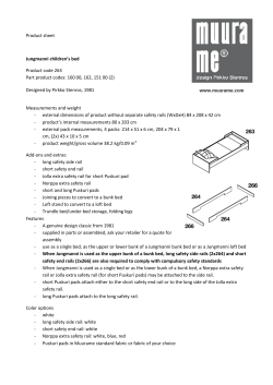
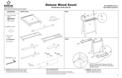
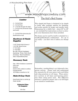
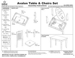
#4050 - Honda Ridgeline Installation Instructions Owner’s Manual Please save Instructions: Important Warranty and Maintenance information enclosed Tailgate End Driver Side Rail (has white lock stop) (2) 10-24 Black flathead Allen Screws Passenger Side Rail (has “inspected by” sticker under rail) (4) 10-32 Screws (stainless) Exploded View Cab End Spiral Canister Assembled View Manufactured in the USA by APPLIED PRODUCTS, INC. An Employee Owned Company 917 South 46th Street Grand Forks, ND 58201 (701) 746-5596 FAX (701) 746-5598 www.rolltopcover.com [email protected] 800-206-4070 Front Cover Scan here to view a brief video on how to install a RETRAX cover. Make sure that you have a QR Code reader application installed on your smartphone. ASSEMBLY AND INSTALLATION INSTRUCTIONS Thank you for your purchase of the RETRAX™ bed cover system. Please read and follow instructions before un-boxing and assembling the bed cover. The RETRAX™ bed cover is shipped in two boxes. Check for shipping damage and keep boxes and packing until installation is complete. If you have any questions or concerns please contact Customer Service@ Voice: 1-800-206-4070 Fax: 1-701-746-5598 or E-mail: [email protected] Remove foam wrapping carefully from parts to prevent scratching. Leave clear plastic protective film on the rolling cover and aluminum canister until installation is complete. Remove protective film before exposing to sunlight. Parts checklist for large box Owner’s packet with keys ----Cover rolled into canister-spiral assembly -- Front cover for canister ---Drain Tube Kit Parts checklist for rail box Driver’s side rail---Passenger side rail---Mounting hardware box Drain tube kit (not shown) (2) Clear tubes w/ drain fittings (2) Foam washers DO NOT USE LOCTITE! USE OF LOCTITE VOIDS WARRANTY Newer models may need rubber spacer at passenger rear mount 4 mm Allen wrench (4) M6 x 40mm (metric) Allen head mounting bolts #40 Torx insert bit (2) ¼” flat washers (2) ¼” lock washers (2) Foam gaskets for front tie-downs (2) Nylon spacers used in rear recessed mount holes (2) Plugs for middle holes. Step #8 (2) 10-24 x 1” Stainless screws with black caps used to mount front cover to front mounting plates Measuring tool NOT NEEDED! (2) Front mounting brackets (2) 10-24 x 3/4" Black Allen head screws Front cover to rail mounting screws (includes1/8” wrench) (4) 10-32 x 7/16” Rail to canister mounting screws Pre-assembly guidelines Two people are recommended for installation and you should allow 1 to 1 ½ hours to complete. Floor space about the size of pickup box is needed for assembly of the bed cover and rails. (2) 1/2" drain tubes connect to the bottom of canister and can exit out the floor or front of the pickup bed. The front floor of the Honda Ridgeline has two plugs covering the bed mounting bolts. Drill a loose 1/2” or a 9/16” hole through these plugs for the drain tubes. See Step 15 (Water will drain around those bolts.) ASSEMBLY AND INSTALLATION INSTRUCTIONS STEP 1 Remove the shipping bracket and yellow wire. Completely remove white shipping tubes. Shipping tube Shipping bracket Remove these items only! The shipping brackets can be disassembled simply by removal of the 10-32 screws fastened to each side of the canister (Remove these items only). The tailgate can then be lifted away from the canister allowing for the removal of the shipping bracket by sliding the T-channel out from the wire ties. The wire ties can then be removed from the bearings without the need for cutting the wire. Pull white shipping tubes completely out of the canister. DO NOT ALLOW THE COVER TO ROLL INTO THE SPIRAL BECAUSE THE BOTTOM OF THE LOCK CAN DAMAGE THE COVER! Driver side view of assembly The rails will be attached to the cover assembly next. The front (cab) ends of the rails have the RETRAX decal attached. The passenger rail is the first to be installed, it has an “inspected by” decal under the front. The driver’s rail has a white nylon lock stop attached to the bracket at the rear (tailgate) end of the rail. STEP 2 Install the passenger rail to the spiral. Passenger rail has “inspected by” sticker under the front of the rail Front attachment hole Bearings enter channel of rail here. Rear attachment hole Start sliding the cover and bearings into the channel of the rail. View from drivers side View from passenger side ASSEMBLY AND INSTALLATION INSTRUCTIONS STEP 2 continued. Slide the rail over the cover until the two threaded holes in the rail are lined up behind the two holes in the spiral. Attach using two of the 10-32 by 7/16" screws. Tighten using a manual #2 Phillips screwdriver. DO NOT USE LOCTITE! USE OF LOCTITE VOIDS WARRANTY STEP 3 Install the drivers rail. Lift up the lock cover and open lock by pressing release button. Pull the cover out of the canister 6”-8” (See PowertraxPRO Installation Supplement on how to move an electric cover). Caution: Be careful- the locking pin is sharp. DO NOT allow cover to roll back into canister until rail is installed. Repeat to install the driver's rail. SIDE VIEW OF FRONT COVER STEP 4 Install the front cover. The front cover is attached below the rails. Hold the front cover level and push both ends in evenly to help slide it into place. When the holes are lined up, start threading the (2) 10-24 x 3/4” Allen head screws. Tighten the 2 screws securely using the 1/8” Allen wrench. (included) A latch is found on a Manual Cover Only. See PowertraxPRO Installation Supplement on how to move electric cover. This end towards tailgate Weather-strip towards cab ASSEMBLY AND INSTALLATION INSTRUCTIONS STEP 5 Attach front seal to rail. After the front cover is installed, remove the adhesive backing paper from under the front of both rails. (Fig. 5a) Push the front seal firmly into place over the adhesive keeping the seal even. (Fig. 5b) Drivers’ front corner Fig. 5a Bottom view passenger side Fig. 5b Bottom view of rail and front cover with front seal installed Drivers’ rear corner STEP 7 Remove factory screws and spacers from both rear posts using #40 Torx bit. Drivers’ rear corner is shown. STEP 6 Remove the factory bolts from both corners of the front wall of the bed. Use #40 Torx bit. (included) Passenger front corner STEP 8 Remove the adhesive backing paper from the foam fillers for the tiedowns. Push into place over the tie-down bolts. Repeat on drivers side. Drivers’ front corner STEP 9 Install front mount brackets as shown. Slide lock washer onto M6 x 40mm bolt, push bolt through hole in mount bracket and start threading into front holes in the bed. Hold mount bracket level and tighten using the 4 mm Allen wrench. (included) Repeat on passenger side. STEP 10 Insert black plastic plugs into middle holes. Push the 2 supplied plugs into the 2 middle factory holes on both sides of the bed. ASSEMBLY AND INSTALLATION INSTRUCTIONS STEP 11 Lift bed cover into place Using two people lift the bed cover at the front and 2 ft back and position into bed above the RETRAX front mount brackets. The bed cover goes below the factory tie-downs. Slide the cover against the front wall. Fig. 11a STEP 11b The weather-strip on the front cover may need to be repositioned. Fig. 11b STEP 12 The holes in the front cover should line up over the threaded holes in the front mount brackets. If needed, lift up slightly on the canister and push the bed cover firmly against the front wall of the bed. Start the (2) 10/24 x 1” front mounting screws with black caps into the brackets but do not tighten yet. Fig. 12 Drivers’ front corner Fig. 11a Lift cover into place over front mount brackets. Fig. 11b Position front covers weather-strip. Passenger front corner Passenger front corner Fig. 12 Start threading the 2 front mounting screws w/black caps through the front cover into the front mount brackets. Do not tighten yet. When all 4 mounting screws are started then tighten front screws using a #2 Phillips screwdriver. Fasten screw cover when finished. ASSEMBLY AND INSTALLATION INSTRUCTIONS Step 13 Start rear mounting screws Slide a flat washer onto the (2) M6 x 40mm (metric) rear mount bolts, insert bolts through holes in rear rail brackets, then insert nylon spacer and start threading into factory holes at rear. Use 4mm Allen wrench. See Step 13a and 13b for passenger rear mount. Tighten all 4 mounting screws securely after all 4 screws have been started. Drivers’ rear mount Step 13a Select proper mounting hole location on passenger rear mount plate. The hole used depends on if the rubber spacer is needed (see below). Most 2008 and older beds use the upper holes without the spacer. During the 2008 model year the passenger side of the Honda tailgate was raised slightly. The late 2008 and newer models use the lower hole and the rubber spacer. This is needed for clearance over the tailgate. Peel off adhesive strip from rubber spacer and attach spacer underneath mount bracket as shown. Passenger rear mount holes Passenger rear mount Step 13a The rubber spacer provided can be added underneath passenger rear mount bracket for proper clearance over factory tailgate protector. ASSEMBLY AND INSTALLATION INSTRUCTIONS STEP 14 Drain Tube Assembly Remove plastic film from the canister. Place the rubber washers over the drain tube fittings. Push the assembled tubes into the 2 holes on the bottom of the canister. The fitting should lock into place; test by pulling down on the fitting, it should not pull out of canister. Rubber washer Drain tube fitting Drain tube STEP 15 Install drain tubes and cut to fit. You can pass the tubes through the 2 factory plastic bed bolt covers. Fig.15a Remove the covers and drill a loose ½” hole or a 9/16’ hole for the tubes. Offset the holes as shown. Fig.15b Water will drain around the factory bolts. Optional Rail Weather Strip Adjustment The inside walls of the Ridgeline bed have a slight bow outward from front to back. This can cause a slight gap (Fig. a) between the rail weather strip and the side wall of the bed. The rail weather strip can be moved towards the bed wall if needed. Push (slide) the weather strip firmly against the wall to close the gap. (Fig. b) Fig. 15a Drivers’ front corner – drain tube installed through plastic bed bolt covers. Rail Fig. 15b Plastic bed bolt covers (Drilled) Rail Wall Rearview passenger side rail Fig. a Wall Rearview passenger side rail Fig. b Please call RETRAX Tech help at 800-206-4070 with any questions or comments. We appreciate your business and any input you may have. Thank you. RetraxPRO MAINTENANCE AND USE INSTRUCTIONS USE The Retrax cover has superior quality, rail weather-strip seals. These seals help minimize water intrusion into the pickup bed. The initial break-in period for the rail weather-strip is about 48 hours in the fully closed position. Your cover may be slightly harder to open and close during the break-in period. 1 Opening and Using the Cover Using your RetraxPRO cover is as simple as opening the lock cover and pressing the button at the center of the latch to pop open the handle (1). If properly installed, the cover should be able to roll open and closed easily with one hand (2). During the break-in period more effort may be needed, but you still should be able to roll the cover open and closed with one hand. 2 Closing and Locking the Cover To latch your RetraxPRO cover anywhere along the rail, push down firmly on the end of the lock handle using both thumbs (3). It takes this amount of force because it is a friction lock in any open position. The RetraxPRO cover is easier to latch in the fully closed position due to a recess in the rail. Securing Loose Cargo 3 The teeth of the RETRAX ™ keys always face out 4 RetraxPRO covers make transporting loose and large pieces of cargo safe and secure; a unique feature that most tonneau covers cannot claim. To secure any item too big to fit under the cover, latch the lock handle shut against the item to help keep it in place (4). Locked Position MAINTENANCE & CARE Cleaning and Caring for Your Cover Treat your RetraxPRO cover like you would treat the hood of your truck; you can wash and wax your cover like you would your pickup. The weatherstripping on your cover may absorb soapy residue from a car wash, so we recommend wiping down the inside of your rails from time to time (5). Important: NEVER spray any lubricant or cleaner in the rails. This will void your warranty. The ball bearings are sealed and will not need any sort of lubricant or spray. 5 Unlocked Position Warranty Statement Applied Products, Inc. (referred to as manufacturer) warrants each new RetraxPRO retractable pickup bed cover to the original owner as follows: The RetraxPRO has a limited life me warranty for the failure of materials and workmanship. Warranty replacement costs will be prorated a er three (3) years. Items not covered under the warranty: ‐ Normal wear over the life of the RetraxPRO ‐ Water intrusion at any loca on or any damage caused as a result ‐ Other dealer and/or purchaser installed parts & accessories Condi ons which will void all warranty: ‐ Lubrica on of the rails or sealed ball bearings ‐ Altering the RetraxPRO in any manner without wri en approval from the manufacturer ‐ Use for any purpose other than the normal intended use ‐ Misuse, negligence or accident ‐ Installa on of any other part or accessory which comes in contact with or may interfere with the RetraxPRO without wri en approval of the manufacturer ‐ Failure to register this warranty with the manufacturer within thirty (30) days from the date of delivery ‐ Failure to adequately secure cargo to prevent damage to the RetraxPRO ‐ Acts of God or other external causes Condi ons and Limita ons This warranty is subject to certain condi ons and limita ons including, but not limited to, the following: ‐ Any part of a RetraxPRO retractable pickup bed cover that is found to be defec ve under the terms of this warranty will be repaired or replaced using either new or recondi oned parts at the discre on of the manufacturer. ‐ In determining what cons tutes a failure under the terms of this warranty the decision of the manufacturer will be final. ‐ This warranty is applicable to the original purchaser only and is not transferable to subsequent purchasers. ‐ The manufacturer does not accept any responsibility in connec on with the installa on of any of its products by its dealers or agents. ‐ The manufacturer does not undertake responsibility to any purchaser for warranty express or implied by any of its dealers, distributors or agents beyond which is contained herein. ‐ Without regard to an alleged defect of its products the manufacturer under any circumstances does not assume responsibility for loss of me, inconvenience, revenue, or other consequen al damage including, but not limited to, expenses for telephone, food, lodging, travel, loss or damage to the vehicle the products are installed on or loss or damage to personal property of the purchaser or user of the products. ‐ The manufacturer reserves the right to make changes in the design of, improvements to, or warranty of its products without imposing any obliga on upon itself to provide the same for any products theretofore manufactured. ‐ Under no circumstances shall Applied Products, Inc. be liable for special, indirect, incidental or consequen al damages sustained in connec on with the RetraxPRO cover Some states do not allow limita ons on how long the implied warranty lasts, so the aforemen oned limita‐ ons may not apply to you. Claim Procedure If a part fails, the purchaser should return to the selling dealer to determine if the failed part is covered under the terms of this warranty. If a warranty claim is necessary, the dealer will contact Applied Products, Inc. If it is imprac cal for the purchaser to return to the selling dealer, then the purchaser may contact Applied Products, Inc. directly at 1‐800‐206‐4070. The defec ve part, along with a copy of the original bill of sale, must be returned prepaid to Applied Products, Inc. at 917 S. 46th St. Grand Forks, ND 58201. At the manufacturer’s discre on, photos, a copy of the original bill of sale and the serial number may be submi ed in lieu of the returned damaged product to Applied Products, Inc. A er determining the validity of the warranty claim, Applied Products, Inc. will ship a replacement part prepaid to the customer. Labor costs to replace defec ve parts are the responsibility of the purchaser. If at any me you need warranty assistance, please call 1‐800‐206‐4070 or email us at [email protected] and one of our technical reps will be happy to help you. When calling or emailing, please be prepared to reference your part number and serial number. An Employee Owned Company RetraxPRO– Manufactured by Applied Products, Inc., 917 S 46th St., Grand Forks, ND 58201 www.retrax.com—800‐206‐4070—(701)746‐5596—FAX (701) 746‐5598 Made in the USA Made in the USA by An Employee Owned Company


© Copyright 2026