
Maxwell 3D — Table of Contents How to use the
How to use the
table of contents:
To see the documentation
for a topic, select it from
the list.
To see a more detailed
listing of a topic, select the
Expand button beside it.
To learn more about the
online help system,
select About Help.
More
Go Back
Top
About Help
Index
Maxwell Online Help System
Maxwell 3D — Table of Contents
Maxwell 3D Ex pand…
Solvers
Using the Help System Ex pand…
Screen Windows
Hotkeys
3D Modeler Ex pand…
File Menu Ex pand…
Edit Menu Ex pand…
View Menu Ex pand…
Coordinates Menu Ex pand…
Lines Menu
Surfaces Menu
Solids Menu
Arrange Menu
Options Menu Ex pand…
Window Menu
Help Menu Ex pand…
Material Manager Ex pand…
Boundary/Source Manager Ex pand…
Magnetostatic Boundary Conditions and Sources Ex pand…
Electrostatic Boundary Conditions and Sources Ex pand…
Eddy Current Boundary Conditions and Sources Ex pand…
Executive Parameters Ex pand…
Setup Solution Options Ex pand…
Seed Menu
Mesh Menu
Refine Menu
Parametric Solution Options
Solve
Copyright © 1995-2001 Ansoft Corporation
How to use the
table of contents:
To see the documentation
for a topic, select it from
the list.
To see a more detailed
listing of a topic, select the
Expand button beside it.
To learn more about the
online help system,
select About Help.
Maxwell 3D — Table of Contents
Viewing Parametric Solutions
Post Processor Ex pand…
Post Processor Macros
Geometry Menu Ex pand…
Data Menu Ex pand…
Plot Menu Ex pand…
Parametrics
Parametrics Post Processor Ex pand…
Executive Parameters Macros
Maxwell 3D Script Commands
Technical Notes Ex pand…
Glossary
Tool Bar Icons
Macro Editor
Go Back
Top
About Help
Index
Maxwell Online Help System
Copyright © 1995-2001 Ansoft Corporation
How to use the
table of contents:
To see the documentation
for a topic, select it from
the list.
To see a more detailed
listing of a topic, select the
Expand button beside it.
To learn more about the
online help system,
select About Help.
Maxwell 3D — Table of Contents
Maxwell 3D
Maxwell 3D Executive Commands
Setting Up A 3D Model
Setting Up and Solving A Parametric Model
Solution Monitoring Area
Menus and Keystrokes
Variations in Screen Displays and Commands
Batch Processing
Batch Mode for Workstations (UNIX)
Batch Log Files
Batch Script Files
Batch Mode for Windows
Go Back
Top
About Help
Index
Maxwell Online Help System
Copyright © 1995-2001 Ansoft Corporation
How to use the
table of contents:
To see the documentation
for a topic, select it from
the list.
To see a more detailed
listing of a topic, select the
Expand button beside it.
To learn more about the
online help system,
select About Help.
Maxwell 3D — Table of Contents
Using the Help System
The Topics List
The Button Commands
Links in the Text
Document Title
Active Regions on Graphics
Selecting Text and Graphics
The Menu Bar
Help Window Functions
Page Number
Screen Size (Percentage)
Screen Size (Step)
Page Scroll
Scroll Bar
Go Back
Top
About Help
Index
Maxwell Online Help System
Copyright © 1995-2001 Ansoft Corporation
How to use the
table of contents:
To see the documentation
for a topic, select it from
the list.
To see a more detailed
listing of a topic, select the
Expand button beside it.
To learn more about the
online help system,
select About Help.
Go Back
Top
Maxwell 3D — Table of Contents
Screen Windows
Side Window
Modifying Coordinates
Entering Data in the Side Windows
Modifying Snap To
Absolute
Relative
View Windows
Command Prompt
Right Mouse Button Menu
Next Behind
Parallel to Grid
Move along Axis
Move in 3D
Position
Rotate
Pan
Zoom
Select
Zoom In
Zoom Out
Fit All
Visibility
Show Coords
Render
Render/Wire Frame
Render/Flat Shaded
Render/Smooth Shaded
About Help
Index
Maxwell Online Help System
Copyright © 1995-2001 Ansoft Corporation
How to use the
table of contents:
To see the documentation
for a topic, select it from
the list.
To see a more detailed
listing of a topic, select the
Expand button beside it.
To learn more about the
online help system,
select About Help.
More
Go Back
Top
About Help
Maxwell 3D — Table of Contents
3D Modeler
Initializing the Drawing Units
Modifying the Geometry
Modeler Menu Commands
Tool Bar
Planning the Geometric Model
Setting Up the Modeling Environment
Snaps
Dividing a Structure into Objects
Creating Objects
Opening and Saving Model Files
Keep it Simple
Take Advantage of Symmetry
Final Objects Must Not Overlap
Sizing the Problem Region
Background
Units
Level of Detail (Aspect Ratio)
Sizing Limits (Min D and Max D)
Virtual Objects
Using 2D Objects as Thin Conductors and Resistors
Using 2D Objects as Coil Terminals
Invalid Coil Terminals
Geometric Models for Executive Parameters
Force and the Geometric Model
Torque and the Geometric Model
Capacitance Matrices and the Geometric Model
Inductance and the Geometric Model
Clearly Define All Current Loops
Finding Inductance When No Loop Is Present
Impedance and the Geometric Model
Skin Depth
Solution Analysis of Geometric Models
Index
Maxwell Online Help System
Copyright © 1995-2001 Ansoft Corporation
How to use the
table of contents:
To see the documentation
for a topic, select it from
the list.
To see a more detailed
listing of a topic, select the
Expand button beside it.
To learn more about the
online help system,
select About Help.
Maxwell 3D — Table of Contents
Macros
Creating a Macro
Executing a Macro
Editing a Macro
A Macro Example
Script Instructions
IF
REPEAT
WHILE
Measuring Distances Between Objects
Go Back
Top
About Help
Index
Maxwell Online Help System
Copyright © 1995-2001 Ansoft Corporation
How to use the
table of contents:
To see the documentation
for a topic, select it from
the list.
To see a more detailed
listing of a topic, select the
Expand button beside it.
To learn more about the
online help system,
select About Help.
Maxwell 3D — Table of Contents
File Menu
File Commands
File Extensions
File/New
File/Open
Read Only Mode
Opening Maxwell 2D Field Simulator Files version 4.33 (or earlier)
File/Close
File/Save
File/Save As
File/Macro
File/Macro/Start Recording
File/Macro/Stop Recording
File/Macro/Execute
File/Macro/Delete
File/Macro/Promote
File/Macro/Edit Macro
File/Import
More
Go Back
Top
About Help
Index
Maxwell Online Help System
File/Import/2D Modeler File
File/Import/3D Modeler/ACIS File
File/Import/Translate
Scaling and Units Conversion
Design Intent and Planning
STEP and IGES
Batch Processing with the Translator
File/Export
File/Export/2D Modeler File
File/Export/Old 3D Modeler
File/Export/ACIS Ver 1.7 File
File/Export/ACIS Ver 2.1 File
File/Export/ACIS Ver 3.0 File
File/Export Animation
File/Print Setup
Copyright © 1995-2001 Ansoft Corporation
How to use the
table of contents:
To see the documentation
for a topic, select it from
the list.
To see a more detailed
listing of a topic, select the
Expand button beside it.
Maxwell 3D — Table of Contents
File/Print
File/Print/Rectangle
File/Print/Active View
File/Print/Project
File/Apply Changes
File/Revert
File/Exit
To learn more about the
online help system,
select About Help.
Go Back
Top
About Help
Index
Maxwell Online Help System
Copyright © 1995-2001 Ansoft Corporation
How to use the
table of contents:
To see the documentation
for a topic, select it from
the list.
To see a more detailed
listing of a topic, select the
Expand button beside it.
To learn more about the
online help system,
select About Help.
Maxwell 3D — Table of Contents
Edit Menu
Edit Commands
Edit/Undo
Edit/Redo
Edit/Cut
Edit/Copy
Edit/Paste
Edit/Clear
Edit/Undelete
Edit/Duplicate
Edit/Duplicate/Along Line
Edit/Duplicate/Around Axis
Edit/Duplicate/Mirror
Edit/Select
Edit/Select/By Name
Edit/Select/By Volume
Edit/Select/Faces Intersection
Edit/Select All
Edit/Deselect All
Deselecting Items With the Mouse
Edit/Attributes
More
Go Back
Top
Edit/Attributes/By Clicking
Color
Name
Show Orientation
Model
Display as Wireframe
Edit/Attributes/Recolor
Edit/Visibility
About Help
Index
Maxwell Online Help System
Edit/Visibility/Hide Selection
Edit/Visibility/By Item
Edit/Visibility/Toggle Region
Copyright © 1995-2001 Ansoft Corporation
How to use the
table of contents:
To see the documentation
for a topic, select it from
the list.
To see a more detailed
listing of a topic, select the
Expand button beside it.
To learn more about the
online help system,
select About Help.
Maxwell 3D — Table of Contents
Edit/Show All
Edit/Command History
Edit/Clear Boundary/Source
Edit/Reprioritize Boundary/Source
Edit/Select Bodies
Edit/Deselect All Bodies
Edit/Select Faces
Edit/Deselect All Faces
Edit/Insert Rows
Edit/Delete Rows
Go Back
Top
About Help
Index
Maxwell Online Help System
Copyright © 1995-2001 Ansoft Corporation
How to use the
table of contents:
To see the documentation
for a topic, select it from
the list.
To see a more detailed
listing of a topic, select the
Expand button beside it.
To learn more about the
online help system,
select About Help.
Maxwell 3D — Table of Contents
View Menu
View Commands
Using the Mouse to Change the View
View/Render
View/Render/Wireframe
View/Render/Flat Shaded
View/Render/Smooth Shaded
View/Zoom In
Zooming In With the Mouse
View/Zoom Out
Zooming Out With the Mouse
View/Fit Selection
View/Fit All
View/Fit All/All Views
View/Fit All/Active View
View/Reset Standard Views
View/Coordinate System
More
Go Back
Top
About Help
Index
Maxwell Online Help System
View/Coordinate System/Show
View/Coordinate System/Hide
View/Coordinate System/Large
View/Coordinate System/Small
View/Coordinate System/Positive Only
View/Coordinate System/Two Sided
View/Grid Plane
View/Grid Plane/Show
View/Grid Plane/Hide
View/Grid Plane/XY
View/Grid Plane/YZ
View/Grid Plane/XZ
View/Setup Grid
View/Side Window
View/Toolbar
Copyright © 1995-2001 Ansoft Corporation
How to use the
table of contents:
To see the documentation
for a topic, select it from
the list.
To see a more detailed
listing of a topic, select the
Expand button beside it.
Maxwell 3D — Table of Contents
View/Command Prompt
View/Status Bar
View/Save Module Preferences
View/Revert to Defaults
View/Toggle Boundary Visualization
To learn more about the
online help system,
select About Help.
Go Back
Top
About Help
Index
Maxwell Online Help System
Copyright © 1995-2001 Ansoft Corporation
How to use the
table of contents:
To see the documentation
for a topic, select it from
the list.
To see a more detailed
listing of a topic, select the
Expand button beside it.
To learn more about the
online help system,
select About Help.
Maxwell 3D — Table of Contents
Coordinates Menu
Coordinates Commands
Using Coordinate Systems
Global
Local
Saved local
Object
Rotated
Coordinates/Set Current CS
Coordinates/Set Current CS/Move Origin
Rotating Coordinate Systems
Coordinates/Set Current CS/Rotate X
Coordinates/Set Current CS/Rotate Y
Coordinates/Set Current CS/Rotate Z
Coordinates/Set Current CS/Use Object CS
Coordinates/Save Current CS
Coordinates/Delete
Coordinates/Set Object CS
Coordinates/Global
Coordinates/Local
Coordinates/Unrotated
Coordinates/Rotated
Go Back
Top
About Help
Index
Maxwell Online Help System
Copyright © 1995-2001 Ansoft Corporation
How to use the
table of contents:
To see the documentation
for a topic, select it from
the list.
To see a more detailed
listing of a topic, select the
Expand button beside it.
To learn more about the
online help system,
select About Help.
Maxwell 3D — Table of Contents
Options Menu
Options Commands
Options/Units
Options/Check Overlap
Options/Region
Options/Region/Define
Options/Region/Fit All
Options/Region/Hide
Options/Region/Show
Options/Region/Verify
Background Object
Outer Boundaries
Excluded (Non-Existent) Background
Optimal Size of the Modeling Region
Options/Expressions
Common Functions
Defining a Function
Changing a Function
Deleting Functions
Dataset
Options/Default Color
Options/Selection Color
Options/Preferences
3D Post Processor Preferences
Go Back
Top
About Help
Index
Maxwell Online Help System
Copyright © 1995-2001 Ansoft Corporation
How to use the
table of contents:
To see the documentation
for a topic, select it from
the list.
To see a more detailed
listing of a topic, select the
Expand button beside it.
To learn more about the
online help system,
select About Help.
Maxwell 3D — Table of Contents
Help Menu
Help Commands
Help/About Help
Help/On Module
Help/On Maxwell 3D
Help/On Context
Help/Contents
Help/Index
Help/Tutorial
Help/Shortcuts
Help/Shortcuts/Hotkeys
Help/Shortcuts/Tool Bar
Go Back
Top
About Help
Index
Maxwell Online Help System
Copyright © 1995-2001 Ansoft Corporation
How to use the
table of contents:
To see the documentation
for a topic, select it from
the list.
To see a more detailed
listing of a topic, select the
Expand button beside it.
To learn more about the
online help system,
select About Help.
Maxwell 3D — Table of Contents
Material Manager
Modifying the Material Setup
Assigning Materials
Material Database
Global Material Database
Local Material Database
Inheritance
Adding Materials to the Database
Assigning Materials to Objects
Functional and Vector Material Properies
Align with Object’s Orientation
Align Relative to Object’s Orientation
Align with a Given Direction
Excluded Objects
Excluding and Including Background Objects
Changing Material Attributes
Deleting Materials
Deleting Derived Materials
Underiving and Rederiving Materials
Material Attributes
More
Go Back
Top
About Help
Index
Maxwell Online Help System
Relative Permittivity
Relative Permeability
Conductivity
Imaginary Permeability
Magnetic Coercivity
Magnetic Retentivity
Magnetization
Selecting Several Objects at Once
Deselecting Objects
Help Menu
Perfect Conductors
Anisotropic Materials
Copyright © 1995-2001 Ansoft Corporation
How to use the
table of contents:
To see the documentation
for a topic, select it from
the list.
To see a more detailed
listing of a topic, select the
Expand button beside it.
To learn more about the
online help system,
select About Help.
Maxwell 3D — Table of Contents
Anisotropic Permittivity Tensor
Anisotropic Permeability Tensor
Anisotropic Conductivity Tensor
Anisotropic Imaginary Relative Permeability Tensor
Permanent Magnets
Nonlinear vs. Linear Permanent Magnets
Nonlinear Materials
Adding Nonlinear Materials
Entering a BH-Curve
Deleting a BH-Curve
Modifying B and H values for a BH-Curve
Adding Points to a BH-Curve
Importing a BH-Curve
Exporting a BH-Curve
Axes
View
Nonlinear Permanent Magnets
In Air Demagnetization
In Device Demagnetization
Other Device Considerations
Functional Material Properties
Go Back
Top
Options
Dependent and Independent (Editable) Material Properties
Magnetostatic Properties
Electrostatic Properties
Functions
Modifying a Function
Deleting a Function
Vector Functions
Radial Vector Functions
Tangential Vector Functions
About Help
Index
Maxwell Online Help System
Copyright © 1995-2001 Ansoft Corporation
How to use the
table of contents:
To see the documentation
for a topic, select it from
the list.
To see a more detailed
listing of a topic, select the
Expand button beside it.
To learn more about the
online help system,
select About Help.
Maxwell 3D — Table of Contents
Boundary/Source Manager
Modifying Boundary Conditions and Sources
Eddy Current Boundaries
Selecting Objects and Faces
Selecting With the Mouse
Next Behind
Select All
Deselect All
By Box
Picking Objects, Faces, or Boundaries
Selecting Existing Boundaries and Sources
Things to Consider
Selecting the Edges of the Problem Region
Selecting Objects and Surfaces That Lie Inside Other Objects
Tool Bar Functions
Boundary/Source Manager Menu Commands
More
Go Back
Top
About Help
Index
Maxwell Online Help System
Model Commands
Model/Functions
Model/Units
Model/Set Eddy Effect
Setting Displacement Currents
Model/Pick Terminals
Model/Show Conduction Paths
Model/Verify Conduction Paths
Defining Boundaries and Sources
Functional Boundaries and Sources
Defining a Functional Boundary or Source
Units
Options
Functions of Position
Setting the Eddy Effect
Eddy Effect and AC Magnetic Field Behavior
Required Field Sources and References
Copyright © 1995-2001 Ansoft Corporation
How to use the
table of contents:
To see the documentation
for a topic, select it from
the list.
To see a more detailed
listing of a topic, select the
Expand button beside it.
To learn more about the
online help system,
select About Help.
Maxwell 3D — Table of Contents
Electrostatic Sources and References
Required DC Electric Field Sources
Required References for Electric Potential
Magnetostatic Sources and References
Required DC Magnetic Field Sources
Reference for DC Magnetic Fields
Eddy Current Sources and References
Required AC Magnetic Field Sources
Reference for AC Magnetic Fields
Electrostatic Boundary Conditions
Default Boundary Conditions
Voltage
Symmetry
Master
Slave
Electrostatic Sources
Floating Conductor
Voltage
Charge
Charge Density
Magnetostatic Boundary Conditions
Go Back
Top
About Help
Index
Maxwell Online Help System
Default Boundary Conditions
H Field (Magnetic Field)
Insulating
Symmetry
Master
Slave
Magnetostatic Sources
Voltage
Voltage Drop
Current
Current Density
Current Density Terminal
Eddy Current Boundary Conditions
Default Boundary Conditions
Copyright © 1995-2001 Ansoft Corporation
How to use the
table of contents:
To see the documentation
for a topic, select it from
the list.
To see a more detailed
listing of a topic, select the
Expand button beside it.
To learn more about the
online help system,
select About Help.
Maxwell 3D — Table of Contents
H Field (Magnetic Field)
Symmetry
Master
Slave
Insulating
Impedance
Eddy Current Sources
Current
Current Density Terminal
Current Density
Go Back
Top
About Help
Index
Maxwell Online Help System
Copyright © 1995-2001 Ansoft Corporation
How to use the
table of contents:
To see the documentation
for a topic, select it from
the list.
To see a more detailed
listing of a topic, select the
Expand button beside it.
To learn more about the
online help system,
select About Help.
Maxwell 3D — Table of Contents
Magnetostatic Boundary Conditions and Sources
Magnetostatic Boundary Conditions
Default Boundary Conditions
Natural
Neumann
Symmetry
Odd Symmetry (Flux Tangential)
Even Symmetry (Flux Normal)
H Field (Magnetic Field)
Violating Ampere’s Law
Superposition
Disconnected Magnetic Field and Even Symmetry Boundaries
Matching
Master
Slave
When to Use Matching Boundaries
Insulating
Magnetostatic Sources
Voltage
Voltage Drop
Current
Current Density
Current Density Terminals
Zero Divergence
Go Back
Top
About Help
Index
Maxwell Online Help System
Copyright © 1995-2001 Ansoft Corporation
How to use the
table of contents:
To see the documentation
for a topic, select it from
the list.
To see a more detailed
listing of a topic, select the
Expand button beside it.
To learn more about the
online help system,
select About Help.
Maxwell 3D — Table of Contents
Electrostatic Boundary Conditions and Sources
Electrostatic Boundary Conditions
Default Boundary Conditions
Natural
Neumann
Voltage
Surface Potential and Field Solutions
Modeling Thin Conductors
Symmetry
Even Symmetry (Flux Tangential)
Odd Symmetry (Flux Normal)
Matching
Master
Slave
When to Use Matching Boundaries
Electrostatic Sources
Floating Conductor
Voltage
Charge
Charge on Conductors
Charge on Dielectrics
Charge Density
Charge Density in Dielectrics
Go Back
Top
About Help
Index
Maxwell Online Help System
Copyright © 1995-2001 Ansoft Corporation
How to use the
table of contents:
To see the documentation
for a topic, select it from
the list.
To see a more detailed
listing of a topic, select the
Expand button beside it.
To learn more about the
online help system,
select About Help.
Maxwell 3D — Table of Contents
Eddy Current Boundary Conditions and Sources
Eddy Current Boundary Conditions
Default Boundary Conditions
Natural
Neumann
H Field (Magnetic Field)
Symmetry
Odd Symmetry (Flux Tangential)
Even Symmetry (Flux Normal)
Insulating
Matching
Impedance
When to Use Impedance Boundaries
Eddy Current Sources
Current
Current Density
Current Density Terminals
Go Back
Top
About Help
Index
Maxwell Online Help System
Copyright © 1995-2001 Ansoft Corporation
How to use the
table of contents:
To see the documentation
for a topic, select it from
the list.
To see a more detailed
listing of a topic, select the
Expand button beside it.
To learn more about the
online help system,
select About Help.
Maxwell 3D — Table of Contents
Executive Parameters
Executive Parameters Commands
Executive Parameters Menu Commands
Exiting an Executive Parameters Command
Tool Bar
Matrix
The Return Path for Current
Force
Torque
Select Matrix Entries
Go Back
Top
About Help
Index
Maxwell Online Help System
Copyright © 1995-2001 Ansoft Corporation
How to use the
table of contents:
To see the documentation
for a topic, select it from
the list.
To see a more detailed
listing of a topic, select the
Expand button beside it.
To learn more about the
online help system,
select About Help.
Maxwell 3D — Table of Contents
Setup Solution Options
Finite Element Meshing
Need for a Fine Mesh
Meshmaker Sizing Limits (Min D)
General Procedure
Starting Mesh
Initial
Current
Manual Mesh
Meshmaker Tool Bar Functions
Meshmaker Commands
Solver Type
Residuals
Linear Residual
Nonlinear Residual
Frequency
Solution Types
Solve For Fields and Parameters
Adaptive Analysis
More
Go Back
Top
About Help
Index
Maxwell Online Help System
Adaptive Solution
Non-Adaptive Solution
Percent Refinement Per Pass
Stopping Criterion
Number of Requested Passes
Percent Error
Conduction Percent Error and Analysis
Convergence of the Conduction Solution
Suggested Values
Meshing Errors
Glossary of Terms
Body
Lump
Copyright © 1995-2001 Ansoft Corporation
How to use the
table of contents:
To see the documentation
for a topic, select it from
the list.
To see a more detailed
listing of a topic, select the
Expand button beside it.
Maxwell 3D — Table of Contents
Shell
Face
Loop
Edge
Aspect Ratio
Description of Analyses
Model Analysis
Contact Analysis
Proximity Analysis
Common Workarounds and Fixes
To learn more about the
online help system,
select About Help.
Go Back
Top
About Help
Index
Maxwell Online Help System
Copyright © 1995-2001 Ansoft Corporation
How to use the
table of contents:
To see the documentation
for a topic, select it from
the list.
To see a more detailed
listing of a topic, select the
Expand button beside it.
To learn more about the
online help system,
select About Help.
Maxwell 3D — Table of Contents
Parametric Solution Options
Parametric Solution Options Menu Commands
Variables Commands
Variables/Add
Variables/Delete
Variables/View
Data Menu
Data Commands
Data/Fill
Data/Sweep
Data/Sort
Entering and Revising Data Values
Save Fields
Setup Variables Tool Bar
Go Back
Top
About Help
Index
Maxwell Online Help System
Copyright © 1995-2001 Ansoft Corporation
How to use the
table of contents:
To see the documentation
for a topic, select it from
the list.
To see a more detailed
listing of a topic, select the
Expand button beside it.
To learn more about the
online help system,
select About Help.
Maxwell 3D — Table of Contents
Solve
Solve Commands
Solve/Nominal Problem
Solve/Variables
Viewing the Model
Zoom In
Zoom Out
Fit All
Visibility
Flat Shaded
Wireframe
Aborting a Solution
Errors in Solutions
Temporary Solver Windows
Viewing Solutions
Variables
Model
Solutions
Solutions/Force
Solutions/Torque
Solutions/Matrix
Convergence
Profile
Go Back
Top
About Help
Index
Maxwell Online Help System
Copyright © 1995-2001 Ansoft Corporation
How to use the
table of contents:
To see the documentation
for a topic, select it from
the list.
To see a more detailed
listing of a topic, select the
Expand button beside it.
To learn more about the
online help system,
select About Help.
Maxwell 3D — Table of Contents
Post Processor
Post Process/Nominal Problem Commands
Post Processor Tool Bar
Hotkeys
Units
Post Processing
Geometries (Points, Lines, Surfaces, and Volumes)
Plotting Common Field Quantities
Saving and Reading Plots
Calculating Derived Field Quantities
Plotting Derived Field Quantities
Superimposing Field Solutions
Post Processor Macros
Creating a Macro
Executing a Macro
Editing a Macro
A Macro Example
Predefined Surfaces, Volumes, and Lists
Predefined Surfaces
Predefined Volumes and Object Lists
Go Back
Top
About Help
Index
Maxwell Online Help System
Copyright © 1995-2001 Ansoft Corporation
How to use the
table of contents:
To see the documentation
for a topic, select it from
the list.
To see a more detailed
listing of a topic, select the
Expand button beside it.
To learn more about the
online help system,
select About Help.
Maxwell 3D — Table of Contents
Geometry Menu
Geometry Commands
Geometry/Create
Geometry/Create/Point
Geometry/Create/Line
Geometry/Create/Arc
Geometry/Create/Cutplane
Change the Plane’s Origin
Change the Plane’s Normal
Geometry/Create/Surface List
Geometry/Create/Faces List
Geometry/Create/Object List
Geometry/Create/Volume Box
Geometry/Modify
Geometry/Modify/Point
Change the Point’s Name
Change the Point’s Location
Geometry/Modify/Line
Geometry/Modify/Cutplane
Geometry/Modify/Faces List
Geometry/Modify/Object List
Geometry/Delete
Go Back
Top
About Help
Index
Maxwell Online Help System
Copyright © 1995-2001 Ansoft Corporation
How to use the
table of contents:
To see the documentation
for a topic, select it from
the list.
To see a more detailed
listing of a topic, select the
Expand button beside it.
To learn more about the
online help system,
select About Help.
More
Go Back
Top
About Help
Index
Maxwell Online Help System
Maxwell 3D — Table of Contents
Data Menu
Data Commands
Data/Set Solution Type
Data/Functions
Data/Functions/Edit
Common Functions
Data/Functions/Modify
Modifying a Variable
Data/Calculator
Data Calculations
The Calculator Stack
Registers
Enlarging the Register Display Area
Stack Commands
Push
Pop
RlDn
RlUp
Exch
Clear
Undo
Name
Degrees
Radians
Input
Qty
Electrostatic Field Quantities
Magnetostatic Field Quantities
Eddy Current (AC Magnetic) Field Quantities
Geom
Const
Num
Func
Read
Copyright © 1995-2001 Ansoft Corporation
How to use the
table of contents:
To see the documentation
for a topic, select it from
the list.
To see a more detailed
listing of a topic, select the
Expand button beside it.
To learn more about the
online help system,
select About Help.
More
Go Back
Top
About Help
Index
Maxwell Online Help System
Maxwell 3D — Table of Contents
General
+ (Add)
– (Subtract)
* (Multiply)
/ (Divide)
Neg
Abs
Cmplx
Real
Imag
CmplxMag
CmplxPhase
CmplxR
CmplxI
Conj
AtPhase
Smooth
Domain
Scalar
Vec?
1/x (Inverse)
Power
(Square Root)
Trig
d/d? (Partial Derivative)
(Integral)
∇ (Gradient)
Iso
Max
Min
Vector
Scal?
Matl
Electrostatic Properties
Eddy Current Properties
Copyright © 1995-2001 Ansoft Corporation
How to use the
table of contents:
To see the documentation
for a topic, select it from
the list.
To see a more detailed
listing of a topic, select the
Expand button beside it.
To learn more about the
online help system,
select About Help.
Maxwell 3D — Table of Contents
Magnetostatic Properties
Mag
Dot
Cross
Divg
Curl
Tangent
Normal
Unit Vec
Normal
Tangent
Output
Draw
Plot
Anim
2D Plot
Value
Eval
Write
Export
Export/To File
Export/To Grid
Data/Solution Info
Go Back
Top
Type
Mesh Size
Region Extents
Object Name
Tetrahedra
Total Volume
Min Tet Volume
Max Tet Volume
About Help
Index
Maxwell Online Help System
Copyright © 1995-2001 Ansoft Corporation
How to use the
table of contents:
To see the documentation
for a topic, select it from
the list.
To see a more detailed
listing of a topic, select the
Expand button beside it.
To learn more about the
online help system,
select About Help.
More
Go Back
Top
About Help
Index
Maxwell Online Help System
Maxwell 3D — Table of Contents
Plot Menu
Plot Commands
Plot/Mesh
Plot/Field
Create the Geometry
Plot Quantity
Electrostatic Field Quantities
Magnetostatic Field Quantities
Eddy Current Field Quantities
On Geometry
In Volume
2D Line Plot
3D Line Plot
Phase
Phase Animation
Scalar Surface and Volume Plots
Vector Surface Plots
Scalar 3D Line Plots
Vector 3D Line Plots
Scalar 2D Line Plots
Scalar Point Plots
Vector Point Plots
Plot Options
Name
Show Color Key
Moving the Color Key
Modifying a Plot with the Color Key
Filled
Plot Scale
Auto Scale
Use Limits
Divisions
Linear
Logarithmic
Copyright © 1995-2001 Ansoft Corporation
How to use the
table of contents:
To see the documentation
for a topic, select it from
the list.
To see a more detailed
listing of a topic, select the
Expand button beside it.
To learn more about the
online help system,
select About Help.
More
Go Back
Top
About Help
Index
Maxwell Online Help System
Maxwell 3D — Table of Contents
Color Map Type
Ramp
Spectrum
Color Block
Value
Marker
Marker Options
Type
Size
Map Size
Map Color
Arrow
Arrow Options
Type
Size
Map Size
Map Color
Spacing
Num Points
Color
Marker
Width
Style
Show Markers
Show Line
Add to Current Plot
Plot/Animation
Creating an Animated Plot
Displaying an Animated Plot (Plot Control Panel)
Plot Animation Variables
Animation Variables
Editing an Animated Plot
Making Movies
Tips and Hints For Generating Animated Plots
Space
Copyright © 1995-2001 Ansoft Corporation
How to use the
table of contents:
To see the documentation
for a topic, select it from
the list.
To see a more detailed
listing of a topic, select the
Expand button beside it.
To learn more about the
online help system,
select About Help.
Maxwell 3D — Table of Contents
Speed
Cutplanes - Taking Pictures
Changing the Views
Rotating Views
Zooming In and Out
Plot/BH Curves
Plot/Open
Plot/Open/2D Plot
Plot/Open/3D Plot
Plot/Save As
Plot/Save As/2D Plot
Plot/Save As/3D Plot
Plot/Modify
Plot/Visibility
Plot/Delete
Plot/Show Coordinates
Plot/Format
Plot/Format/Axes
Plot/Format/Graphs
Go Back
Top
About Help
Index
Maxwell Online Help System
Copyright © 1995-2001 Ansoft Corporation
How to use the
table of contents:
To see the documentation
for a topic, select it from
the list.
To see a more detailed
listing of a topic, select the
Expand button beside it.
To learn more about the
online help system,
select About Help.
Maxwell 3D — Table of Contents
Parametrics Post Processor
Parametrics Post Processor Commands
Parametric Setup
Parametrics Post Processor Tool Bar
Variables Plot Menu
Plot/New
Plot/Open
Plot/Close
Plot/Save As
Plot/Create Composite Plot
Plot/Add Graphs
Plot/Show Coordinates
Plot/Format
Plot/Format/Axes
Plot/Format/Graphs
Plot/Zoom In
Plot/Zoom Out
Plot/Fit All
Go Back
Top
About Help
Index
Maxwell Online Help System
Copyright © 1995-2001 Ansoft Corporation
How to use the
table of contents:
To see the documentation
for a topic, select it from
the list.
To see a more detailed
listing of a topic, select the
Expand button beside it.
To learn more about the
online help system,
select About Help.
More
Go Back
Top
About Help
Index
Maxwell Online Help System
Maxwell 3D — Table of Contents
Technical Notes
Software Modules
Finite Element Analysis
Tetrahedra
Size of Mesh Versus Accuracy
Mesh Refinement
Electrostatics
Theory
User Input
Conductors
When to Use the Electrostatic Field Simulator
Initial Conditions
Steady State Conditions
Time Constant
Solution Process
Electric Field Energy
Capacitance Matrix
Capacitance in Terms of Charge and Voltage
Capacitance in Terms of Current and Time Varying Voltage
Matrix Elements
Diagonal Elements
Off-Diagonal Elements
Symmetry
Solution Process
Lumped Capacitance
Lorentz Force
Lorentz Torque
Virtual Force
Virtual Torque
Magnetostatics
Theory
Conduction Current Solution
Current Density
Static Magnetic Field Solution
Copyright © 1995-2001 Ansoft Corporation
How to use the
table of contents:
To see the documentation
for a topic, select it from
the list.
To see a more detailed
listing of a topic, select the
Expand button beside it.
To learn more about the
online help system,
select About Help.
Maxwell 3D — Table of Contents
Boundary Conditions
Solution Process
Magnetic Field Energy
Magnetic Coenergy
Inductance Matrix
Inductance in Terms of Flux Linkage and Current
Inductance in Terms of Voltage and Time-Varying Current
Matrix Elements
Diagonal Elements
Off-Diagonal Elements
Symmetry
Solution Process
Lorentz Force
Lorentz Torque
Virtual Force
Virtual Torque
Eddy Current
More
Go Back
Top
About Help
Index
Maxwell Online Help System
Theory
Phasors
Sources
AC Currents
Boundary Conditions
AC Magnetic Fields
Solution Process
Skin Depth
Magnetic Field Energy
Hysteresis Loss
Ohmic Loss
Impedance Matrix
Matrix Elements
Diagonal Elements
Off-Diagonal Elements
Symmetry
Solution Process
Inductance
Copyright © 1995-2001 Ansoft Corporation
How to use the
table of contents:
To see the documentation
for a topic, select it from
the list.
To see a more detailed
listing of a topic, select the
Expand button beside it.
Maxwell 3D — Table of Contents
Resistance
Line Impedance
AC Inductance and Resistance
Lorentz Force
Lorentz Torque
Virtual Force
Virtual Torque
Average Force
Phasor Notation
Real and Imaginary Components
To learn more about the
online help system,
select About Help.
Go Back
Top
About Help
Index
Maxwell Online Help System
Copyright © 1995-2001 Ansoft Corporation
Maxwell 3D
Topics:
Maxwell 3D
Maxwell 3D Executive Commands
Setting Up A 3D Model
Setting Up and Solving A
Parametric Model
Solution Monitoring Area
Menus and Keystrokes
Variations in Screen Displays
and Commands
Batch Processing
Batch Mode for Workstations (UNIX)
Batch Log Files
Batch Script Files
Batch Mode for Windows
Maxwell 3D
Maxwell 3D (shown below) is an interactive software package for analyzing electric and
magnetic fields in three-dimensional structures.
When you open a project, a window similar to the following one appears:
More
Go Back
Contents
Index
Maxwell Online Help System
Using Maxwell 3D, you can compute:
•
•
Static electric fields, forces, torques, and capacitances due to voltage distributions
and charges.
Static magnetic fields, forces, torques, and inductances due to DC currents, static
external magnetic fields and permanent magnets. Fields can be simulated in
structures that contain linear and nonlinear materials.
1
Copyright © 1995-2000 Ansoft Corporation
Topics:
Maxwell 3D
Maxwell 3D Executive Commands
Setting Up A 3D Model
Setting Up and Solving A
Parametric Model
Solution Monitoring Area
Menus and Keystrokes
Variations in Screen Displays and Commands
Batch Processing
Batch Mode for Workstations (UNIX)
Batch Log Files
Batch Script Files
Batch Mode for Windows
Maxwell 3D
•
Time-varying magnetic fields, forces, torques, and impedances due to AC currents
and oscillating external magnetic fields.
The software’s generalized, finite element based field solvers enable you to simulate electric and magnetic fields in virtually any type of device. You are expected to draw the structure and specify all relevant material characteristics, boundary conditions and sources, as
well as any special quantities to be computed (such as forces and torques). Maxwell 3D
then generates the necessary field solutions and computes the requested quantities of
interest. You can view and analyze the fields in the device using the software’s post-processing features.
Go Back
Contents
Index
Maxwell Online Help System
2
Copyright © 1995-2000 Ansoft Corporation
Topics:
Maxwell 3D
Maxwell 3D Executive
Commands
Setting Up A 3D Model
Setting Up and Solving A
Parametric Model
Solution Monitoring Area
Menus and Keystrokes
Variations in Screen Displays and Commands
Batch Processing
Batch Mode for Workstations (UNIX)
Batch Log Files
Batch Script Files
Batch Mode for Windows
Maxwell 3D
Maxwell 3D Executive Commands
The commands on the Maxwell 3D Executive Commands menu are:
Solver
Draw
Setup Materials
Setup Boundaries/
Sources
Setup Executive
Parameters
Setup Solution
Solve
Post Process
Go Back
Contents
Variables
Model
Solutions
Convergence
Profile
Zoom In
Zoom Out
Fit All
Visibility
Render
Help
Exit
Selects the field quantity to be computed.
Creates the geometric model of a 3D structure.
Assigns material properties to the objects in your model.
Defines boundary conditions and sources of electric or magnetic
fields in a model. Boundary conditions specify the field behavior
at the edges of the problem region and object interfaces. Also
specifies charges, currents, or voltages on objects or surfaces.
Specifies quantities to be computed during the solution process.
Depending on the field, the following may be selected: force,
torque, capacitance, inductance, and impedance.
Specifies the criteria for the model’s field and nominal solutions
or for a parametric solution.
Generates nominal and/or parametric solutions for the model.
Displays a post processor that allows you to:
• Plot, manipulate, and analyze field solutions.
• Plot and analyze the results of a parametric sweep.
Displays any parametric sweeps that have been defined.
Displays the geometric model.
Displays results of force, torque, or other executive parameters.
Displays convergence information for the solution.
Displays profile statistics (such as memory usage) for solutions.
Zooms in toward the object, expanding the view of the object.
Zooms away from the object, shrinking the view of the model.
Fits the entire model in the view window.
Displays parts of the model in the view window.
Shows the model as wireframe, flat shaded, or smooth shaded.
Accesses the online documentation.
Exits Maxwell 3D.
Index
Maxwell Online Help System
3
Copyright © 1995-2000 Ansoft Corporation
Maxwell 3D
Topics:
Maxwell 3D
Maxwell 3D Executive Commands
Setting Up A 3D Model
Setting Up and Solving A
Parametric Model
Solution Monitoring Area
Menus and Keystrokes
Variations in Screen Displays
and Commands
Batch Processing
Batch Mode for Workstations (UNIX)
Batch Log Files
Batch Script Files
Batch Mode for Windows
More
Go Back
Contents
Setting Up A 3D Model
> To set up a 3D model and simulate the fields inside it, follow this general procedure:
1. Under Solver, choose the type of field to be computed (Electrostatic,
Magnetostatic, or Eddy Current).
2. Choose Draw to create the geometry of your model.
3. Choose Setup Materials to assign materials to each object in the model.
4. Choose Setup Boundaries/Sources to specify boundary conditions and sources
of charge, current, or voltage.
5. Choose Setup Executive Parameters to select which quantities of interest —
forces, torques, or capacitance matrices — are computed during the solution.
6. Choose Setup Solution/Options to specify how the Maxwell 3D computes the
field solution and requested parameters. You also have the option to manually
refine the finite element mesh in areas of interest. Choose Setup Solution/
Variables to specify the variables you assign to your model.
7. Choose Solve/Nominal Problem to compute the electric or magnetic fields inside
the structure. Choose Solve/Variables to compute the solutions for the variables
you assigned.
8. After computing a solution, use the following commands to view information about
it and analyze it:
• Choose Convergence to display convergence statistics for the solution.
• Choose Solutions to view forces, torques, capacitances, inductances, or
impedances that were computed during the solution.
• Choose Post Process/Nominal Problem to view and quantitatively manipulate
the field solution. Choose Post Processor/Variables to manipulate the variables
you assigned in the Setup Solution/Variables step. Choose Post Process/
Export Circuit Equivalent to export the field solution to a file.
In general, these commands must be chosen in the sequence listed above. For example,
the Setup Materials command is operable only after a geometric model has been created using the Draw command. Likewise, the Post Processor command is operable only
if a field solution has already been generated using the Solve command. A check mark
appears next to the steps that have been successfully completed.
Index
Maxwell Online Help System
4
Copyright © 1995-2000 Ansoft Corporation
Topics:
Maxwell 3D
Maxwell 3D Executive Commands
Setting Up A 3D Model
Setting Up and Solving A
Parametric Model
Solution Monitoring Area
Menus and Keystrokes
Variations in Screen Displays and Commands
Batch Processing
Batch Mode for Workstations (UNIX)
Batch Log Files
Batch Script Files
Batch Mode for Windows
Maxwell 3D
This process is summarized below:
Select solver type
Draw geometric model
Assign materials
Assign sources and boundary conditions
Compute other
quantities during
solution?
Yes
Request that force, torque
capacitance, inductance or
impedance be computed
during solution process
No
Set up solution criteria and
(optionally) refine the mesh
Generate solution
Go Back
Inspect parameter solutions; view
solution information; display field plots
and manipulate basic field quantities
Contents
Index
Maxwell Online Help System
5
Copyright © 1995-2000 Ansoft Corporation
Topics:
Maxwell 3D
Maxwell 3D Executive Commands
Setting Up A 3D Model
Setting Up and Solving A
Parametric Model
Solution Monitoring Area
Menus and Keystrokes
Variations in Screen Displays and Commands
Batch Processing
Batch Mode for Workstations (UNIX)
Batch Log Files
Batch Script Files
Batch Mode for Windows
Maxwell 3D
Setting Up and Solving A Parametric Model
If you have purchased the 3D Parametrics module for the Maxwell 3D, you can access the
parametric commands. These commands will allow you to set up a parametric solution
and execute a parametric analysis in the Post Processor.
After completing the model, assigning the materials, boundaries, and sources, you will
want to solve for a specific parameter or set of parameters. This is done with the Setup
Solution/Variables command.
After you have solved the variables solution with the Solve/Variables command, you can
analyze your results in the Post Processor. The Post Processor allows you to plot and calculate your parametric data. Choose Post Process/Variables to execute any post processing parametric analyses.
If you have not purchased the 3D Parametrics module, any parametric functions will be
“grayed-out” and inactive. Consequently, you will not be able to access these features.
Solution Monitoring Area
The Solution Monitoring Area appears below the model window in the Executive Commands window.
When you generate a solution using the Solve command, a progress bar appears in this
area. The bar displays how much of the solution has been calculated.
An Abort button also appears while the solution is generated. Choose this button to stop
the solution. If you choose to continue the solution, the calculations resume in the pass
where the problem was aborted.
Menus and Keystrokes
Contents
When you choose a command from a pull-down menu, you will notice that one of the letters in each menu command is underlined. As an alternative to using the mouse, you can
enter this letter from the keyboard to execute the command. Entering the letter only works
if the menu is pulled down.
Index
You will also notice a keystroke combination to the right of the command. This hotkey executes the command without pulling down the menu.
Go Back
Maxwell Online Help System
6
Copyright © 1995-2000 Ansoft Corporation
Topics:
Maxwell 3D
Maxwell 3D Executive Commands
Setting Up A 3D Model
Setting Up and Solving A
Parametric Model
Solution Monitoring Area
Menus and Keystrokes
Variations in Screen Displays and Commands
Batch Processing
Batch Mode for Workstations (UNIX)
Batch Log Files
Batch Script Files
Batch Mode for Windows
Maxwell 3D
Variations in Screen Displays and Commands
The screen captures taken in the online documentation are based on the Unix Workstation version of Maxwell 3D and may vary from your actual screens if you are using a PC.
Another difference between the PC version and the Workstation version of Maxwell 3D is
the way in which active elements are displayed in the pull-down menus. In the UNIX
Workstation version, a box appears next to the active elements, while the PC version displays check marks next to the active elements. For example, if you activate the command
prompt in the UNIX Workstation version, a box appears next to the View/Command
Prompt command. If you activate the command prompt in the PC version, a check mark
appears to this menu command.
The way in which you can multiselect items also varies in the different versions. In the
Unix Workstation version, you can multiselect items by clicking on each item to highlight it,
then choose a button to confirm the selection. In the PC version, you multiselect the items
by holding down the shift key and choosing the items.
Go Back
Contents
Index
Maxwell Online Help System
7
Copyright © 1995-2000 Ansoft Corporation
Topics:
Maxwell 3D
Maxwell 3D Executive Commands
Setting Up A 3D Model
Setting Up and Solving A
Parametric Model
Solution Monitoring Area
Menus and Keystrokes
Variations in Screen Displays and Commands
Batch Processing
Batch Mode for Workstations (UNIX)
Batch Log Files
Batch Script Files
Batch Mode for Windows
Maxwell 3D
Batch Processing
As an alternative to running Maxwell 3D interactively, you can use the software’s batch
processing feature to generate field solutions for your 3D models.
> In order for the batch mode to work properly, do the following for each model:
1. Select the type of field to be computed.
2. Create a model, define the materials, and set up the boundaries.
3. Enter your solution parameters.
To use post processing macros during a batch solution, generate a nominal solution for
the problem and define the macros before running the batch job.
Batch Mode for Workstations (UNIX)
To run the software in batch mode, enter the following commands at the UNIX prompt:
•
•
To generate a solution for the nominal problem, enter:
m3dfs -batch projectname
To generate a solution for the parametric sweep, enter:
m3dfs -batch variables projectname
where projectname is the name and directory path of Maxwell 3D project that you wish to
solve. Use a script to generate batch solution for multiple projects.
Batch Log Files
When you first run a batch job, the system creates a file named batch.log in the user’s
home directory. Log entries for further batch jobs are appended to the end of this file. This
file lists:
Go Back
Contents
•
•
•
•
The time that the batch job begins.
The name and directory path of the project that is being solved.
Whether the solution is completed successfully.
Any error messages that are generated during the solution.
If your batch job fails to solve the problem, examine this file to see what caused the error.
Index
Maxwell Online Help System
8
Copyright © 1995-2000 Ansoft Corporation
Topics:
Maxwell 3D
Maxwell 3D Executive Commands
Setting Up A 3D Model
Setting Up and Solving A
Parametric Model
Solution Monitoring Area
Menus and Keystrokes
Variations in Screen Displays and Commands
Batch Processing
Batch Mode for Workstations (UNIX)
Batch Log Files
Batch Script Files
Batch Mode for Windows
Maxwell 3D
Batch Script Files
To run multiple batch jobs, you should create a UNIX script file. For instance, to generate
in batch mode for the projects called Motor1 and connect (both in the directory ~/3dpjt),
create the following script file using any UNIX text editor:
m3dfs -batch ~/3dpjt/motor1;
m3dfs -batch ~/3dpjt/connect;
When executed, this script file generates solutions for each batch job sequentially.
Batch Mode for Windows
Batch processing for nominal problems works similarly in Microsoft Windows. The log files
are identical to those on workstations. In both Windows NT and Windows 95, the software
automatically looks for the environment variables HOMEDRIVE and HOMEPATH. If these
variables are not set, batch.log will be created in the /windows directory.
To generate batch solutions in the Windows version of the software, do one or both of the
following:
•
•
To generate a solution for the nominal problem using the Windows command shell,
enter the following at the command prompt:
path\m3dfs -batch projectname
To generate a solution for the parametric problem using the Windows command shell,
enter the following at the command prompt:
path\m3dfs -batch variables projectname
where path is the drive and directory path where the Maxwell 3D executables are installed
(for example c:\win32app\maxwell) and projectname is the drive, directory path, and name
of the Maxwell 3D project that you wish to solve.
Go Back
Contents
Index
Maxwell Online Help System
9
Copyright © 1995-2000 Ansoft Corporation
Topics:
Solvers
Electrostatic
Magnetostatic
Eddy Current
Maxwell 3D — Solvers
Solvers
Before you begin to draw the models in your project, choose which field solver to use for
it. Each solver requires a different type of problem setup. If you later change the solver, all
problem setups will become invalid, and all solutions will be deleted. Because of this, it is
a good idea to decide on a solver before starting.
> To choose a solver:
1. Select the pull-down menu next to the label Solver.
2. Select a solver from the menu.
Electrostatic
The electrostatic field simulator computes static electric fields due to:
•
•
Stationary charge distributions.
Applied potentials.
The quantity for which the electrostatic field simulator solves is the scalar electric potential, φ; the electric field (E-field) and the electric flux density (D-field) are automatically calculated from the potential. Derived quantities such as forces, torques, energy, and
capacitance may be calculated from these basic field quantities.
Go Back
Contents
Index
Maxwell Online Help System
10
Copyright © 1995-2000 Ansoft Corporation
Topics:
Solvers
Electrostatic
Magnetostatic
Eddy Current
Maxwell 3D — Solvers
Magnetostatic
The magnetostatic field simulator computes static magnetic fields. The source of the
static magnetic field can be:
•
•
•
DC currents in conductors.
Static external magnetic fields represented by boundary conditions.
Permanent magnets.
The quantities for which the magnetostatic field simulator solves are the magnetic field, H,
and the current distribution, J; the magnetic flux density, B, is automatically calculated
from the H-field. Derived quantities such as forces, torques, energy, and inductance may
be calculated from these basic field quantities.
Eddy Current
The eddy current (AC magnetics) field simulator computes time-varying magnetic fields
that arise from:
•
•
AC currents in conductors.
Time-varying external magnetic fields represented by boundary conditions.
The quantity for which the eddy current field simulator solves is the magnetic field, H. The
magnetic flux density, B, is automatically calculated from the H-field. Derived quantities
such as forces, torques, energy, losses, and impedances may be calculated from these
basic field quantities at different frequencies.
Go Back
Contents
Index
Maxwell Online Help System
11
Copyright © 1995-2000 Ansoft Corporation
Topics:
Using the Help System
The Topics List
The Button Commands
Links in the Text
Document Title
Active Regions on Graphics
Selecting Text and Graphics
The Menu Bar
Help Window Functions
Page Number
Screen Size (Percentage)
Screen Size (Step)
Page Scroll
Scroll Bar
Online Help System
Using the Help System
The following sections discuss the interface of the online help system, and give helpful
advice on using each feature of the system.
The Topics List
The topics list shows topics that are available from the current document. It also highlights
which topics are currently being viewed. As you move through the help system, the list will
change to display the most detailed list of topics possible.
> To go to the section describing a topic in the list:
• Click on the topic in the list.
As you go further into detail, you may lose track of where you are in the “information tree”.
The first topic in the list will typically have a higher order list of topics, so by repeatedly
clicking on the first item you can travel up the tree. You can also use the table of contents
to navigate through the manual.
The Button Commands
Forward &
Backward
Go Back
Contents
Index
These buttons move you forward and backward by one page in the current document.
Every time you click on a hypertext command to jump to a new location,
the history of where you’ve been is updated. This takes you back one
hypertext jump.
Takes you to the table of contents for the current document. If you are
in a table of contents already, this takes you to a higher level document.
Takes you to the Index of topics.
Links in the Text
Go Back
Contents
Links in the text are always blue. You can follow a hypertext link in the text by clicking on it
with the mouse button. The link will highlight as you click on it, and the command will be
executed when you release the mouse button. If you move the mouse pointer off of the
link before you release the button, the command will not be executed.
Index
Maxwell Online Help System
12
Copyright © 1995-2000 Ansoft Corporation
Topics:
Using the Help System
The Topics List
The Button Commands
Links in the Text
Document Title
Active Regions on
Graphics
Selecting Text and
Graphics
The Menu Bar
Help Window Functions
Page Number
Screen Size (Percentage)
Screen Size (Step)
Page Scroll
Scroll Bar
Online Help System
Document Title
The document title helps you to keep track of where you are in the help system.
Active Regions on Graphics
Often, a screen capture or other diagram will have active regions. These active regions
execute hypertext commands when you click on them. The region will highlight when you
click on it, and as you release the button, the command will be executed. If you move the
mouse pointer off of the link before you release the button, the command will not be executed.
By holding down the mouse button and moving the mouse around, you can see where the
active regions of a graphic are.
Selecting Text and Graphics
If you hold down the Control key on your keyboard, the cursor will change to allow you to
select text and graphics.
> To select document text:
1. Hold down the Control key and click the left mouse button where you wish to begin
selecting text.
2. Drag the mouse to the end of the text you wish to select.
If you select any text that contains anchored graphics frames, the graphics will become
selected as well.
Go Back
Contents
Index
Maxwell Online Help System
13
Copyright © 1995-2000 Ansoft Corporation
Topics:
Using the Help System
The Topics List
The Button Commands
Links in the Text
Document Title
Active Regions on Graphics
Selecting Text and Graphics
The Menu Bar
Help Window Functions
Page Number
Screen Size (Percentage)
Screen Size (Step)
Page Scroll
Scroll Bar
Go Back
Contents
Index
Maxwell Online Help System
Online Help System
The Menu Bar
The following commands appear in the menu bar:
File
These commands perform various file operations.
Open
Open another document for viewing.
Print
Print the current document.
Close
Close the current document window.
Edit
These commands are used on the document text and graphics.
Copy
Copy the selection to the paste buffer.
Copy Special Copy various formats from the selection to the paste
buffer, without copying the selection itself.
Select All
Select every object on the page, or all of the text in the
document, depending on what is selected.
Find
Search the current document for a specific string, or
other document feature.
Navigation These commands affect which page of the document is displayed in the
help window. None of the commands affect the hypertext history except
for the Go Back command.
Go To Page
Go to a specific page in the current document.
Next Page
Go to the next page in the current document.
Previous Page Go to the previous page in the current document.
First Page
Go to the first page in the current document.
Last Page
Go to the last page in the current document.
Go Back
Undo the last hypertext jump in the history.
Document
This cascading menu lists all of the documents that
Windows
are currently open in the viewer.
Zoom
These commands affect the view of the document and its window.
Zoom In
Make the view of the current document more detailed.
Zoom Out
Make the view of the current document less detailed.
Fit Page
Fit the page size to the current size of the window.
Fit Window
Fit the size of the window to the current page size.
Zoom to 100 Set the magnification to 100%, the default.
14
Copyright © 1995-2000 Ansoft Corporation
Topics:
Using the Help System
The Topics List
The Button Commands
Links in the Text
Document Title
Active Regions on Graphics
Selecting Text and Graphics
The Menu Bar
Help Window Functions
Page Number
Screen Size (Percentage)
Screen Size (Step)
Page Scroll
Scroll Bar
Online Help System
Help Window Functions
Once you have accessed the online documentation, you can change the display of the
documentation window in the following ways:
Page Number
Screen Size
(Percentage)
Screen Size
(Step)
Page Scroll
Scroll Bar
This button allows you to choose the page you wish to be on.
Choose this button to change the size of the documentation window by
selecting a percentage size.
Choose one of the Z buttons to shrink or expand the documentation
window by one step.
Choose these arrow page buttons to scroll the documentation up or
down by one page.
Use the scroll bar allows to scroll through the documentation faster
than using the page scroll buttons.
Page Number
Use this button to choose the page you wish to be on:
> To choose a page:
1. Select the Page Number button.
2. Enter the page you wish to go to.
3. Choose Go.
You are taken to the page you specified.
Screen Size (Percentage)
Use this button to specify the size of the documentation window.
Go Back
Contents
> To specify the size of the documentation window:
1. Select the Percentage button. A list of percentage sizes appears.
2. Select the percentage size you refer for the documentation window.
3. Select Fit Window to Page to fit a border to the documentation window.
You can set the steps of the percentage by choosing Set at the bottom of the percentage
list.
Index
Maxwell Online Help System
15
Copyright © 1995-2000 Ansoft Corporation
Topics:
Using the Help System
The Topics List
The Button Commands
Links in the Text
Document Title
Active Regions on Graphics
Selecting Text and Graphics
The Menu Bar
Help Window Functions
Page Number
Screen Size (Percentage)
Screen Size (Step)
Page Scroll
Scroll Bar
Online Help System
Screen Size (Step)
These buttons specify the size of the documentation window by steps. These steps are
specified in the percentage button menu.
> To increase the size of the documentation window:
1. Select the large Z button.
2. Select the percentage button.
3. Choose Fit Window to Page.
The documentation window is now fitted with an appropriate border.
> To decrease the size of the documentation window:
1. Select the small z button.
2. Select and hold the percentage button.
3. Choose Fit Window to Page.
The documentation window is now fitted with an appropriate border.
Page Scroll
Use these buttons to scroll through the online documentation one page at a time.
> To page through the online documentation:
• Select the page arrow buttons.
You are taken one page forward or backward in the documentation.
Scroll Bar
Use this to scroll through the online documentation quickly.
> To scroll through the current document:
1. Click and hold the scroll bar.
2. Move the scroll bar to the section you wish to view in the document.
Go Back
The online documentation displays the text you wish to see.
Contents
Index
Maxwell Online Help System
16
Copyright © 1995-2000 Ansoft Corporation
Topics:
Screen Windows
Side Window
Modifying Coordinates
Entering Data in the Side
Windows
Modifying Snap To
Absolute
Relative
View Windows
Command Prompt
Right Mouse Button Menu
Zoom In
Zoom Out
Fit All
Visibility
Show Coords
Render
Tool Bar
Hotkeys
Maxwell 3D — Screen Windows
Screen Windows
Each screen in divided up into many windows. These windows can allow you to change
the coordinates of the model, enter commands through the keyboard, view the model,
and observe the progress of a solution.
Side Window
The side window, usually located to the left of the project window, is where you can
change the coordinates or set the snap-to behavior of the model. This window is also
where many command-specific fields appear.
Use this toggle menu to select the type of
coordinate used. You may select from
absolute or a relative coordinates. The
selected coordinate appears as the name
of the menu. The current units are displayed
here.
Use these fields to enter the x-, y-, or
z-coordinates and the radius, distance, or angle.
Notice the checkbox next to the coordinate fields.
The checkbox must be selected to enable the
coordinate field. These coordinate fields are used
to enter the coordinates for a variety of
commands.
Use these checkboxes to select the type of
“snap-to” you wish to employ when selecting
objects or object artifacts (vertices, lines, faces,
and so forth). When you select the Other
checkbox, a window appears allowing you to
select from a variety of snap-to options.
Go Back
Use the blank area under the coordinate section
for entering information for many commands.
Fields appear here allowing you to enter
information specific to the command you just
selected.
Contents
Index
Maxwell Online Help System
17
Copyright © 1995-2000 Ansoft Corporation
Topics:
Screen Windows
Side Window
Modifying Coordinates
Entering Data in the Side
Windows
Modifying Snap To
Absolute
Relative
View Windows
Command Prompt
Right Mouse Button Menu
Zoom In
Zoom Out
Fit All
Visibility
Show Coords
Render
Tool Bar
Hotkeys
Go Back
Contents
Maxwell 3D — Screen Windows
Modifying Coordinates
When measuring distances becomes important in constructing the model, you can
choose between an absolute or a relative coordinate.
> To change the coordinates in the side menu:
1. Choose Absolute or Relative from the Abs. [units] pull-down menu. This menu’s
label displays the selected coordinate type and the current units. Absolute
coordinates set your point in reference to the origin. Relative coordinates give you
the coordinates with respect to a defined point or the cursor position.
2. Choose the field of the coordinate you wish to change. Make sure that the
checkbox next to the coordinate is selected. If it is not, select the checkbox to
enable the field.
3. Enter the new value of the coordinate. The point in the view window moves to the
new location. The Rad and Ang fields display the new radius and angular values in
an absolute coordinate system. The Dst and Ang fields display the distance and
angle values between two points in a relative coordinate system.
Entering Data in the Side Windows
Very often, you will be asked to enter values, such as names of objects or coordinates,
into the fields that appear in the side window.
> To enter a name of an object:
1. Enter the name of the object in the field below the list box.
2. Choose OK to confirm your selection.
> To enter coordinates:
1. Do one of the following:
• Click on the blank field and enter the value of the coordinate.
• Click on a point in one of the view windows. Each view window may represent a
different plane. By choosing points in two of these planes, you establish the
coordinates of the point. The values automatically appear in the coordinates fields.
2. Choose OK to confirm your selection.
You can turn off any of the fields by choosing the button next to the coordinate field.
Index
Maxwell Online Help System
18
Copyright © 1995-2000 Ansoft Corporation
Topics:
Screen Windows
Side Window
Modifying Coordinates
Entering Data in the Side
Windows
Modifying Snap To
Absolute
Relative
View Windows
Command Prompt
Right Mouse Button Menu
Zoom In
Zoom Out
Fit All
Visibility
Show Coords
Render
Tool Bar
Hotkeys
Maxwell 3D — Screen Windows
Modifying Snap To
The snap-to behavior defines the positioning of a point on a grid or vertex. The Grid and
Vertex snaps are set by default and already active.
> To select the snap-to behavior:
1. Choose Other from the Snap to buttons. A window appears below the coordinates
fields.
2. Select the type of Edge Snap you prefer. You may select from the following:
Grid inters.
Edge center
Arc center
Allows you to set the snap at the point where the grid intersects an
axis.
Allows you to set the snaps at the central points of the edges.
Allows you to set the snap at the center of an arc.
3. Select the type of Face Snap that you prefer. You may select from the following:
Axis inters.
Allows you to set the face snap at the point where an axis crosses
the face of an object.
Face center
Allows you to set the snap at the center of the face of an object.
4. Choose OK to accept the snap-to behavior.
Go Back
Contents
Index
Maxwell Online Help System
19
Copyright © 1995-2000 Ansoft Corporation
Topics:
Screen Windows
Side Window
Modifying Coordinates
Entering Data in the Side
Windows
Modifying Snap To
Absolute
Relative
View Windows
Command Prompt
Right Mouse Button Menu
Zoom In
Zoom Out
Fit All
Visibility
Show Coords
Render
Tool Bar
Hotkeys
Maxwell 3D — Screen Windows
Absolute
This setting displays the coordinates relative to the origin (0,0,0). This is the default. Click
on a point in any window to display the point’s position. The coordinates appear in the
coordinate fields in the side window.
Relative
This setting displays the distances and coordinates relative to the previous position of the
3D marker.
> To choose the relative system:
1. Select a point in the view windows.
2. Choose Relative from the Abs. [units] pull-down menu. This displays the current
type of coordinate system and its current units.
3. Select a point in any view window.
The coordinates and distance are given relative to the initial point. The distance appears
in the Dst. field in the side window.
> To move the current position marker prior to choosing relative coordinates:
1. Choose Relative from the Abs. [units] pull-down menu. This menu’s label
displays the current type of coordinates and the current units of the model.
2. Enter the x, y, and z distance by which you wish to move the position marker from
its current position. This point becomes the new origin of the relative coordinates.
After you enter an x, y, or z distance, the Move Marker button appears.
3. Choose Move Marker.
The current position marker moves to the new point.
Go Back
Contents
Index
Maxwell Online Help System
20
Copyright © 1995-2000 Ansoft Corporation
Topics:
Screen Windows
Side Window
View Windows
Command Prompt
Right Mouse Button Menu
Zoom In
Zoom Out
Fit All
Visibility
Show Coords
Render
Tool Bar
Hotkeys
Maxwell 3D — Screen Windows
View Windows
The view windows are where you draw and display the model. By default, there are four
view windows, one for each 2D plane, and one window that displays the entire model in
3D. These four view windows comprise the Project Window. You can draw parts of the
model in any view window.
Often, you will wish to manipulate one of these windows in order to change the shading,
the point of view, or other features of the view window. You can activate the window you
wish to manipulate by clicking the left mouse button on it. The border around the window
will change color to show that it is now active. Once the window is active, you can modify
the display of the objects within it.
Each view window can be rotated or zoomed to change its appearance. This is done
using the View menu, the right mouse button menu, or the hotkeys.
Command Prompt
The command prompt appears at the bottom of the module window. This is where you
can enter script commands with the keyboard as opposed to using the menu commands
or the icons. You can also view the current actions that the module executes. The command prompt is shown below:
The command prompt can be accessed in the 3D Modeler, 3D Boundary Manager, Executive Parameters Modules, or 3D Post Processor using View/Command Prompt.
Go Back
Contents
Index
Maxwell Online Help System
21
Copyright © 1995-2000 Ansoft Corporation
Maxwell 3D — Screen Windows
Topics:
Screen Windows
Side Window
View Windows
Command Prompt
Right Mouse Button Menu
Next Behind
Parallel to Grid
Move along Axis
Move in 3D
Position
Rotate
Pan
Zoom
Select
Zoom In
Zoom Out
Fit All
Visibility
Show Coords
Render
Tool Bar
Hotkeys
More
Go Back
Right Mouse Button Menu
The view of the 3D model may be manipulated by the commands accessed through the
right mouse button menu. The right mouse button menu appears by clicking and holding
the right mouse button in a view window. This menu allows you to change the perspective.
> The general procedure for using the right mouse button commands is:
1. Click and hold the right mouse button anywhere on the model display. The menu
appears.
2. Still holding the right mouse button, select one of the following commands:
Next Behind
Selects the object behind the currently selected object.
Parallel to grid Constrains the mouse to move on the selected grid plane.
Move along
Constrains the mouse to move along the axis that’s perpendicular to
axis
the selected grid plane.
Move in 3D
Allows the mouse to move freely in the view windows.
Position
Mouse behaves as it normally does. This is the default setting.
Rotate
Rotates the model in space. Hold down the left mouse button to use.
Contents
Index
Maxwell Online Help System
22
Copyright © 1995-2000 Ansoft Corporation
Topics:
Screen Windows
Side Window
View Windows
Command Prompt
Right Mouse Button Menu
Next Behind
Parallel to Grid
Move along Axis
Move in 3D
Position
Rotate
Pan
Zoom
Select
Zoom In
Zoom Out
Fit All
Visibility
Show Coords
Render
Tool Bar
Hotkeys
Maxwell 3D — Screen Windows
Pan
Zoom
Select
Pans the model across the screen. Hold down the left mouse button
to use.
Magnifies or shrinks the view. Hold down the left mouse button to use.
Select objects with the mouse.
3. Release the right mouse button to select the command. Now you can manipulate
the view according to the command you selected.
Note:
Rotate, Pan, and Zoom can also be accessed through hotkeys.
Next Behind
This option selects the object behind the currently selected object. This is useful when
you are trying to select objects or faces in the interior of the model. You must first select
an object or face before you can use this command.
Parallel to Grid
This option constrains the mouse to move on the grid plane selected with the View/Grid
Plane command. For instance, if the xy-grid plane is selected, this command constrains
the mouse to only move in the x and y directions on the grid.
Move along Axis
This option constrains the mouse to move along the axis perpendicular to the grid plane
selected with the View/Grid Plane command. For instance, if the xy grid plane is
selected, this command constrains the mouse to only move in the z direction. The
mouse’s x- and y-coordinates would remain the same.
Move in 3D
Go Back
This option allows the mouse to move freely in the view windows.
Position
Contents
Position sets the mouse to position mode, which enables you to select points in the geometric model. The points you can select depend on the snap-to behavior.
Index
Maxwell Online Help System
23
Copyright © 1995-2000 Ansoft Corporation
Topics:
Screen Windows
Side Window
View Windows
Command Prompt
Right Mouse Button Menu
Next Behind
Parallel to Grid
Move along Axis
Move in 3D
Position
Rotate
Pan
Zoom
Select
Zoom In
Zoom Out
Fit All
Visibility
Show Coords
Render
Tool Bar
Hotkeys
Maxwell 3D — Screen Windows
Rotate
Use Rotate to rotate the object around its center.
> To rotate an object in the view window:
1. Choose Rotate from the right mouse button menu. An arrow replaces the cursor.
2. Click and hold the left mouse button on the point you wish to turn. The object
follows the movement of the cursor.
This command may cause a slight delay in the display of the view window, particularly if
the model is complex. Note that this command does not function in the same manner as
Arrange/Rotate, which changes the object’s physical location.
Pan
Use Pan to move the model in the view window.
> To pan:
1. Choose Pan from the right mouse button menu.
2. Click and hold the left mouse button on the model. The area you click on follows
the cursor.
3. Move the cursor around the display window. The model moves with the cursor.
This command is useful in centering the object in the view windows.
Go Back
Contents
Index
Maxwell Online Help System
24
Copyright © 1995-2000 Ansoft Corporation
Topics:
Screen Windows
Side Window
View Windows
Command Prompt
Right Mouse Button Menu
Next Behind
Parallel to Grid
Move along Axis
Move in 3D
Position
Rotate
Pan
Zoom
Select
Zoom In
Zoom Out
Fit All
Visibility
Show Coords
Render
Tool Bar
Hotkeys
Maxwell 3D — Screen Windows
Zoom
Use Zoom to magnify or shrink the view of the model.
> To zoom in towards or away from the object:
1. Choose Zoom from the right mouse button menu. A magnifying glass icon
appears.
2. Click and hold the left mouse button on the display window.
3. Do one of the following:
• To magnify the view, move the cursor up while holding the left mouse button.
• To shrink the view, move the cursor down while holding the left mouse button.
Regardless of the position of the cursor, the center of the display window is
magnified or shrunk.
This command functions similarly to the View/Zoom In and View/Zoom Out options in
the menu bar, except that you do not outline the field you wish to expand when using the
command from the mouse menu. Instead, you zoom the entire field. You may need to use
the Pan command to center the object in the screen before zooming in on the model.
Select
Use Select to select an object.
> To select an object:
1. Choose Select from the right mouse button menu. A list of all objects in the
window appears.
2. Double-click on the object you wish to select. Alternatively, you can choose the
name of the object in the list and choose OK.
If the Select command is active, the following commands appear in the right mouse button menu:
Accept
Go Back
Contents
Cancel
Choose Accept to accept changes to the values. This command is
identical to choosing OK to accept changes or enter values.
Choose Cancel to abort the current action.
This command has the same function as the Edit/Select command in the menu bar.
Index
Maxwell Online Help System
25
Copyright © 1995-2000 Ansoft Corporation
Topics:
Screen Windows
Side Window
View Windows
Command Prompt
Right Mouse Button Menu
Zoom In
Zoom Out
Fit All
Visibility
Show Coords
Render
Tool Bar
Hotkeys
Maxwell 3D — Screen Windows
Zoom In
Use Zoom In to magnify a region of the viewing window.
> To magnify the view:
1. Choose Zoom In.
2. Select a point at one corner of the region to be magnified. Click the left mouse
button on the point.
3. Select a second point in a diagonal corner, using the mouse.
The selected region expands to fill the window.
Zoom Out
Use Zoom Out to shrink the field of view in the viewing window.
> To shrink the view:
1. Choose Zoom Out.
2. Select a point at one corner of region that is to be shrunk. Click the left mouse
button on the point.
3. Select a second point in a diagonal corner, using the mouse.
The current view shrinks to fit in the selected area.
Fit All
Use Fit All to display the entire plot in the viewing window.
When you select this command, the view in the active viewing window expands to include
all items in the model. The size of the window does not change.
Go Back
Contents
Index
Maxwell Online Help System
26
Copyright © 1995-2000 Ansoft Corporation
Topics:
Screen Windows
Side Window
View Windows
Command Prompt
Right Mouse Button Menu
Zoom In
Zoom Out
Fit All
Visibility
Show Coords
Render
Tool Bar
Hotkeys
Go Back
Contents
Index
Maxwell Online Help System
Maxwell 3D — Screen Windows
Visibility
Use this command to either hide or display items.
> To hide or display items:
1. Choose Visibility. The following window appears:
2. Select the object to hide or display in one of the following ways:
• Click on the name of the object with the left mouse button. You may select multiple
objects.
• Use wildcards to select object with similar names. To do this:
a. Enter the name fragment and the wildcard in the field above Show and
Hide. For example, use 3D* to select all objects starting with 3D. The Show
and Hide buttons change to Sel and Desel.
b. Choose Sel to select the objects and Desel to deselect the objects.
3. To change the visibility status of the selected object, do one of the following:
• To hide an object, select Hide.
• To display an object, select Show.
4. Choose Done when you are finished changing the settings. Objects are then
hidden or displayed accordingly.
27
Copyright © 1995-2000 Ansoft Corporation
Topics:
Screen Windows
Side Window
View Windows
Command Prompt
Right Mouse Button Menu
Zoom In
Zoom Out
Fit All
Visibility
Show Coords
Render
Tool Bar
Hotkeys
Maxwell 3D — Screen Windows
Show Coords
Use the Show Coords command to display information about selected points.
> To view a point’s coordinates:
1. Display the desired plot. If necessary, use the Zoom In command to zoom in on a
part of the plot.
2. Choose Show Coords. The cursor appears as crosshairs.
3. Move the mouse to the desired point on the plot.
4. Click the left mouse button. If the point is a data point on the graph, the point you
chose is marked with a box. If the point lies outside of the graph, the point you
chose is marked with a cross. A window appears in the upper left corner,
displaying information about the selected point.
5. To view the coordinates of additional points, do one of the following:
• Repeat steps 3 and 4.
• Use the left and right arrow keys to move the box along the solved points on the
graph.
6. Click the right mouse button to exit the Show Coords command.
Go Back
Contents
Index
Maxwell Online Help System
28
Copyright © 1995-2000 Ansoft Corporation
Topics:
Screen Windows
Side Window
View Windows
Command Prompt
Right Mouse Button Menu
Zoom In
Zoom Out
Fit All
Visibility
Show Coords
Render
Render/Wire Frame
Render/Flat Shaded
Render/Smooth Shaded
Tool Bar
Hotkeys
Maxwell 3D — Screen Windows
Render
Use these commands to change how the objects in the geometric model appear. You can
display them with:
Wire Frame
Flat Shaded
Smooth Shaded
Wire frame outlines (the default).
Flat, shaded surfaces.
Smoothed, shaded surfaces.
Render/Wire Frame
Choose Render/Wire Frame to view only the skeletal structure of the objects in the active
window. This allows you to see all sides of the object at the same time. A wire frame display of a geometry is shown below:
Go Back
Contents
Index
Maxwell Online Help System
29
Copyright © 1995-2000 Ansoft Corporation
Topics:
Screen Windows
Side Window
View Windows
Command Prompt
Right Mouse Button Menu
Zoom In
Zoom Out
Fit All
Visibility
Show Coords
Render
Render/Wire Frame
Render/Flat Shaded
Render/Smooth Shaded
Tool Bar
Hotkeys
Maxwell 3D — Screen Windows
Render/Flat Shaded
Choose Render/Shaded Flat to shade in the solid regions of an object in flat shaded
mode. In this mode, the entire object is subdivided into planar polygons. Each polygon is
shaded in the same color. A shaded flat display of a geometry is shown below:
Render/Smooth Shaded
Choose Render/Smooth Shaded to shade in the solid regions of an object in smooth
shaded mode. In this mode, the entire object is subdivided into planar polygons. The
shading varies across each polygon to give the impression of a smooth surface. A
shaded, smooth display of a geometry is shown below:
Go Back
Contents
Index
Maxwell Online Help System
30
Copyright © 1995-2000 Ansoft Corporation
Topics:
Screen Windows
Side Window
View Windows
Command Prompt
Right Mouse Button Menu
Zoom In
Zoom Out
Fit All
Visibility
Show Coords
Render
Tool Bar
Hotkeys
Maxwell 3D — Screen Windows
Tool Bar
A tool bar appears in the windows of most modules and acts as a shortcut for executing
various commands.
•
•
•
To execute a command, click the mouse on a tool bar icon.
To view a brief help message on a tool bar icon, hold down the mouse button on the
icon.
To view the help message without accessing the command, move the cursor off the
icon before releasing the mouse button.
Go Back
Contents
Index
Maxwell Online Help System
31
Copyright © 1995-2000 Ansoft Corporation
Topics:
Hotkeys
Hotkeys and the Mouse
Mouse Hotkeys
List of Hotkeys
3D Modeler Hotkeys
Ansoft Macro Editor
Hotkeys
3D Boundary Manager
Hotkeys
Meshmaker Hotkeys
Parametric Table Hotkeys
3D Post Processor Hotkeys
Variables Post Processor Hotkeys
Maxwell 3D — Hotkeys
Hotkeys
Some commands in Maxwell 3D may be accessed through “hotkeys” — keystrokes that
allow you to bypass the menu system and directly execute commands. They are generally
designated and chosen as follows:
Modifier + key
BS
Key
Note:
Hold down the modifier(s) — such as Shift or Ctrl — and press the
key(s).
Press the Back Space key.
Press the key. All hotkeys should be entered in lower case.
Hotkeys are not accessible if any of the command menus are displayed.
Hotkeys are listed on menus after the commands which they execute. For example, the
Window menu in 2D Modeler displays the following hotkeys:
Grid
Fill Solids
G
Ctrl+F
> To use the hotkey to shade the wireframe objects:
1. Make sure all command menus are closed. If one of the command menus is open,
click the right mouse button outside of the menu to close it.
2. Press the Control and F keys at the same time.
The wireframe object is now shaded.
You may view a list of all the hotkeys for Maxwell 3D.
Hotkeys and the Mouse
Go Back
When manipulating the 3D view of a model, there are a set of hotkeys you may use with
the mouse. They allow you to change the view of the model without using the right mouse
button menu.
Contents
Index
Maxwell Online Help System
32
Copyright © 1996-2000 Ansoft Corporation
Maxwell 3D — Hotkeys
Topics:
Hotkeys
Hotkeys and the Mouse
Mouse Hotkeys
List of Hotkeys
3D Modeler Hotkeys
Ansoft Macro Editor Hotkeys
3D Boundary Manager
Hotkeys
Meshmaker Hotkeys
Parametric Table Hotkeys
3D Post Processor Hotkeys
Variables Post Processor Hotkeys
Mouse Hotkeys
Use the following hotkeys instead of the right mouse button menu.
Cursor Position
on Display
Window
Action
hold Ctrl + LMB
Anywhere
Rotates the view.
hold Shift + LMB
Anywhere
Pans the view.
Shift + double-click LMB
Anywhere
Centers the view.
hold Ctrl + Shift + LMB
Anywhere
Zoom into or out of the view.
Ctrl + double-click LMB
Center
Displays the front view of the model.
Ctrl + double-click LMB
Top
Displays the top view of the model.
Ctrl + double-click LMB
Bottom
Displays the bottom view of the model.
Ctrl + double-click LMB
Right
Displays the right view of the model.
Ctrl + double-click LMB
Left
Displays the left view of the model.
Ctrl + double-click LMB
Corners
Displays an isometric view orientated
toward the corner you double-clicked
on.
Ctrl + double-click RMB
Center
Displays the rear view of the model.
Ctrl + double-click RMB
Corners
Displays the rear isometric views orientated toward the corner you doubleclicked on.
More
Go Back
Results
Contents
Index
Maxwell Online Help System
33
Copyright © 1996-2000 Ansoft Corporation
Maxwell 3D — Hotkeys
Topics:
Hotkeys
Hotkeys and the Mouse
Mouse Hotkeys
List of Hotkeys
3D Modeler Hotkeys
Ansoft Macro Editor Hotkeys
3D Boundary Manager
Hotkeys
Meshmaker Hotkeys
Parametric Table Hotkeys
3D Post Processor Hotkeys
Variables Post Processor Hotkeys
More
List of Hotkeys
The list of hotkeys, divided by module.
3D Modeler Hotkeys
The following is a list of hotkeys for the 3D Modeler:
Hotkey
Ctrl + N
File/New. Opens a new window. New windows will close the windows of any previous models.
Ctrl + O
File/Open. Reads in an existing geometric model or field solution.
Opening a new window will close any currently open windows.
Ctrl + W
File/Close. Closes the current model or solution, deleting the window it is displayed in.
Ctrl + S
File/Save. Writes out a model to a set of disk files.
Ctrl + Q
File/Exit. Exits the current module and returns to the Executive
Commands window.
Ctrl + Z
Edit/Undo. Reverses the effect of the last command.
Ctrl + X
Edit/Cut. Deletes the selected items, placing them in the paste
buffer.
Ctrl + C
Edit/Copy. Copies the selected items to the paste buffer.
Ctrl + V
Edit/Paste. Copies the contents of the paste buffer to the active
project.
Del
Edit/Clear. Deletes the selected items but does not place them in
the paste buffer.
Back Space
Edit/Deselect All. Deselects all currently selected objects.
Go Back
Contents
Index
Maxwell Online Help System
Function
34
Copyright © 1996-2000 Ansoft Corporation
Topics:
Hotkeys
Hotkeys and the Mouse
Mouse Hotkeys
List of Hotkeys
3D Modeler Hotkeys
Ansoft Macro Editor
Hotkeys
3D Boundary Manager
Hotkeys
Meshmaker Hotkeys
Parametric Table Hotkeys
3D Post Processor Hotkeys
Variables Post Processor Hotkeys
Maxwell 3D — Hotkeys
Hotkey
Function
F6
View/Render/Wireframe. Displays the objects in the geometric
model with wire outlines.
F7
View/Render/Flat Shaded. Displays the objects in the geometric
model with flat, shaded surfaces.
F8
View/Render/Smooth Shaded. Displays the objects in the geometric model with smoothed, shaded surfaces.
=
View/Zoom In. Zooms in on an area of the geometry, magnifying
the view.
-
View/Zoom Out. Zooms out of an area of the geometry, shrinking
the view.
F
View/Fit All/All Views. Changes the view to display all objects in
the geometric model.
G
View/Grid Plane/Hide. Hides the grid plane. Toggles with View/
Grid Plane/Show.
Ctrl + G
View/Setup Grid. Sets the grid spacing and other grid settings.
F4
Window/Tile. Moves and resizes windows to display them all on the
screen at the same time.
F5
Window/Cascade. Stacks (“cascades”) windows, starting at the
upper left corner of the project window.
Go Back
F3
Help/About Help. Provides help on the online help system.
Contents
F1
Help/On Context. Provides help on the items you click on.
Index
Maxwell Online Help System
35
Copyright © 1996-2000 Ansoft Corporation
Maxwell 3D — Hotkeys
Topics:
Hotkeys
Hotkeys and the Mouse
Mouse Hotkeys
List of Hotkeys
3D Modeler Hotkeys
Ansoft Macro Editor
Hotkeys
3D Boundary Manager
Hotkeys
Meshmaker Hotkeys
Parametric Table Hotkeys
3D Post Processor Hotkeys
Variables Post Processor Hotkeys
More
Ansoft Macro Editor Hotkeys
The following is a list of hotkeys for the Ansoft Macro Editor:
Ctrl + N
File/New. Opens a new window. New windows will close the windows of any previous models.
Ctrl + O
File/Open. Reads in an existing geometric model or field solution.
Opening a new window will close any currently open windows.
Ctrl + W
File/Close. Closes the current model or solution, deleting the window it is displayed in.
Ctrl + S
File/Save. Writes out a model to a set of disk files.
Ctrl + Q
File/Exit. Exits the current module and returns to the Executive
Commands window.
Ctrl + X
Edit/Cut. Deletes the selected items, placing them in the paste
buffer.
Ctrl + C
Edit/Copy. Copies the selected items to the paste buffer.
Ctrl + V
Edit/Paste. Copies the contents of the paste buffer to the active
project.
Ctrl +F5
Edit/All Parameters. Allows you to edit all the parameters.
Ctrl +P
Edit/Command Parameters. Allows you to edit the macro.
Ctrl +F7
Edit/Add Database Export Macro. Creates an export database
macro.
Ctrl +F3
Edit/Comment. Comments a line in the macro.
Ctrl+F4
Edit/Uncomment. Uncomments a line in the macro.
Go Back
Contents
Index
Maxwell Online Help System
36
Copyright © 1996-2000 Ansoft Corporation
Topics:
Hotkeys
Hotkeys and the Mouse
Mouse Hotkeys
List of Hotkeys
3D Modeler Hotkeys
Ansoft Macro Editor
Hotkeys
3D Boundary Manager
Hotkeys
Meshmaker Hotkeys
Parametric Table Hotkeys
3D Post Processor Hotkeys
Variables Post Processor Hotkeys
Maxwell 3D — Hotkeys
Ctrl + F
Search/Find. Locates the selected text.
Ctrl + R
Search/Replace. Replaces selected text with new text.
Ctrl + E
View/Edit Mode. Places the editor in edit mode, allowing you to edit
the macro.
Ctrl + A
View/Assign Parameters Mode. Places the editor in assign
parameter mode, allowing you to define the parameters of the
macro.
Go Back
Contents
Index
Maxwell Online Help System
37
Copyright © 1996-2000 Ansoft Corporation
Maxwell 3D — Hotkeys
Topics:
Hotkeys
Hotkeys and the Mouse
Mouse Hotkeys
List of Hotkeys
3D Modeler Hotkeys
Ansoft Macro Editor Hotkeys
3D Boundary Manager
Hotkeys
Meshmaker Hotkeys
Parametric Table Hotkeys
3D Post Processor Hotkeys
Variables Post Processor Hotkeys
More
Go Back
Contents
Index
Maxwell Online Help System
3D Boundary Manager Hotkeys
The following is a list of hotkeys for the 3D Boundary Manager:
Hotkey
Function
Ctrl + S
File/Save. Writes out a model to a set of disk files.
Ctrl + Q
File/Exit. Exits the current module and returns to the Executive
Commands window.
Ctrl + Z
Edit/Undo. Reverses the effect of the last command.
Del
Edit/Clear Boundary/Source. Resets a surface to its default
boundary conditions.
S
Edit/Select/By Name. Select items by name to be edited.
Back Space
Edit/Deselect All. Deselects all currently selected objects.
F6
View/Render/Wireframe. Displays the objects in the geometric
model with wire outlines.
F7
View/Render/Flat Shaded. Displays the objects in the geometric
model with flat, shaded surfaces.
F8
View/Render/Smooth Shaded. Displays the objects in the geometric model with smoothed, shaded surfaces.
Ctrl + T
View/Toggle BoundaryVisualization. Toggles the boundary on or
off.
=
View/Zoom In. Zooms in on an area of the geometry, magnifying
the view.
-
View/Zoom Out. Zooms out of an area of the geometry, shrinking
the view.
38
Copyright © 1996-2000 Ansoft Corporation
Topics:
Hotkeys
Hotkeys and the Mouse
Mouse Hotkeys
List of Hotkeys
3D Modeler Hotkeys
Ansoft Macro Editor
Hotkeys
3D Boundary Manager Hotkeys
Meshmaker Hotkeys
Parametric Table Hotkeys
3D Post Processor Hotkeys
Variables Post Processor Hotkeys
Maxwell 3D — Hotkeys
Hotkey
Function
F
View/Fit All/All Views. Changes the view to display all objects in
the geometric model.
G
View/Grid Plane/Show. Displays the grid plane (the default). Toggles with View/Grid Plane/Hide.
Ctrl + G
View/Setup Grid. Sets the grid spacing and other grid settings.
F4
Window/Tile. Moves and resizes windows to display them all on the
screen at the same time.
F5
Window/Cascade. Stacks (“cascades”) windows, starting at the
upper left corner of the project window.
F3
Help/About Help. Provides help on the online help system.
F1
Help/On Context. Provides help on the items you click on.
Go Back
Contents
Index
Maxwell Online Help System
39
Copyright © 1996-2000 Ansoft Corporation
Maxwell 3D — Hotkeys
Topics:
Hotkeys
Hotkeys and the Mouse
Mouse Hotkeys
List of Hotkeys
3D Modeler Hotkeys
Ansoft Macro Editor Hotkeys
3D Boundary Manager
Hotkeys
Meshmaker Hotkeys
Parametric Table Hotkeys
3D Post Processor Hotkeys
Variables Post Processor Hotkeys
Meshmaker Hotkeys
The following is a list of hotkeys for the Meshmaker:
Hotkey
Function
Ctrl + N
File/New. Opens a new window. New windows will close the windows of any previous models.
Ctrl + O
File/Open. Reads in an existing geometric model or field solution.
Opening a new window will close any currently open windows.
Ctrl + W
File/Close. Closes the current model or solution, deleting the window it is displayed in.
Ctrl + S
File/Save. Writes out a model to a set of disk files.
Ctrl + Q
File/Exit. Exits the current module and returns to the Executive
Commands window.
F6
View/Render/Wireframe. Displays the objects in the geometric
model with wire outlines.
F7
View/Render/Flat Shaded. Displays the objects in the geometric
model with flat, shaded surfaces.
F8
View/Render/Smooth Shaded. Displays the objects in the geometric model with smoothed, shaded surfaces.
More
=
View/Zoom In. Zooms in on an area of the geometry, magnifying
the view.
Go Back
-
View/Zoom Out. Zooms out of an area of the geometry, shrinking
the view.
F
View/Fit All/All Views. Changes the view to display all objects in
the geometric model.
Contents
Index
Maxwell Online Help System
40
Copyright © 1996-2000 Ansoft Corporation
Topics:
Hotkeys
Hotkeys and the Mouse
Mouse Hotkeys
List of Hotkeys
3D Modeler Hotkeys
Ansoft Macro Editor
Hotkeys
3D Boundary Manager
Hotkeys
Meshmaker Hotkeys
Parametric Table Hotkeys
3D Post Processor Hotkeys
Variables Post Processor Hotkeys
Maxwell 3D — Hotkeys
Hotkey
Function
G
View/Grid Plane/Hide. Hides the grid plane. Toggles with View/
Grid Plane/Show.
Ctrl + G
View/Setup Grid. Sets the grid spacing and other grid settings.
F4
Window/Tile. Moves and resizes windows to display them all on the
screen at the same time.
F5
Window/Cascade. Stacks (“cascades”) windows, starting at the
upper left corner of the project window.
F3
Help/About Help. Provides help on the online help system.
F1
Help/On Context. Provides help on the items you click on.
Go Back
Contents
Index
Maxwell Online Help System
41
Copyright © 1996-2000 Ansoft Corporation
Maxwell 3D — Hotkeys
Topics:
Hotkeys
Hotkeys and the Mouse
Mouse Hotkeys
List of Hotkeys
3D Modeler Hotkeys
Ansoft Macro Editor Hotkeys
3D Boundary Manager
Hotkeys
Meshmaker Hotkeys
Parametric Table Hotkeys
3D Post Processor Hotkeys
Variables Post Processor Hotkeys
Parametric Table Hotkeys
The following is a list of hotkeys for the parametric table:
Hotkey
Function
Ctrl + N
File/New. Opens a new table. New tables will close the windows of
any previous ones.
Ctrl + O
File/Open. Reads in an existing parametric table. Opening a new
table will close any currently open ones.
Ctrl + W
File/Close. Closes the current parametric table, deleting the window it is displayed in.
Ctrl + S
File/Save. Writes out a parametric table to a set of disk files.
Ctrl + Q
File/Exit. Exits the module and returns to the Executive Commands
window.
Ctrl + X
Edit/Cut. Deletes the selected items, placing them in the paste
buffer.
Ctrl + C
Edit/Copy. Copies the selected items to the paste buffer.
Ctrl + V
Edit/Paste. Copies the contents of the paste buffer to the active
project.
Back Space
Edit/Deselect All. Deselects all currently selected items.
Ctrl + I
Edit/Insert Rows. Inserts rows into the parametric table.
Go Back
Ctrl +D
Edit/Delete Rows. Deletes rows from the parametric table.
Contents
Ctrl + V
Variables/View. Lists the variables defined in the table.
More
Index
Maxwell Online Help System
42
Copyright © 1996-2000 Ansoft Corporation
Topics:
Hotkeys
Hotkeys and the Mouse
Mouse Hotkeys
List of Hotkeys
3D Modeler Hotkeys
Ansoft Macro Editor
Hotkeys
3D Boundary Manager
Hotkeys
Meshmaker Hotkeys
Parametric Table Hotkeys
3D Post Processor Hotkeys
Variables Post Processor Hotkeys
Maxwell 3D — Hotkeys
Hotkey
Function
F4
Window/Tile/All. Moves and resizes windows to display them all on
the screen at the same time.
F5
Window/Cascade/All. Stacks (“cascades”) windows, starting at the
upper left corner of the project window.
Go Back
Contents
Index
Maxwell Online Help System
43
Copyright © 1996-2000 Ansoft Corporation
Maxwell 3D — Hotkeys
Topics:
Hotkeys
Hotkeys and the Mouse
Mouse Hotkeys
List of Hotkeys
3D Modeler Hotkeys
Ansoft Macro Editor Hotkeys
3D Boundary Manager
Hotkeys
Meshmaker Hotkeys
Parametric Table Hotkeys
3D Post Processor
Hotkeys
Variables Post Processor Hotkeys
3D Post Processor Hotkeys
The following is a list of hotkeys for the Post Processor:
Hotkey
Function
Ctrl + O
File/Open. Reads in an existing geometric model or field solution.
Opening a new window will close any currently open windows.
Ctrl + W
File/Close. Closes the current model or solution, deleting the window it is displayed in.
Ctrl + S
File/Save. Writes out a model to a set of disk files.
Ctrl + Q
File/Exit. Exits the current module and returns to the Executive
Commands window.
F6
View/Render/Wireframe. Displays the objects in the geometric
model with wire outlines.
F7
View/Render/Flat Shaded. Displays the objects in the geometric
model with flat, shaded surfaces.
F8
View/Render/Smooth Shaded. Displays the objects in the geometric model with smoothed, shaded surfaces.
=
View/Zoom In. Zooms in on an area of the geometry, magnifying
the view.
More
-
View/Zoom Out. Zooms out of an area of the geometry, shrinking
the view.
Go Back
F
View/Fit All/All Views. Changes the view to display all objects in
the geometric model.
G
View/Grid Plane/Hide. Hides the grid plane. Toggles with View/
Grid Plane/Show.
Contents
Index
Maxwell Online Help System
44
Copyright © 1996-2000 Ansoft Corporation
Topics:
Hotkeys
Hotkeys and the Mouse
Mouse Hotkeys
List of Hotkeys
3D Modeler Hotkeys
Ansoft Macro Editor
Hotkeys
3D Boundary Manager
Hotkeys
Meshmaker Hotkeys
Parametric Table Hotkeys
3D Post Processor
Hotkeys
Variables Post Processor Hotkeys
Maxwell 3D — Hotkeys
Hotkey
Function
Ctrl + G
View/Setup Grid. Sets the grid spacing and other grid settings.
C
Data/Calculator. Accesses the solution calculator, which enables
you to perform computations using basic field quantities.
Ctrl+N
Plot/Animation. Creates an animated plot of a field quantity.
V
Plot/Visibility. (Cutplane, rectangle, point, 3D line, and volume
plots.) Specifies whether plots are visible or invisible.
Ctrl+F
Plot/Format/Graphs. Specifies the color, line thickness, and line
style of a previously plotted line. Also determines the type of markers displayed at solution data points, and whether the graph is visible on the plot.
F4
Window/Tile. Moves and resizes windows to display them all on the
screen at the same time.
F5
Window/Cascade. Stacks (“cascades”) windows, starting at the
upper left corner of the project window.
F3
Help/About Help. Provides help on the online help system.
F1
Help/On Context. Provides help on the items you click on.
Go Back
Contents
Index
Maxwell Online Help System
45
Copyright © 1996-2000 Ansoft Corporation
Maxwell 3D — Hotkeys
Topics:
Hotkeys
Hotkeys and the Mouse
Mouse Hotkeys
List of Hotkeys
3D Modeler Hotkeys
Ansoft Macro Editor Hotkeys
3D Boundary Manager
Hotkeys
Meshmaker Hotkeys
Parametric Table Hotkeys
3D Post Processor Hotkeys
Variables Post Processor Hotkeys
More
Go Back
Contents
Variables Post Processor Hotkeys
The following is a list of hotkeys for the Variables Post Processor:
Hotkey
Function
Ctrl + N
File/New. Opens a new table. New tables will close the windows of
any previous ones.
Ctrl + O
File/Open. Reads in an existing parametric table. Opening a new
table will close any currently open ones.
Ctrl + W
File/Close. Closes the current parametric table, deleting the window it is displayed in.
Ctrl + S
File/Save. Writes out a parametric table to a set of disk files.
Ctrl + Q
File/Exit. Exits the module and returns to the Executive Commands
window.
Ctrl + X
Edit/Cut. Deletes the selected items, placing them in the paste
buffer.
Ctrl + C
Edit/Copy. Copies the selected items to the paste buffer.
Ctrl + V
Edit/Paste. Copies the contents of the paste buffer to the active
project.
Del
Edit/Clear. Deletes the selected items but does not place them in
the paste buffer.
Back Space
Edit/Deselect All. Deselects all currently selected items.
Ctrl + I
Edit/Insert Rows. Inserts rows into the parametric table.
Ctrl + D
Edit/Delete Rows. Deletes rows from the parametric table.
Index
Maxwell Online Help System
46
Copyright © 1996-2000 Ansoft Corporation
Topics:
Hotkeys
Hotkeys and the Mouse
Mouse Hotkeys
List of Hotkeys
3D Modeler Hotkeys
Ansoft Macro Editor
Hotkeys
3D Boundary Manager
Hotkeys
Meshmaker Hotkeys
Parametric Table Hotkeys
3D Post Processor Hotkeys
Variables Post Processor Hotkeys
Maxwell 3D — Hotkeys
Hotkey
Function
Ctrl + V
Variables/View. Lists the variables defined in the table.
Crtl + P
Plot/New. Draws a new plot from the data given in the data table.
=
Plot/Zoom In. Zooms in on an area of the geometry, magnifying the
view.
-
Plot/Zoom Out. Zooms out of an area of the geometry, shrinking
the view.
F
Plot/Fit All. Changes the view to display all objects in the geometric
model.
Ctrl + F
Plot/Format/Graphs. Specifies the color, line thickness, and line
style of a previously plotted line. Also determines the type of markers displayed at solution data points, and whether the graph is visible on the plot.
F4
Window/Tile/All. Moves and resizes windows to display them all on
the screen at the same time.
F5
Window/Cascade/All. Stacks (“cascades”) windows, starting at the
upper left corner of the project window.
Go Back
Contents
Index
Maxwell Online Help System
47
Copyright © 1996-2000 Ansoft Corporation
Topics:
3D Modeler
Initializing the Drawing Units
Modifying the Geometry
Modeler Menu Commands
Tool Bar
Planning the Geometric
Model
Geometric Models for Executive Parameters
Solution Analysis of Geometric Models
Macros
Measuring Distances
Between Objects
Maxwell 3D — 3D Modeler
3D Modeler
Choose Draw from the Executive Commands menu to access the 3D Modeler. After
selecting the field quantity you wish to compute, do the following to create (or modify) the
geometric model of a structure:
•
•
•
Draw the objects in the model.
Specify the preferences of the model.
View or edit existing models.
The 3D Modeler screen appears as shown below:
Go Back
Contents
Index
Maxwell Online Help System
48
Copyright © 1995-2000 Ansoft Corporation
Topics:
3D Modeler
Initializing the Drawing
Units
Modifying the Geometry
Modeler Menu Commands
Tool Bar
Planning the Geometric
Model
Geometric Models for Executive Parameters
Solution Analysis of Geometric Models
Macros
Measuring Distances
Between Objects
Go Back
Contents
Maxwell 3D — 3D Modeler
Initializing the Drawing Units
When you first access the 3D Modeler, the following screen appears:
> To select the units for your model:
1. Click and hold the Select Units button. This button displays the currently defined
units. A pull-down menu appears.
2. Select the new set of units from the pull-down menu.
3. Select the warning button to disable the warning message. This prevents the
warning from reappearing with each new model you create.
4. Choose OK to accept the unit and warning settings, or Cancel to ignore the
settings and use the defaults.
Note:
No matter what drawing units you select, the results will always be given in
SI units.
Index
Maxwell Online Help System
49
Copyright © 1995-2000 Ansoft Corporation
Topics:
3D Modeler
Initializing the Drawing Units
Modifying the Geometry
Modeler Menu Commands
Tool Bar
Planning the Geometric
Model
Geometric Models for Executive Parameters
Solution Analysis of Geometric Models
Macros
Measuring Distances
Between Objects
Maxwell 3D — 3D Modeler
Modifying the Geometry
If you are modifying the geometry of a model for which a solution has been generated, the
system displays the following message:
•
•
•
If you make changes to the geometry and save those changes,
all mesh files and solution data will be deleted and will have
to be recomputed. Pick “View Only” if no changes are to be
saved, “Modify” if changes are to be saved, or “Cancel” to
cancel this operation.
To change the geometry, choose Modify.
To display the geometry without modifying it, choose View Only. The 3D Modeler
screen then appears in a “view only” mode, allowing you to use commands for viewing
only the geometry.
To return to the Executive Commands window, choose Cancel.
Go Back
Contents
Index
Maxwell Online Help System
50
Copyright © 1995-2000 Ansoft Corporation
Topics:
3D Modeler
Initializing the Drawing Units
Modifying the Geometry
Modeler Menu Commands
Tool Bar
Planning the Geometric
Model
Geometric Models for Executive Parameters
Solution Analysis of Geometric Models
Macros
Measuring Distances
Between Objects
Go Back
Maxwell 3D — 3D Modeler
Modeler Menu Commands
The menus of commands available in the 3D Modeler are:
File
Loads and saves geometric models; sets printing options; prints screen
captures; imports and exports other files; exits the 3D Modeler.
Edit
Erases effects of last command; cuts, copies, and pastes objects;
removes unwanted objects; duplicates objects around an axis, line, or
mirror; selects and deselects objects; specifies object attributes; controls object visibility.
View
Displays wireframe or shaded views of objects; changes the view of the
geometric model; controls how the tool bar, coordinate system axes,
drawing grid, status bar, and command prompt are displayed.
Coordinates Moves, rotates, saves, and deletes local coordinate system definitions;
reverts model back to global coordinate system; allows rotated and
unrotated coordinate systems.
Lines
Draws points, polylines, arcs, circles, and rectangles.
Surfaces
Detaches faces of objects; connects and stitches two object faces
together; changes outlines into covered faces and covered faces into
open objects.
Solids
Draws boxes, cylinders, helixes and other 3D objects; sweeps 2D
objects along a path or around an axis, creating 3D objects; unites,
intersects, and subtracts 3D objects, making more complex objects.
Also changes open objects into sheet objects.
Arrange
Moves, rotates, mirrors, and rescales objects.
Options
Selects units, the size of the problem region, and the default object
color; defines user preferences for modeler settings.
Window
Adds and deletes view windows; tiles and cascades view windows.
Help
Accesses Maxwell 3D’s online documentation.
Contents
Index
Maxwell Online Help System
51
Copyright © 1995-2000 Ansoft Corporation
Topics:
3D Modeler
Initializing the Drawing Units
Modifying the Geometry
Modeler Menu Commands
Tool Bar
Planning the Geometric
Model
Geometric Models for Executive Parameters
Solution Analysis of Geometric Models
Macros
Measuring Distances
Between Objects
Maxwell 3D — 3D Modeler
Tool Bar
A tool bar appears in most modules and acts as a shortcut for executing various commands.
•
•
•
To execute a command, click the mouse on a tool bar icon.
To view a brief help message on a tool bar icon, hold down the mouse button on the
icon.
To view the help message without accessing the command, move the cursor off the
icon before releasing the mouse button.
The commands that each icon executes are represented below. Click on an icon to view
more information about the command it represents.
In the 3D Modeler, the placement of the toolbar is controlled with the View/Tool Bar commands which allow you to place it on any side of the viewing windows.
Go Back
Contents
Index
Maxwell Online Help System
52
Copyright © 1995-2000 Ansoft Corporation
Topics:
3D Modeler
Initializing the Drawing Units
Modifying the Geometry
Modeler Menu Commands
Tool Bar
Planning the Geometric
Model
Geometric Models for Executive Parameters
Solution Analysis of Geometric Models
Macros
Measuring Distances
Between Objects
Maxwell 3D — 3D Modeler
Planning the Geometric Model
The following sections are things to keep in mind when creating a geometric model.
Setting Up the Modeling Environment
In most cases, the default setup is the best one to work with. If you find it necessary to
change aspects of the default setup, such as grid coordinates or snaps, consult the general steps below.
> To change the default absolute coordinate setup for the solid modeling environment:
1. Choose Abs. A pull-down menu appears.
2. Choose Relative to change from the default coordinate system to a relative one.
Enter the coordinates in the X, Y, and Z fields. You can toggle any inactive fields
by clicking on the button next to them to make them active. By default the Grid and
Vert (Vertex) buttons are active.
Snaps
A snap is a location filter that allows you to set specific coordinates not given by the
default grid and vertex settings.
Go Back
> To change a snap:
1. Select Other Snap from the Snap to buttons. A pop-up menu appears. Only one
snap type may be enabled at a time.
2. Select the Edge Snap you prefer. Grid Intersections allows you to set the snap at
the point where the grid intersects an axis. Edge Centers allows you to set the
snaps at the central points of the edges. Arc Centers allows you to set the snap at
the center of an arc.
3. Select the Face Snap you prefer. Axis intersections allows you to set the face
snap at the point where an axis crosses the face of an object. Face Centers allows
you to set the snap at the center of the face of an object.
4. Choose OK to accept the changes in snaps.
Contents
Index
Maxwell Online Help System
53
Copyright © 1995-2000 Ansoft Corporation
Topics:
3D Modeler
Initializing the Drawing Units
Modifying the Geometry
Modeler Menu Commands
Tool Bar
Planning the Geometric
Model
Geometric Models for Executive Parameters
Solution Analysis of Geometric Models
Macros
Measuring Distances
Between Objects
Maxwell 3D — 3D Modeler
Dividing a Structure into Objects
At this step in the process, the objects that you create are strictly geometric entities. However, it is helpful to visualize each 3D object as a mass of material such as steel, ceramic,
or air — even though the characteristics that define these materials are not assigned until
later.
For example, the geometric model shown below represents a simple conductor within a
hollow coil used to study eddy currents. As a geometric model, the structure is simply a
set of objects to which the names “box3d” and “object1” have been assigned. No material
attributes are linked to these objects until you assign materials to them.
Go Back
Contents
Index
Maxwell Online Help System
54
Copyright © 1995-2000 Ansoft Corporation
Topics:
3D Modeler
Initializing the Drawing Units
Modifying the Geometry
Modeler Menu Commands
Tool Bar
Planning the Geometric
Model
Geometric Models for Executive Parameters
Solution Analysis of Geometric Models
Macros
Measuring Distances
Between Objects
Maxwell 3D — 3D Modeler
Creating Objects
The general strategy to follow in creating the three-dimensional model of an electromagnetic structure is to build it as a collection of 3D objects. Treat each different material as a
separate object.
> To create a 3D object in the 3D Modeler:
1. Choose the appropriate icon for the object you wish to draw or choose the Solids
Menu from the menu bar to choose the shape of the object.
2. Draw the object in any of the view windows.
Opening and Saving Model Files
By default, the model you create in the 3D Modeler is saved with the current project.
•
•
•
To load geometric models from other projects, use the File/Open command.
To import 3D models in other file form, use the File/Import command.
To save the geometric model while in the process of creating it, use the File/Save or
FIle/Save As commands. File/Save will save the drawing under the established file
name. File/Save As allows you to save the model under a different filename. Any
changes you make are not saved automatically.
Keep it Simple
Keep the model as simple as possible. The more complex a geometric model is, the more
complex the finite element mesh has to be — resulting in greater requirements for memory and processing power which can take longer to process a result.
Take Advantage of Symmetry
Go Back
Contents
If the structure has a plane of symmetry with the field on one side of a plane being the
mirror image of the field on the other side, take advantage of the symmetry and only create the geometric model for half the structure. Use the Edit/Duplicate command to
quickly create the other half.
When setting boundary conditions, be sure to set the proper boundary conditions over the
plane of symmetry. For example, if the electric field is expected to be tangential to the
plane of symmetry, be sure to use the boundary condition that forces the E-field to be tangential to the surface of the cylinder.
Index
Maxwell Online Help System
55
Copyright © 1995-2000 Ansoft Corporation
Topics:
3D Modeler
Initializing the Drawing Units
Modifying the Geometry
Modeler Menu Commands
Tool Bar
Planning the Geometric
Model
Geometric Models for Executive Parameters
Solution Analysis of Geometric Models
Macros
Measuring Distances
Between Objects
Maxwell 3D — 3D Modeler
Final Objects Must Not Overlap
In the final geometric model of a structure, object surfaces must not overlap. Objects can
share surfaces or edges or can be contained entirely within one another, but they cannot
have overlapping surfaces.
•
•
Go Back
Contents
Index
Maxwell Online Help System
If one object partially overlaps another object, the geometry is invalid as the final
model. The system has no way of knowing which object occupies the shared volume
and problems will occur when the system attempts to create the finite element mesh.
For example, above, the object on the right shows a sphere overlapping with a cube.
If one object is completely inside another, there is no problem. The system can
“subtract” the smaller object from the larger, and assume that the smaller object
occupies the void in the larger object. For example, above, the structure to the left
shows a sphere entirely within the cube. This is valid because the sphere is assumed
to occupy a void in the cube.
The restriction that the surfaces of objects must not overlap only holds for the final model.
It is valid to create overlapping objects while building a geometry. When building complex
objects by uniting and subtracting simpler objects, creating objects that overlap are
almost always required.If two objects in the final model partially overlap, use the Solids/
Subtract, Solids/Intersect, or Solids/Unite commands to subtract, intersect, or unite the
overlapping region of one of the objects.
56
Copyright © 1995-2000 Ansoft Corporation
Topics:
3D Modeler
Initializing the Drawing Units
Modifying the Geometry
Modeler Menu Commands
Tool Bar
Planning the Geometric
Model
Geometric Models for Executive Parameters
Solution Analysis of Geometric Models
Macros
Measuring Distances
Between Objects
Maxwell 3D — 3D Modeler
Sizing the Problem Region
The problem region is the region in which a field solution is to be generated. In general:
•
•
•
No solution is computed outside the problem region.
The default size of the problem region is approximately equal to the size of a box that
encloses all objects.
All space inside the problem region that is not occupied by an object is considered to
be occupied by an object called background.
Before saving your final model, you can use the Options/Region command to change the
size of the problem region to something other than the default. You should consciously
decide on the size of the problem region. If you accept the default values, be aware that
the background object is approximately ten percent larger than the box that surrounds
your model.
Background
An object named background is automatically created by the system when the final
geometry is saved. It occupies any portion of the problem region not occupied by objects
that you have created. The background object can be displayed while the geometric
model is being created. Material characteristics and boundary conditions can be assigned
to it just as they can for any other object in the geometric model.
The background can occupy voids inside of objects. For example, if you subtract one
object from another and then delete the smaller object, the resulting void is considered to
be part of the background.
Units
Choose the Options/Units command to define the modeling units. You may either of the
following metric or english units as the type of modeling units:
Go Back
Contents
Metric
English
km, meters, cm, mm, microns, nm
yards, feet, inches, mils
Regardless of the selected modeling unit, all solutions are given in SI units.
Index
Maxwell Online Help System
57
Copyright © 1995-2000 Ansoft Corporation
Topics:
3D Modeler
Initializing the Drawing Units
Modifying the Geometry
Modeler Menu Commands
Tool Bar
Planning the Geometric
Model
Geometric Models for Executive Parameters
Solution Analysis of Geometric Models
Macros
Measuring Distances
Between Objects
Maxwell 3D — 3D Modeler
Level of Detail (Aspect Ratio)
In general, do not create geometries in which large dimensions and small dimensions differ by more than three orders of magnitude. For example, do not create an object with one
side larger than 2 inches and another side smaller than 0.002 inches. Likewise, do not
place two objects with sides that are approximately 5 millimeters in length any closer than
0.005 millimeters to one another. The system will be able to create a finite element mesh
for geometries in which dimensions vary by more than three orders of magnitude, but it
will require much more time and memory to generate a solution.
If you wish to create such objects you may want to create virtual objects between the
objects so that a more appropriate mesh is generated.
Sizing Limits (Min D and Max D)
The 3D Modeler builds objects based on the concepts of Min D and Max D. These are the
minimum and maximum sizes that an object can be. No object can be smaller than Min D,
while no object can be greater than Max D.
Min D is defined to be the distance from a point to a line that is small enough for the point
to be considered resting on the line. Currently, Min D is assumed to be 10-7 times the
smallest dimension of the problem region. Do not create objects smaller than this amount.
Max D is defined to be the largest diagonal of the problem region. You will not be able to
create an object exceeding the Max D.
Go Back
Contents
Index
Maxwell Online Help System
58
Copyright © 1995-2000 Ansoft Corporation
Topics:
3D Modeler
Initializing the Drawing Units
Modifying the Geometry
Modeler Menu Commands
Tool Bar
Planning the Geometric
Model
Geometric Models for Executive Parameters
Solution Analysis of Geometric Models
Macros
Measuring Distances
Between Objects
Maxwell 3D — 3D Modeler
Virtual Objects
Virtual objects are dummy objects which are not needed in defining the geometry but are
useful in the meshmaking, solution, and analysis stages.
For example, if the dimensions of two objects differ by more than three orders of magnitude, the simulator may not be able to accurately solve for fields in the structure. To prevent this, draw a virtual object between the two objects. This introduces more points
between the objects to serve as tetrahedra vertices which improves the aspect ratio of the
mesh and makes the solution more accurate.
The conductor below has a radius of 0.0004 meters and is four meters from the outer
boundary. Drawing a virtual object with a radius of 0.04 meters between these two
objects, enables the system to generate a better finite element mesh and more accurate
solution for this structure.
However, be aware that this tactic will not work in all cases. Depending on the dimensions
of your geometry, your results may not be as expected.
Virtual object
Radius = 0.04 m
Conductor
Radius = 0.0004 m
Outer boundary
Radius = 4 m
Go Back
Contents
Index
Maxwell Online Help System
59
Copyright © 1995-2000 Ansoft Corporation
Topics:
3D Modeler
Initializing the Drawing Units
Modifying the Geometry
Modeler Menu Commands
Tool Bar
Planning the Geometric
Model
Geometric Models for Executive Parameters
Solution Analysis of Geometric Models
Macros
Measuring Distances
Between Objects
Maxwell 3D — 3D Modeler
Using 2D Objects as Thin Conductors and Resistors
In capacitance computations and electrostatic field simulations, 2D objects can be used
to model very thin conductors and resistors. As a general rule of thumb, use 2D objects
when the thickness of the conductor or resistor is at least ten to twenty times smaller than
the thickness of other objects in the geometry. This will make the solving time faster than
if it has to compute a three-dimensional object.
You can use thin 3D objects, but if the dimensions of the thin object are too small they can
cause difficulties for the system when it attempts to create the finite element mesh.
Using 2D Objects as Coil Terminals
In magnetostatic and eddy current problems, you must specify the currents that give rise
to magnetic fields.
•
•
In conductors whose ends touch the edges of the solution region, you can specify
currents and current densities via the Setup Boundaries/Sources command. You do
not have to draw outer terminals in the current version of the Maxwell 3D.
In conductors that lie entirely within the solution region and form a closed conduction
path, you must explicitly draw 2D objects to serve as “coil” or “branch” terminals. The
current flow or voltage drop across the terminal is also defined via the Setup
Boundaries/Sources command.
Any 2D objects that you wish to use as coil terminals must already be defined and
included in the current geometry. These objects must also be an exact cross-section of
the 3D conductor for which you wish to assign a terminal.
A coil terminal is a 2D object that exactly coincides with an inside cross-section of a 3D
object, as shown below. It cannot be on a face of the 3D object; it must be a slice that cuts
Go Back
Contents
Index
Maxwell Online Help System
60
Copyright © 1995-2000 Ansoft Corporation
Topics:
3D Modeler
Initializing the Drawing Units
Modifying the Geometry
Modeler Menu Commands
Tool Bar
Planning the Geometric
Model
Geometric Models for Executive Parameters
Solution Analysis of Geometric Models
Macros
Measuring Distances
Between Objects
Maxwell 3D — 3D Modeler
through the object.
Note that the current path above is a valid example of a coil terminal, since the objects
comprise a closed loop within the problem space.
Note:
For magnetostatic and eddy current problems, when using symmetry a symmetry plane that cuts through a coil, you must define two terminals if the coil
is cut perpendicular to the current flow.
If the coil is cut parallel to the current flow, however, you may use only one
terminal (which will be half the size of the original terminal).
Go Back
Contents
Index
Maxwell Online Help System
61
Copyright © 1995-2000 Ansoft Corporation
Topics:
3D Modeler
Initializing the Drawing Units
Modifying the Geometry
Modeler Menu Commands
Tool Bar
Planning the Geometric
Model
Geometric Models for Executive Parameters
Solution Analysis of Geometric Models
Macros
Measuring Distances
Between Objects
Maxwell 3D — 3D Modeler
Invalid Coil Terminals
Invalid coil terminals are shown below.
•
•
Coil terminals only work for current loops that are entirely contained within the problem
space. The half coil above is part of a current loop that is not entirely contained within
the solution region.
Coil terminals only work for closed current paths. The bar on the right is not part of a
closed current loop. Current injected into it through the terminal has no way to return
to the other side of the terminal, and cannot flow outside of the object.
Warning:
Although Maxwell 3D permits you to set up coil terminals in objects that do
not have a closed current path, one of the following situations can occur:
• The simulator may fail to compute a solution.
• For magnetostatic problems, the initial conduction solution may fail to
converge.
• The simulator may generate an inaccurate solution.
Go Back
Contents
Index
Maxwell Online Help System
62
Copyright © 1995-2000 Ansoft Corporation
Topics:
3D Modeler
Initializing the Drawing Units
Modifying the Geometry
Modeler Menu Commands
Tool Bar
Planning the Geometric
Model
Geometric Models for
Executive Parameters
Force and the Geometric
Model
Torque and the Geometric Model
Capacitance Matrices and
the Geometric Model
Inductance and the Geometric Model
Impedance and the Geometric Model
Solution Analysis of Geometric Models
Macros
Measuring Distances
Between Objects
Go Back
Contents
Maxwell 3D — 3D Modeler
Geometric Models for Executive Parameters
If you plan to compute executive parameters such as force, torque, capacitance, inductance, or impedance, you may need to modify your model to suit the boundary conditions.
Force and the Geometric Model
The 3D Modeler computes virtual (electrostatic) or Lorentz (magnetostatic) forces by
using the principles of virtual work. You may wish to consult the theory and equations
behind this process in the Technical Notes.
> To compute the force on your model:
1. Choose Force under the Setup Executive Parameters option in the executive
commands menu.
2. Choose Create to create a setup. A pop-up window appears.
3. Enter the name of the setup.
4. Highlight the names of the objects to include in the setup.
5. Choose Yes to enter the objects into the setup.
6. Choose File/Save from the menu bar.
7. Choose Yes to save your changes.
8. Choose File/Exit to return to the Executive Commands window.
Torque and the Geometric Model
The 3D Modeler computes virtual and Lorentz torques using both work principles and
Lorentz forces. You may wish to consult the theory in the Technical Notes.
> To calculate the torque on your model:
1. Choose Torque under the Setup Executive Parameters option.
2. Choose Create to create a setup. A pop-up window appears.
3. Enter the name of the setup.
4. Highlighting the names of the objects to include in the setup.
5. Choose Yes to accept the object.
6. Choose File/Save from the menu bar.
7. Choose Yes to save your changes.
8. Choose File/Exit to return to the Executive Commands window.
Index
Maxwell Online Help System
63
Copyright © 1995-2000 Ansoft Corporation
Topics:
3D Modeler
Initializing the Drawing Units
Modifying the Geometry
Modeler Menu Commands
Tool Bar
Planning the Geometric
Model
Geometric Models for
Executive Parameters
Force and the Geometric
Model
Torque and the Geometric
Model
Capacitance Matrices
and the Geometric
Model
Inductance and the Geometric Model
Impedance and the Geometric Model
Solution Analysis of Geometric Models
Macros
Measuring Distances
Between Objects
Maxwell 3D — 3D Modeler
Capacitance Matrices and the Geometric Model
The 3D Modeler computes capacitance from the results of a simulated electromagnetic
field either in terms of charges and voltages or in terms of currents and time-varying voltages. Consult the Technical Notes for the equations and theory of calculating capacitance.
> To calculate the capacitance of your model:
1. Choose Matrix under the Setup Executive Parameters option in the executive
commands menu.
2. Highlight the names of the items you wish to include in the matrix.
3. Choose Yes to accept the objects into the matrix. You can remove unwanted
objects by selecting them and choosing No.
4. Choose File/Save from the menu bar.
5. Choose Yes to save your changes.
6. Choose File/Exit to return to the Executive Commands window.
Go Back
Contents
Index
Maxwell Online Help System
64
Copyright © 1995-2000 Ansoft Corporation
Maxwell 3D — 3D Modeler
Topics:
3D Modeler
Initializing the Drawing Units
Modifying the Geometry
Modeler Menu Commands
Tool Bar
Planning the Geometric
Model
Geometric Models for
Executive Parameters
Force and the Geometric
Model
Torque and the Geometric
Model
Capacitance Matrices and
the Geometric Model
Inductance and the Geometric Model
Impedance and the Geometric Model
Solution Analysis of Geometric Models
Macros
Measuring Distances
Between Objects
Inductance and the Geometric Model
Clearly Define All Current Loops
To obtain precise inductance values, clearly indicate the current loop to which each conductor belongs when assigning your executive parameters. Current loops may be drawn
in the geometry or defined through the use of symmetry. Terminals, boundary conditions,
and current directions must be consistent with the current paths you’ve established.
If you are not careful when setting up the problem, the field simulator will not be able to
identify the loop to which each conductor belongs. To calculate inductance, it will assign
each conductor to a current loop of some sort — but not necessarily the one that you
expected. In the example shown below, the simulator will be unable to determine whether
the conductors are part of two completely independent current loops, or the same current
loop. The simulator will assume that some type of current path exists and compute inductances for that loop. However, the current path that the field simulator comes up with may
not be the one you intended when setting up the problem. Thus, the inductance values it
computes may not be physically meaningful for the problem you had in mind.
Current Direction
Conductors
?
?
Which loop?
More
Go Back
Contents
Current Direction
Current Direction
Index
Maxwell Online Help System
65
Copyright © 1995-2000 Ansoft Corporation
Topics:
3D Modeler
Initializing the Drawing Units
Modifying the Geometry
Modeler Menu Commands
Tool Bar
Planning the Geometric
Model
Geometric Models for
Executive Parameters
Force and the Geometric
Model
Torque and the Geometric
Model
Capacitance Matrices and
the Geometric Model
Inductance and the Geometric Model
Impedance and the Geometric Model
Solution Analysis of Geometric Models
Macros
Measuring Distances
Between Objects
Go Back
Contents
Maxwell 3D — 3D Modeler
Finding Inductance When No Loop Is Present
Occasionally, you may need to calculate inductance for a problem where current loops
cannot be explicitly defined. For example, the return path for current may be outside of the
device being modeled. In cases like this, calculate inductances by modeling the conductors as though they are part of a current loop (even if no such loop exists in the actual
structure).
Approximate inductance values can be obtained through the use of symmetry. For
instance, a row of pins in an integrated circuit package can be modeled as though each
pin is part of a complete current loop, as illustrated below. Only one pin is shown, though
the model would really include all pins in the row.
Neumann Boundary
Solution
Region
By setting up Neumann boundaries at
the ends of the pins, you can use symmetry to define the current path for
each pin, as shown to the left. The
inductance is computed only for the
part of the loop that is actually modeled
in the field simulator (that is, the single
row of pins).
Current
Direction
Neumann Boundary
One problem with this model is that the inductance includes the effects of the 3D field that
exists in the entire loop, not just the row of pins. Additionally, the effect of other conductors
on the pins’ inductance is not included. For instance, the conductors in the package’s lead
frame are not included in the model, yet they could have a significant effect on the inductance of the package. To find inductances in this case, you would have to include these
conductors in the model.
Index
Maxwell Online Help System
66
Copyright © 1995-2000 Ansoft Corporation
Topics:
3D Modeler
Initializing the Drawing Units
Modifying the Geometry
Modeler Menu Commands
Tool Bar
Planning the Geometric
Model
Geometric Models for
Executive Parameters
Force and the Geometric
Model
Torque and the Geometric
Model
Capacitance Matrices and
the Geometric Model
Inductance and the Geometric Model
Impedance and the Geometric Model
Solution Analysis of Geometric Models
Macros
Measuring Distances
Between Objects
Maxwell 3D — 3D Modeler
Impedance and the Geometric Model
When drawing a model for which an eddy current field solution is to be computed, your
current loops must be well defined. For details, see Inductance and the Geometric Model.
Skin Depth
In AC magnetic field simulations and impedance computations, induced currents allow
magnetic fields to penetrate conductors to a depth which is approximated by the formula:
δ =
where:
•
•
•
•
Contents
ω is the angular frequency, which is equal to 2πf.
σ is the conductor’s conductivity.
µr is the conductor’s relative permeability.
µ0 is the permeability of free space.
Currents will be concentrated near the surface of the conductor, decaying rapidly past the
skin depth. As the above relationship indicates, the skin depth gets smaller as the frequency increases.
To more accurately model the field patterns produced by induced currents, do one of the
following:
•
•
Go Back
2
-------------------ωσµ 0 µ r
If the skin depth is large compared to the conductor, refine the mesh inside the object
between the surface of the object and the skin depth (where you expect to find eddy
currents). Strategies for doing so can be found under Eddy Refinement.
If the following conditions hold, use an impedance boundary to model the effect of
induced currents on the behavior of the magnetic field at that surface:
• The skin depth is very small compared to the dimensions of the problem.
• The magnetic field decays faster inside the conductor than along the surface.
• The current source is far from the surface where eddy currents occur, compared to
the size of the skin depth.
For more information on impedance boundaries, see Eddy Current Boundary Conditions.
Index
Maxwell Online Help System
67
Copyright © 1995-2000 Ansoft Corporation
Topics:
3D Modeler
Initializing the Drawing Units
Modifying the Geometry
Modeler Menu Commands
Tool Bar
Planning the Geometric
Model
Geometric Models for Executive Parameters
Solution Analysis of Geometric Models
Macros
Measuring Distances
Between Objects
Maxwell 3D — 3D Modeler
Solution Analysis of Geometric Models
Maxwell 3D allows you to use the Setup Executive Parameters command to prepare
calculations for the force, torque, and capacitance of your model.
Under Setup Solutions/Variables, a table of parameters lists all appropriate variables
and parameters pertinent to the model. If you have purchased the Parametric Analysis
module, this table can be modified so that you can then specify how many rows and columns you want and the range each parameter should have. For example, you can perform a parametric analysis of your model by plotting how force varies with torque, or how
torque varies as the capacitance matrix changes. Later, you can save the fields, and analyze the faces and fields of your model with these parameters in the Post Processor.
Go Back
Contents
Index
Maxwell Online Help System
68
Copyright © 1995-2000 Ansoft Corporation
Topics:
3D Modeler
Initializing the Drawing Units
Modifying the Geometry
Modeler Menu Commands
Tool Bar
Planning the Geometric
Model
Geometric Models for Executive Parameters
Solution Analysis of Geometric Models
Macros
Creating a Macro
Executing a Macro
Editing a Macro
A Macro Example
Script Instructions
Measuring Distances
Between Objects
Maxwell 3D — 3D Modeler
Macros
A macro is a recorded list of commands that you can execute to create a model. When
you execute this macro in any other project, the macro creates your model in the new
project.
You can access online help for a specific macro command by entering help commandname at the command prompt. This returns the full syntax of the command, including
details on each of the necessary arguments and their formats.
Creating a Macro
After you have started to record the macro, you can enter the script commands by either
using the mouse or entering the commands at the command prompt.
> To create a macro in the modeler:
1. Choose View/Command Prompt from the modeler menu bar. The command
prompt window appears below the project window.
2. At the command prompt, enter FileRecord Filename.mac where Filename.mac is
the name of the macro you wish to create. From this point forward, every step will
be recorded into the macro.
3. Create that part of your model that you wish to record. You can create this model
by using the mouse or by entering the commands into the command prompt. The
commands that can be entered appear in the Introduction to the Ansoft Macro
Language guide.
4. When you have finished creating the model you want to record, enter FileRecStop.
Your macro is now finished and has been recorded.
Executing a Macro
You can execute the macro you have created in any project you wish. The macro will create the object with the settings saved in the macro.
Go Back
Contents
> To execute a macro:
1. Choose View/Command Prompt from the menu bar. The command prompt
window appears below the project window.
2. At the command prompt, enter FileExec Filename.mac where Filename.mac is the
name of the macro you wish to execute.
Index
Maxwell Online Help System
69
Copyright © 1995-2000 Ansoft Corporation
Topics:
3D Modeler
Initializing the Drawing Units
Modifying the Geometry
Modeler Menu Commands
Tool Bar
Planning the Geometric
Model
Geometric Models for Executive Parameters
Solution Analysis of Geometric Models
Macros
Creating a Macro
Executing a Macro
Editing a Macro
A Macro Example
Script Instructions
Measuring Distances
Between Objects
Go Back
Contents
Index
Maxwell Online Help System
Maxwell 3D — 3D Modeler
Editing a Macro
You can edit a macro with any text editor. You can also make changes to a macro and
save it under a different file name. This allows you to run several macros in sequence,
each producing a slightly different object.
A Macro Example
Here is an example of a simple macro. This macro generates a straight line with a specified number of segments:
FileRecord parmline.mac
Assign NAME Getstring “Enter polyline name”
ExpAssign “nseg” GetLong “Enter number of segments”
Assign STPOS GetPosition “Enter start position”
Assign ENDPOS GetPosition “Enter end position”
ExpAssign “x1” XComponent STPOS
ExpAssign “y1” YComponent STPOS
ExpAssign “z1” ZComponent STPOS
ExpAssign “x2” XComponent ENDPOS
ExpAssign “y2” YComponent ENDPOS
ExpAssign “z2” ZComponent ENDPOS
ExpEval “t=0”
ExpEval “x=x1 + t*(x2-x1)/nseg”
ExpEval “y=y1 + t*(y2-y1)/nseg”
ExpEval “z=z1 + t*(z2-z1)/nseg”
EditPline NAME
Repeat Add Eval “nseg” 1
AddVert3d ExpEval “X” ExpEval ”y” ExpEval “z”
ExpInc “t” 1
END
EndPline
70
Copyright © 1995-2000 Ansoft Corporation
Topics:
3D Modeler
Initializing the Drawing Units
Modifying the Geometry
Modeler Menu Commands
Tool Bar
Planning the Geometric
Model
Geometric Models for Executive Parameters
Solution Analysis of Geometric Models
Macros
Creating a Macro
Executing a Macro
Editing a Macro
A Macro Example
Script Instructions
Measuring Distances
Between Objects
Maxwell 3D — 3D Modeler
ReColor NAME 255 255 0
FileRecStop
To create the previous macro, you must type each line at the command prompt, then
choose Enter to accept the command. When you have finished, this macro is saved
under the name Parmline.mac and can be executed in any project by typing:
FileExec Parmline.mac
at the command prompt.
Go Back
Contents
Index
Maxwell Online Help System
71
Copyright © 1995-2000 Ansoft Corporation
Topics:
3D Modeler
Initializing the Drawing Units
Modifying the Geometry
Modeler Menu Commands
Tool Bar
Planning the Geometric
Model
Geometric Models for Executive Parameters
Solution Analysis of Geometric Models
Macros
Creating a Macro
Executing a Macro
Editing a Macro
A Macro Example
Script Instructions
Measuring Distances
Between Objects
Maxwell 3D — 3D Modeler
Script Instructions
Aside from script commands, three conditional script instructions also exist that can be
entered at the command line.
IF
IF is used to create a conditional argument. For example:
IF EQ 2 2
ECHO “2 is equal to 2”
END...
Executing these commands will produce the echoed statement.
REPEAT
REPEAT is used to repeat a command. For example:
REPEAT 5
echo “Any instructions here”
END...
Executing these commands will repeat the echoed statement five times.
WHILE
WHILE is used to create a concurrent action. For example:
ASSIGN count 5
WHILE count
ASSIGN count SUB count 1
ECHO “count is “ count
Go Back
Contents
END...
Executing these commands will display Count is 4, Count is 3, and so forth until the
decreasing value reaches zero. It stops at zero because the WHILE condition becomes
false when the quantity reaches a negative value.
Index
Maxwell Online Help System
72
Copyright © 1995-2000 Ansoft Corporation
Topics:
3D Modeler
Initializing the Drawing Units
Modifying the Geometry
Modeler Menu Commands
Tool Bar
Planning the Geometric
Model
Geometric Models for Executive Parameters
Solution Analysis of Geometric Models
Macros
Measuring Distances
Between Objects
Maxwell 3D — 3D Modeler
Measuring Distances Between Objects
Eventually, you may need you measure the distance between the objects or the faces of
the objects in your model. You will need to use the coordinates fields in the side window to
determine the distance between any two points.
> To measure the distance between two points, faces, or objects:
1. Make sure that the coordinates type/unit menu in the side window is set to Abs for
absolute coordinates.
2. Double-click on a point in the active view window or enter the coordinates of the
point in the coordinates fields in the side window. This point represents the initial
point from which you will measure the distance.
3. Choose Rel from the coordinates type/unit menu in the side window. The Rad field
changes to the Dst field.
4. Double-click on a point in the active view window or enter the coordinates of the
point in the coordinates fields in the side window. This point represents the final
point from which you will measure this distance.
The Dst field displays the distance between the two points.
Go Back
Contents
Index
Maxwell Online Help System
73
Copyright © 1995-2000 Ansoft Corporation
Topics:
File Menu
File Commands
File Extensions
File/New
File/Open
File/Close
File/Save
File/Save As
File/Macro
File/Import
File/Export
File/Export Animation
File/Print Setup
File/Print
File/Apply Changes
File/Revert
File/Exit
Maxwell 3D — File Menu
File Menu
Use the File commands to perform the following tasks:
•
•
•
•
•
•
•
•
•
Create new geometric models in the 3D Modeler.
Open existing model or solution files.
Close model or solution files.
Save models or solutions in disk files.
Record, save, execute, and delete macros.
Import a model or solution, replacing the one that’s currently loaded.
Export a model or solution to a different file format.
Define printer setups and print models.
Exit from the current software module.
When you choose File from the menu bar, a menu similar to the following one appears:
Go Back
Contents
Index
Maxwell Online Help System
74
Copyright © 1995-2000 Ansoft Corporation
Topics:
File Menu
File Commands
File Extensions
File/New
File/Open
File/Close
File/Save
File/Save As
File/Macro
File/Import
File/Export
File/Export Animation
File/Print Setup
File/Print
File/Apply Changes
File/Revert
File/Exit
Maxwell 3D — File Menu
File Commands
The function of each File command is as follows.
New
Open
Close
Save
Save As
Macro
Import
Export
Export
Animation
Print Setup
Print
Apply Changes
Revert
Exit
Opens a new window. New windows will close the windows of any
previous models.
Reads in an existing geometric model or field solution. Opening a
new window will close any currently open windows.
Closes the current model or solution, deleting the window it is displayed in.
Writes out a model to a set of disk files.
Writes out a model under a different name.
Saves, records, executes, and deletes macros.
Reads in geometric files. Also allows you to edit these files and save
the changes.
Saves the current model or solution to a different file format.
Post Processor. Exports an animated plot.
Defines your print settings.
Prints windows in the current project.
Macro Editor. Applies the changes in the macro to the current model.
Meshmaker. Post Processor. Reverts the model to its original state.
Exits the current module and returns to the Executive Commands
window.
Not all of these commands are available on the File menu of each software module.
Go Back
Contents
Your model is not automatically saved. Therefore, be sure to frequently save your work
while creating or editing a project. This prevents you from losing all of your changes if a
problem occurs that causes your workstation or PC to crash. If you made changes since
the last time the model was saved, you are prompted to save when you close the project
or exit the software.
Index
Maxwell Online Help System
75
Copyright © 1995-2000 Ansoft Corporation
Topics:
File Menu
File Commands
File Extensions
File/New
File/Open
File/Close
File/Save
File/Save As
File/Macro
File/Import
File/Export
File/Export Animation
File/Print Setup
File/Print
File/Apply Changes
File/Revert
File/Exit
Maxwell 3D — File Menu
File Extensions
Different modules of Maxwell software save their files with different file extensions so that
you and the software can tell which module created which file. For instance, the file
named gear.sm2 is a 2D Modeler file. Some commonly used file extensions and their
associated software modules are listed below.
.sm3
.sm2
.obs, .att
.sld
Go Back
.sol
Geometric model files from the 3D Modeler. This module can be
accessed from:
• Maxwell 3D version 4.1 or later.
• Ansoft HFSS.
• The Maxwell Q3D Extractor.
Geometric model files from the 2D Modeler. This module can be
accessed from:
• The 2D Modeler command in the Utilities panel.
• The Maxwell 2D Extractor.
• The Maxwell Planar Parameter Extractor
• Maxwell 2D version 6.1 or later.
• Ansoft Ensemble.
2D modeler files can also be created in PlotData.
Geometric model files from Maxwell 2D’s Meshmaker module version
4.33 or earlier.
Geometric model files from the previous version of the 3D Modeler.
This module can be accessed from:
• Maxwell 3D version 4.1 or earlier.
• The Maxwell 3D Parameter Extractor version 1.2 or earlier.
• The Maxwell Quick 3D Parameter Extractor version 2.0 or
earlier.
• Maxwell Eminence version 4.0 or earlier.
These files can also be created in the current 3D Modeler.
Solution files from Maxwell 3D.
Contents
Index
Maxwell Online Help System
76
Copyright © 1995-2000 Ansoft Corporation
Topics:
File Menu
File Commands
File Extensions
File/New
File/Open
File/Close
File/Save
File/Save As
File/Macro
File/Import
File/Export
File/Export Animation
File/Print Setup
File/Print
File/Apply Changes
File/Revert
File/Exit
Maxwell 3D — File Menu
File/New
Use the File/New command to create a new, unnamed model or table. Any item created
in this window can be saved as a new project and is independent of any other model that
may be loaded in the software. You specify the name of the new item when you save it, by
using the File/Save or File/Save As commands.
> To create a new project:
1. Choose File/New. If your old model or table has not been saved, you will be
prompted to save it. If the item has been saved, the old one vanishes and a
window appears.
2. If you are creating a new model, select the units for the new model.
3. Toggle the warning button, if desired. This allows you to turn off the drawing units
warning window. If the warning has been toggled off, no window appears.
4. Choose OK to accept the units or choose Cancel to ignore the new window.
5. Create your new model or table as you would normally.
Go Back
Contents
Index
Maxwell Online Help System
77
Copyright © 1995-2000 Ansoft Corporation
Topics:
File Menu
File Commands
File Extensions
File/New
File/Open
Read Only Mode
Opening Maxwell 2D
Files version 4.33 (or earlier)
File/Close
File/Save
File/Save As
File/Macro
File/Import
File/Export
File/Export Animation
File/Print Setup
File/Print
File/Apply Changes
File/Revert
File/Exit
Maxwell 3D — File Menu
File/Open
Use this command to read in the following from a file:
•
•
•
A geometric model. Objects can be copied from other models into the current project,
but other models cannot be edited or saved as part of the current project.
A field solution. The currently loaded solution is not deleted.
A parametric table. The currently loaded solution is not deleted.
On workstations, compressed files are automatically uncompressed when opened.
> To read in a file:
1. Choose File/Open. A file browser appears.
2. Use the file browser to find the file you wish to open. By default, files with the
acceptable file extensions for the software you are using appear in Filter bar.
3. Select the file you wish to open:
• On a workstation, these files appear in the Files list box.
• On a PC, these files appear next to the Directories box.
The selected file is automatically listed.
4. Choose OK to complete the command.
The model then appears in the software.
Read Only Mode
In read-only mode, the system prevents you from saving any changes to the original file.
However, you can use the File/Save As command to save the changes to a new file.
Go Back
Contents
Index
Maxwell Online Help System
78
Copyright © 1995-2000 Ansoft Corporation
Topics:
File Menu
File Commands
File Extensions
File/New
File/Open
Read Only Mode
Opening Maxwell 2D
Files version 4.33 (or
earlier)
File/Close
File/Save
File/Save As
File/Macro
File/Import
File/Export
File/Export Animation
File/Print Setup
File/Print
File/Apply Changes
File/Revert
File/Exit
Maxwell 3D — File Menu
Opening Maxwell 2D Files version 4.33 (or earlier)
In the 3D Modeler, the File/Open command is able to open geometry files created using
version 4.33 (or earlier) of Maxwell 2D. This allows you to directly import these geometric
models into the 3D Modeler, bypassing the Translators command on the Maxwell Control
Panel.
To open a file created with version 4.33 (or earlier) of Maxwell 2D, add an .obs or .att
extension to the file name. The selected file will automatically be translated into the .sm2
file format used by the 2D Modeler. The original file will not be modified unless you
choose to save the changes in .obs or .att format.
Only 2D geometric models may be read into the 3D Modeler (whether in the Utilities panel
or another Maxwell software package). No mesh, material, boundary, or solution information can be translated or read from the 2D files.
File/Close
Use this command to close an open geometric model, executive command operation, or
field solution and its associated view window.
> To close a file:
• Choose File/Close.
If the project has changed since the last time it was saved, you will be prompted whether
or not to save it to a disk file. Afterwards, the view window vanishes.
Go Back
Contents
Index
Maxwell Online Help System
79
Copyright © 1995-2000 Ansoft Corporation
Topics:
File Menu
File Commands
File Extensions
File/New
File/Open
File/Close
File/Save
File/Save As
File/Macro
File/Import
File/Export
File/Export Animation
File/Print Setup
File/Print
File/Apply Changes
File/Revert
File/Exit
Maxwell 3D — File Menu
File/Save
Use this command to save a geometric model, a set of boundary conditions, a material
assignment, any executive parameters, or a field solution to a file.
> To save to a file:
• Choose File/Save. One of the following things happens:
• If the file has been saved before or you have specified a name for the project, the
system saves the model to a disk file.
• If this is the first time the project is being saved and you have not yet specified a
name for it, the menu shown under the description of the File/Save As command
appears. Follow the directions for this command to save the unnamed model for
the first time.
File/Save As
Use this command to save a geometric model or field solution under a different name.
Go Back
> To save a file using the File/Save As command:
1. Choose File/Save As. The Save Model window appears.
2. Use the file browser to find the directory where you wish to save the file.
3. Enter the name of the file to save in the Save file name field.
4. Select Binary format to save the file in binary form. Leave it unselected to save
the file in ascii form.
5. (3D Modeler only.) Select Verify model to verify the model before saving. This is
active by default. Optionally, leave this option deselected to save without verifying
the model.
6. If the window has a Switch to saved field, do one of the following:
• Leave the field selected to display the new file name, and close the current file.
• Deselect Switch to saved to save the file under the new name without changing
which file is displayed.
7. Choose OK or press Return.
Contents
Note:
Index
Maxwell Online Help System
Be sure to save geometric models periodically; they are not saved automatically. Saving frequently helps prevent the loss of your work if a problem
occurs that causes your computer to crash.
80
Copyright © 1995-2000 Ansoft Corporation
Topics:
File Menu
File Commands
File Extensions
File/New
File/Open
File/Close
File/Save
File/Save As
File/Macro
File/Macro/Start Recording
File/Macro/Stop Recording
File/Macro/Execute
File/Macro/Delete
File/Macro/Promote
File/Macro/Edit Macro
File/Import
File/Export
File/Export Animation
File/Print Setup
File/Print
File/Apply Changes
File/Revert
File/Exit
Maxwell 3D — File Menu
File/Macro
Choose the File/Macro commands to perform the following tasks:
Start Recording
Stop Recording
Execute
Delete
Promote
Edit Macro
Creates a new macro and begins recording commands to it.
Stops recording script commands in the macro.
Executes the recorded macro.
Deletes an existing macro.
Copies a selected macro to a new directory.
Accesses the macro editor.
File/Macro/Start Recording
Choose this command to create a new macro and begin recording commands to it. The
commands recorded in the macro may be entered thorough the command prompt window, tool bar icons, or menu bar commands.
> To record a macro:
1. Choose File/Macro/Start Recording. The Input macro name window appears.
2. Enter the name of the macro. A .mac extension is automatically appended to the
filename.
3. Choose OK to accept the name and begin recording the macro or Cancel to
cancel the creation of the macro.
The window closes and you may begin entering commands to record. Choose File/
Macro/Stop Recording to end the macro.
Refer to Maxwell 3D’s Introduction to the Ansoft Macro Language for a complete list of
recordable macro commands.
Go Back
Contents
Index
Maxwell Online Help System
81
Copyright © 1995-2000 Ansoft Corporation
Topics:
File Menu
File Commands
File Extensions
File/New
File/Open
File/Close
File/Save
File/Save As
File/Macro
File/Macro/Start Recording
File/Macro/Stop Recording
File/Macro/Execute
File/Macro/Delete
File/Macro/Promote
File/Macro/Edit Macro
File/Import
File/Export
File/Export Animation
File/Print Setup
File/Print
File/Apply Changes
File/Revert
File/Exit
Maxwell 3D — File Menu
File/Macro/Stop Recording
Choose this command to stop recording the macro you are currently creating.
> To stop recording a macro:
• Choose File/Macro/Stop Recording.
The macro stops recording. Recorded macros may be executed with the File/Macro/Execute command.
File/Macro/Execute
Choose this command to execute recorded macros.
> To execute a macro:
1. Choose File/Macro/Execute. The Execute macro file browser appears.
2. Select the type of macro to execute:
• Project Macros lists the available project-related macros.
• User Macros lists the more commonly-used macros.
• Shared Macros lists the macros that are used in more than once location.
• System Macros are located in the installation directory and list the commonly
used system macros.
Once selected, the available macros appear.
3. use the browser to locate and select the macro (.mac) file to execute.
4. Choose OK.
The macro is executed, performing each script command recorded in the macro file.
Go Back
Contents
Index
Maxwell Online Help System
82
Copyright © 1995-2000 Ansoft Corporation
Topics:
File Menu
File Commands
File Extensions
File/New
File/Open
File/Close
File/Save
File/Save As
File/Macro
File/Macro/Start Recording
File/Macro/Stop Recording
File/Macro/Execute
File/Macro/Delete
File/Macro/Promote
File/Macro/Edit Macro
File/Import
File/Export
File/Export Animation
File/Print Setup
File/Print
File/Apply Changes
File/Revert
File/Exit
Maxwell 3D — File Menu
File/Macro/Delete
Choose this command to delete any recorded macros.
> To delete a macro:
1. Choose File/Macro/Delete. The Delete macro file browser appears.
2. Select the type of macro file to delete:
• Project Macros lists the available project-related macros.
• User Macros lists the more commonly-used macros.
• Shared Macros lists the macros that are used in more than one location.
• System Macros are located in the installation directory.
Once selected, the available macros appear.
3. Select the macro (.mac) file to delete from the browser.
4. Choose OK.
The selected macro is deleted.
Go Back
Contents
Index
Maxwell Online Help System
83
Copyright © 1995-2000 Ansoft Corporation
Topics:
File Menu
File Commands
File Extensions
File/New
File/Open
File/Close
File/Save
File/Save As
File/Macro
File/Macro/Start Recording
File/Macro/Stop Recording
File/Macro/Execute
File/Macro/Delete
File/Macro/Promote
File/Macro/Edit Macro
File/Import
File/Export
File/Export Animation
File/Print Setup
File/Print
File/Apply Changes
File/Revert
File/Exit
Go Back
Contents
Maxwell 3D — File Menu
File/Macro/Promote
Choose this command to copy a selected macro file into a new directory. The following
macro classifications are available:
Project Macros
User Macros
Shared Macros
System Macros
Project-related macros.
The most common macros used in creating and completing a
project.
Macros that can be used in more than one location.
System-related macros.
> To promote a macro:
1. Choose File/Macro/Promote. If no directory exists in which to promote the
macros, a window appears, asking you whether or not to create the directory.
Choose Yes to create the directory. When the directory is in place, the Promote
Macro window appears:
2. Select the Selected Macro menu bar to define the type of macro to move. Once
defined, a list of available macros appear in the left side of the window and the
selected directory appears in the field below the list.
3. Select the Promote To menu bar to define the directory in which to store the new
macro. Once defined, the directory in which to store the macro appears in the field
below the right side of the window.
4. Choose Promote to add the macro to the right side of the window.
5. Choose Close to accept the settings and close the window.
Index
Maxwell Online Help System
84
Copyright © 1995-2000 Ansoft Corporation
Topics:
File Menu
File Commands
File Extensions
File/New
File/Open
File/Close
File/Save
File/Save As
File/Macro
File/Macro/Start Recording
File/Macro/Stop Recording
File/Macro/Execute
File/Macro/Delete
File/Macro/Promote
File/Macro/Edit Macro
File/Import
File/Export
File/Export Animation
File/Print Setup
File/Print
File/Apply Changes
File/Revert
File/Exit
Maxwell 3D — File Menu
File/Macro/Edit Macro
Choose this command to edit an existing macro. You may need to specify the macro editor to use in your preferences (.prefs) file prior to using this command. The preferences
file is located in the /Maxwell/config directory.
To define the editor, add the following line to the end of your .prefs file:
MacroEditor EditorName macedit
where macedit is the executable name of the Ansoft Macro Editor.
> To edit a macro:
1. Choose File/Macro/Edit Macro. The Ansoft Macro Editor appears.
2. Modify the selected macro accordingly.
3. When finished, choose File/Exit to exit the text editor.
You return to the Maxwell 3D Modeler.
Go Back
Contents
Index
Maxwell Online Help System
85
Copyright © 1995-2000 Ansoft Corporation
Topics:
File Menu
File Commands
File Extensions
File/New
File/Open
File/Close
File/Save
File/Save As
File/Macro
File/Import
File/Import/2D Modeler
File
File/Import/3D Modeler/
ACIS File
File/Import/Translate
File/Export
File/Export Animation
File/Print Setup
File/Print
File/Apply Changes
File/Revert
File/Exit
Go Back
Maxwell 3D — File Menu
File/Import
Use these commands to read a geometric model or field solution directly into the current
window. The imported file replaces the existing model or solution in the view window and
behaves like any other model or solution.
The File/Import commands are as follow:
2D Modeler File
3D Modeler/ACIS
Translate
Imports a 2D modeler (.sm2) file.
Imports a 3D modeler (.sld or .sm3) file.
Imports a STEP, IGES, or ProEngineer model file.
When importing an .sld file, any air regions that were created in the old model become
the problem region in the new version. Likewise, any terminals created in the old model
are imported as sheet objects.
Like the File/Open command, this command can sometimes be used to bypass the
Translators command in the Maxwell Control Panel.
Compressed files are automatically uncompressed when they are opened.
File/Import/2D Modeler File
Use this command to import an .sm2 file created with the Maxwell 2D Modeler.
> To import a file in the 3D Modeler:
1. Choose File/Import/2D Modeler File from the File menu.
2. Use the file browser that appears to find the file you wish to open.
3. Select the file you wish to import:
• On the workstation, these files appear in the Files list box.
• On the PC, these files appear next to the Directories box.
4. Choose OK.
The file is imported, replacing the existing model.
Contents
Index
Maxwell Online Help System
86
Copyright © 1995-2000 Ansoft Corporation
Topics:
File Menu
File Commands
File Extensions
File/New
File/Open
File/Close
File/Save
File/Save As
File/Macro
File/Import
File/Import/2D Modeler
File
File/Import/3D Modeler/
ACIS File
File/Import/Translate
File/Export
File/Export Animation
File/Print Setup
File/Print
File/Apply Changes
File/Revert
File/Exit
Maxwell 3D — File Menu
File/Import/3D Modeler/ACIS File
3D Modeler
Use this command to import an .sld file. When importing an .sld file, keep the following
points in mind:
•
Any air regions that were created in the old model become the problem region in the
new version.
• Any terminals created in the old model are imported as sheet objects.
• The imported file replaces the existing model in the view window and behaves like any
other model.
• Like the File/Open command, this command can sometimes be used to bypass the
Translators command in the Maxwell Control Panel.
• Compressed files are automatically uncompressed when they are opened.
> To import an .sld file in the 3D Modeler:
1. Choose File/Import/3D Modeler/ACIS File from the File menu.
2. Use the file browser that appears to find the file you wish to open.
3. Select the file you wish to import:
• On the workstation, these files appear in the Files list box.
• On the PC, these files appear next to the Directories box.
4. Choose OK.
The file is imported, replacing the existing model.
Go Back
Contents
Index
Maxwell Online Help System
87
Copyright © 1995-2000 Ansoft Corporation
Topics:
File Menu
File Commands
File Extensions
File/New
File/Open
File/Close
File/Save
File/Save As
File/Macro
File/Import
File/Import/2D Modeler
File
File/Import/3D Modeler/
ACIS File
File/Import/Translate
File/Export
File/Export Animation
File/Print Setup
File/Print
File/Apply Changes
File/Revert
File/Exit
Maxwell 3D — File Menu
File/Import/Translate
Use this command to import a STEP, STP, IGES, or IGS model file into the Maxwell 3D
Modeler. Once imported, the software classifies the file based on the extension of the initial file and invokes the appropriate translator. The translated file is then written to an
ACIS version 5.0 model file.
There is an automatic healing procedure is invoked after reading in the model. Thus, most
of the errors that could be corrected on translated models, like reversed face-normals,
adjacent faces not matching correctly will be corrected. Currently, there are no userdefined tolerances or adjustments that can be done to help the automatic healing procedure. Some of the healing and translation functions are elaborate and time consuming. So
the Abort button in the progress window may not respond quickly if you choose it.
A file named xlate.log is created in the project directory during the translation. This file
shows details about translation process and can be examined if the translation fails.
> To import a file:
1. Choose File/Import/Translate. The M3D-Xlator window appears, along with the
Import 3D Model file browser.
2. Select the .stp or .igs file to translate from the browser.
3. Choose OK. The Translation in Progress window appears, scrolling text
information about the translation in progress. Choose Abort at any time during the
translation to abort the process and return to the M3D-Xlator window.
The model can now be saved as an .sm3 file for use in the Maxwell 3D Modeler.
Scaling and Units Conversion
Once the model has been translated, verify that the units have been scaled correctly on
import. Choose Options/Units to change the units while keeping the same numerical values, or to change the units while keeping the dimensions constant.
Go Back
Contents
For example, if you have drawn a model in feet, that is two feet long, you can switch to
inches such that the model is two inches long, or 24 inches long. If you find that the model
does not have proper dimension after the translation, you can rescale to match the dimensions or units of the original geometry.
Index
Maxwell Online Help System
88
Copyright © 1995-2000 Ansoft Corporation
Topics:
File Menu
File Commands
File Extensions
File/New
File/Open
File/Close
File/Save
File/Save As
File/Macro
File/Import
File/Import/2D Modeler
File
File/Import/3D Modeler/
ACIS File
File/Import/Translate
File/Export
File/Export Animation
File/Print Setup
File/Print
File/Apply Changes
File/Revert
File/Exit
Maxwell 3D — File Menu
Design Intent and Planning
The design intent is the intention to do finite element analysis for electromagnetic analysis
must be present at the time of drawing the geometry. It would be difficult and wasteful of
resources to try to solve geometries that were drawn completely ignoring the needs of
electromagnetic analysis. However this does not mean the model must be drawn exclusively for computational electromagnetics.
Most CAD tools are user friendly and allow you, with very simple user directives, to maintain multiple design intents on the same model. If the model is drawn systematically from
large features to small features, dimensioned properly, it would be a very simple matter to
suppress manufacturing details from a base model and generate a finite element model.
One of the simplest examples is the rounded corners on a box. If you draw (in ProEngineer or a similar feature-based modeler for manufacturing) a rectangle, extrude it and
round a few edges, it would be trivial to suppress the corners to get a simpler model for
FEA. On the other hand if you have drawn the rectangle, rounded a few corners, and then
extruded the shape, it would be very difficult to suppress the rounded corners.
Choose a tool that has sufficient accuracy to output models that will be correct, be aware
of how it is drawn, and de-feature and simplify the model in the original CAD tool before
exporting to STEP or IGES formats. This way, the analysis will be completely successful.
Note:
Given a choice between STEP and IGES, choose STEP. It is more accurate
and typically holds more information than IGES.
Go Back
Contents
Index
Maxwell Online Help System
89
Copyright © 1995-2000 Ansoft Corporation
Topics:
File Menu
File Commands
File Extensions
File/New
File/Open
File/Close
File/Save
File/Save As
File/Macro
File/Import
File/Import/2D Modeler
File
File/Import/3D Modeler/
ACIS File
File/Import/Translate
File/Export
File/Export Animation
File/Print Setup
File/Print
File/Apply Changes
File/Revert
File/Exit
Maxwell 3D — File Menu
STEP and IGES
The STEP and IGES file formats are industry standard file formats. Various vendors
implement export to STEP and IGES with varying degrees of accuracy. The CAD vendors
serve many different segments of the market and so the geometry described by these
STEP and IGES files vary greatly.
Some of the segments served by CAD vendors are:
•
•
•
•
•
•
The design philosophy of the original CAD tool influences the STEP and IGES files in various ways. For example:
•
•
•
•
•
Go Back
Design/visualization tools
Manufacturing
Production drawing/blueprinting
Prototyping
Driving numerically controlled milling machines.
Finite element stress, thermal or electromagnetic analysis.
Some of the models for visualizations are never intended to be manufactured. They
do not form solids, but they all render quite successfully.
Manufacturing tools pay great deal of attention to mounting brackets, steps, notches,
screw holes etc. Many of these details are electrically insignificant. Many have surface
features like embossed name of the model/manufacturer or a logo.
Many tools that generate blueprints can allow some inaccuracies in drawing because
it is usually read by those who can judiciously correct minor drawing mistakes.
Tools that generate models to drive numerically controlled milling machines setup the
tool path for the machines. Because it is not a fatal error for them if the tool path cuts
non-existing metal, (and is even sometimes desirable because this will reduce burring
and similar actions), the model might not make a properly closed solid objects.
Even if the CAD tool is designed for Finite Element Analysis, different fields have
different features that are significant. The fillets and rounds which are considered
irrelevant in thermal or electromagnetic analysis is crucial in stress analysis
irrespective of the tool in which it was drawn.
Contents
Index
Maxwell Online Help System
90
Copyright © 1995-2000 Ansoft Corporation
Topics:
File Menu
File Commands
File Extensions
File/New
File/Open
File/Close
File/Save
File/Save As
File/Macro
File/Import
File/Import/2D Modeler
File
File/Import/3D Modeler/
ACIS File
File/Import/Translate
File/Export
File/Export Animation
File/Print Setup
File/Print
File/Apply Changes
File/Revert
File/Exit
Maxwell 3D — File Menu
Batch Processing with the Translator
For batch processing you can invoke the new translator in the command line mode. For
example to read in an IGES file named in.igs and to create an output file named
out.sm3, one can use the following command:
m3d_xlator -xlate -input_format iges -input in.igs -output
out.sm3
This is useful for translating a several files using a script or batch command.
Go Back
Contents
Index
Maxwell Online Help System
91
Copyright © 1995-2000 Ansoft Corporation
Topics:
File Menu
File Commands
File Extensions
File/New
File/Open
File/Close
File/Save
File/Save As
File/Macro
File/Import
File/Export
File/Export/2D Modeler
File/Export/Old 3D
File/Export/ACIS Ver 1.7
File
File/Export/ACIS Ver 2.1
File
File/Export/ACIS Ver 3.0
File
File/Export Animation
File/Print Setup
File/Print
File/Apply Changes
File/Revert
File/Exit
Maxwell 3D — File Menu
File/Export
Use these commands to write out a file in a 2D or 3D format.
The File/Export commands are as follow:
2D Modeler File
Old 3D Modeler (.sld)
ACIS Ver 1.7 File (.sm3)
ACIS Ver 2.1 File (.sm3)
ACIS Ver 3.0 File (.sm3)
Exports the model file in .sm2 format.
Exports the model file in the old 3D modeler (.sld) format.
Exports the model file in ACIS version 1.7 .sm3 format.
Exports the model file in ACIS version 2.1 .sm3 format
Exports the model file in ACIS version 3.0 .sm3 format
When you export a file in the 2D (.sm2) format, the xy plane is the one that is exported.
If you need to export an xy plane that is away from the origin, use the Coordinates/Move
Origin command to redefine the location of the origin, then export the plane.
File/Export/2D Modeler File
Choose this command to export the model in .sm2 format.
> To export a file:
1. Choose File/Export/2D Modeler FIle. A file browser appears.
2. Use the browser to find the file you wish to open.
3. Select the file you wish to export:
• On the workstation, these files appear in the Files list box.
• On the PC, these files appear next to the Directories box.
4. Choose OK.
The file is exported in the specified format.
Go Back
Contents
Index
Maxwell Online Help System
92
Copyright © 1995-2000 Ansoft Corporation
Topics:
File Menu
File Commands
File Extensions
File/New
File/Open
File/Close
File/Save
File/Save As
File/Macro
File/Import
File/Export
File/Export/2D Modeler
File/Export/Old 3D
File/Export/ACIS Ver 1.7
File
File/Export/ACIS Ver 2.1
File
File/Export/ACIS Ver 3.0
File
File/Export Animation
File/Print Setup
File/Print
File/Apply Changes
File/Revert
File/Exit
Maxwell 3D — File Menu
File/Export/Old 3D Modeler
Choose this command to export the model in .sld model format used by older versions of
Maxwell 3D software.
> To export a file:
1. Choose File/Export/Old 3D Modeler. A file browser appears.
2. Use the browser to find the file you wish to open.
3. Select the file you wish to export:
• On the workstation, these files appear in the Files list box.
• On the PC, these files appear next to the Directories box.
4. Choose OK.
The file is exported in the .sld format.
File/Export/ACIS Ver 1.7 File
Choose this command to export the model in an ACIS .sm3 model format used by older
versions of Maxwell 3D software.
> To export a file:
1. Choose File/Export/ACIS Ver 1.7 File. A file browser appears.
2. Use the browser to find the file you wish to open.
3. Select the file you wish to export:
• On the workstation, these files appear in the Files list box.
• On the PC, these files appear next to the Directories box.
4. Choose OK.
The file is exported in the .sm3 format.
Go Back
Contents
Index
Maxwell Online Help System
93
Copyright © 1995-2000 Ansoft Corporation
Topics:
File Menu
File Commands
File Extensions
File/New
File/Open
File/Close
File/Save
File/Save As
File/Macro
File/Import
File/Export
File/Export/2D Modeler
File/Export/Old 3D
File/Export/ACIS Ver 1.7
File
File/Export/ACIS Ver 2.1
File
File/Export/ACIS Ver 3.0
File
File/Export Animation
File/Print Setup
File/Print
File/Apply Changes
File/Revert
File/Exit
Maxwell 3D — File Menu
File/Export/ACIS Ver 2.1 File
Choose this command to export the model in an ACIS .sm3 model format used by older
versions of Maxwell 3D software.
> To export a file:
1. Choose File/Export/ACIS Ver 2.1 File. A file browser appears.
2. Use the browser to find the file you wish to open.
3. Select the file you wish to export:
• On the workstation, these files appear in the Files list box.
• On the PC, these files appear next to the Directories box.
4. Choose OK.
The file is exported in the .sm3 format.
File/Export/ACIS Ver 3.0 File
Choose this command to export the model in an ACIS .sm3 model format used by older
versions of Maxwell 3D software.
> To export a file:
1. Choose File/Export/ACIS Ver 3.0 File. A file browser appears.
2. Use the browser to find the file you wish to open.
3. Select the file you wish to export:
• On the workstation, these files appear in the Files list box.
• On the PC, these files appear next to the Directories box.
4. Choose OK.
The file is exported in the .sm3 format.
Go Back
Contents
Index
Maxwell Online Help System
94
Copyright © 1995-2000 Ansoft Corporation
Maxwell 3D — File Menu
Topics:
File Menu
File Commands
File Extensions
File/New
File/Open
File/Close
File/Save
File/Save As
File/Macro
File/Import
File/Export
File/Export Animation
File/Print Setup
File/Print
File/Apply Changes
File/Revert
File/Exit
More
Go Back
Contents
Index
Maxwell Online Help System
File/Export Animation
3D Post Processor.
Choose this command to export an animation to a new file. Animations are typically
exported using Cinepak with a compression of 50% by default.
> To export an animation:
1. Create an animated plot in the 3D Post Processor.
2. Choose File/Export Animation. The Export Animation window appears:
3. Select the animation to export from the Export animation pull-down menu.
4. Enter the File name of the animation to export. Optionally, choose the file folder
icon to access a file browser and select the directory in which to store the file.
5. Define the Format in which to export the animation. By default, GIF is the selected
format.
6. Define the Size of the animation by doing one of the following:
• Select Use active window size (the default) to use the current window size as the
size of the animation.
• Select Specify size and enter the values for the Width and Height of the
animation window.
95
Copyright © 1995-2000 Ansoft Corporation
Topics:
File Menu
File Commands
File Extensions
File/New
File/Open
File/Close
File/Save
File/Save As
File/Macro
File/Import
File/Export
File/Export Animation
File/Print Setup
File/Print
File/Apply Changes
File/Revert
File/Exit
Maxwell 3D — File Menu
7. Enter the Delay between frames. This value is entered in seconds, and uses a
value of 1 by default.
8. Optionally, select Gray scale to export the animation in gray scale. Gray scale
animations tend to use less memory than full color animations.
9. Choose OK to export the animation or Cancel to cancel the action.
Go Back
Contents
Index
Maxwell Online Help System
96
Copyright © 1995-2000 Ansoft Corporation
Topics:
File Menu
File Commands
File Extensions
File/New
File/Open
File/Close
File/Save
File/Save As
File/Macro
File/Import
File/Export
File/Export Animation
File/Print Setup
File/Print
File/Apply Changes
File/Revert
File/Exit
Maxwell 3D — File Menu
File/Print Setup
Use this command to define your printer settings such as the printer you wish to send the
output to and the form and the orientation of the output. For workstations, this command
is identical to the Print command in the Maxwell Control Panel.
> To define the printer settings on a PC:
1. Choose File/Print Setup. The Print Setup window appears.
2. Select the Printer that you will send the output to.
3. Select the Form of the output document.
4. Select the Orientation of the output document.
5. If the output is two-sided, select the type of output form you prefer.
6. Specify any Maxwell options.
7. Choose OK to accept the settings or choose Cancel to cancel the action.
Go Back
Contents
Index
Maxwell Online Help System
97
Copyright © 1995-2000 Ansoft Corporation
Topics:
File Menu
File Commands
File Extensions
File/New
File/Open
File/Close
File/Save
File/Save As
File/Macro
File/Import
File/Export
File/Export Animation
File/Print Setup
File/Print
File/Print/Rectangle
File/Print/Active View
File/Print/Project
File/Apply Changes
File/Revert
File/Exit
Maxwell 3D — File Menu
File/Print
Use the File/Print commands to print regions or windows of the screen. The following
commands are available:
Rectangle
Active View
Project
Prints only the selected region.
Prints the active view window.
Prints all view windows in the current project.
File/Print/Rectangle
Use this command to print a selected region of the window to a hardcopy.
> To print a region of the screen:
1. Choose File/Print/Rectangle. The Print window appears.
2. Select one of the following:
• Select File to print the selected region to a file. File formats are defined using the
File/Print Setup command.
• Select Printer and enter the name of the printer to which to send the hardcopy.
3. Optionally, choose Print Setup to define the print settings. This command is
identical to the File/Print Setup command.
4. Choose OK to accept the settings. The window closes, and the mouse cursor
changes to a hand icon.
5. Click the left mouse button on the window from which to print. The cursor changes
to crosshairs.
6. Click the left mouse button on one corner of the area to print.
7. Click the left mouse button on the opposite corner to print.
8. Repeat steps 6 and 7 for each region to print.
9. Click the right mouse button to exit.
The selected regions are printed to the selected format.
Go Back
Contents
Index
Maxwell Online Help System
98
Copyright © 1995-2000 Ansoft Corporation
Topics:
File Menu
File Commands
File Extensions
File/New
File/Open
File/Close
File/Save
File/Save As
File/Macro
File/Import
File/Export
File/Export Animation
File/Print Setup
File/Print
File/Print/Rectangle
File/Print/Active View
File/Print/Project
File/Apply Changes
File/Revert
File/Exit
Maxwell 3D — File Menu
File/Print/Active View
Use this command to print only the active view window.
> To print the model in the active view window:
1. Select the view window to print.
2. Choose File/Print/Active View. The Print window appears.
3. Select one of the following:
• Select File to print the selected region to a file. File formats are defined using the
File/Print Setup command.
• Select Printer and enter the name of the printer to which to send the hardcopy.
4. Optionally, choose Print Setup to define the print settings. This command is
identical to the File/Print Setup command.
5. Choose OK to accept the settings.
The active view window is then printed.
File/Print/Project
Use this command to print all current windows in the project.
> To print the project:
1. Choose File/Print/Project. The Print window appears.
2. Select one of the following:
• Select File to print the selected region to a file. File formats are defined using the
File/Print Setup command.
• Select Printer and enter the name of the printer to which to send the hardcopy.
3. Optionally, choose Print Setup to define the print settings. This command is
identical to the File/Print Setup command.
4. Choose OK to accept the settings.
The all view windows in the project are then printed.
Go Back
Contents
Index
Maxwell Online Help System
99
Copyright © 1995-2000 Ansoft Corporation
Topics:
File Menu
File Commands
File Extensions
File/New
File/Open
File/Close
File/Save
File/Save As
File/Macro
File/Import
File/Export
File/Export Animation
File/Print Setup
File/Print
File/Apply Changes
File/Revert
File/Exit
Maxwell 3D — File Menu
File/Apply Changes
Macro Editor
Use this command to apply the changes made to the current macro to the macro in the
Macro Editor.
> To apply the changes:
1. Modify the modeler macro as needed.
2. Choose File/Apply Changes. The modifications are applied to the macro and the
model changes accordingly.
File/Revert
Meshmaker
Use this command to undo your seed and mesh settings and revert back to the original
meshing state of the object.
> To revert back to the standard mesh:
• Choose File/Revert.
Your changes are undone. The mesh on the objects reverts to its original state.
File/Exit
Use this command to exit the current software module.
Go Back
Contents
Index
Maxwell Online Help System
> To exit the module:
1. Choose File/Exit. The following message appears for each open project with
unsaved changes:
Save changes to “projectname” before closing?
where projectname represents the name of the selected project.
2. Do one of the following:
• Choose Cancel to stay in the module and not save the changes.
• Choose Yes to save the changes for the project before exiting.
• Choose No to exit without saving the changes.
You then exit the current module and return to the Executive Commands window.
100
Copyright © 1995-2000 Ansoft Corporation
Topics:
Edit Menu
Edit Commands
Edit/Undo
Edit/Redo
Edit/Cut
Edit/Copy
Edit/Paste
Edit/Clear
Edit/Undelete
Edit/Duplicate
Edit/Select
Edit/Select All
Edit/Deselect All
Edit/Attributes
Edit/Visibility
Edit/Show All
Edit/Command History
Edit/Clear Bnd/Src
Edit/Reprioritize Bnd/Src
Edit/Select Bodies
Edit/Deselect All Bodies
Edit/Select Faces
Edit/Deselect All Faces
Edit/Insert Row
Edit/Delete Row
Maxwell 3D — Edit Menu
Edit Menu
Use the Edit commands to do the following:
•
•
•
•
Undo or redo the last command.
Edit, undelete, select, or deselect rows of data, objects, or other items.
Duplicate objects along a line or around an axis, or mirror them about a plane.
Change the attributes and visibility of objects.
When you choose Edit from the menu bar, a menu similar to the following one appears:
Go Back
Contents
Index
Maxwell Online Help System
101
Copyright © 1995-2000 Ansoft Corporation
Topics:
Edit Menu
Edit Commands
Edit/Undo
Edit/Redo
Edit/Cut
Edit/Copy
Edit/Paste
Edit/Clear
Edit/Undelete
Edit/Duplicate
Edit/Select
Edit/Select All
Edit/Deselect All
Edit/Attributes
Edit/Visibility
Edit/Show All
Edit/Command History
Edit/Clear Bnd/Src
Edit/Reprioritize Bnd/Src
Edit/Select Bodies
Edit/Deselect All Bodies
Edit/Select Faces
Edit/Deselect All Faces
Edit/Insert Row
Edit/Delete Row
Go Back
Contents
Index
Maxwell Online Help System
Maxwell 3D — Edit Menu
Edit Commands
Undo
Redo
Cut
Copy
Paste
Clear
Undelete
Duplicate
Reverses the effect of the last command.
Executes the last undone command again.
Deletes the selected items, placing them in the paste buffer.
Copies the selected items to the paste buffer.
Copies the contents of the paste buffer to the active project.
Deletes the selected items but does not place them in the paste buffer.
Restores an item that has been removed with the Clear command.
Duplicates the selected items:
Along Line
Along a straight line.
Around Axis
Around an axis.
Mirror
By mirroring them about a plane.
Select
Select items to be edited.
Select All
3D Modeler. Selects all items.
Deselect All Deselects all currently selected objects.
Attributes
Change attributes of an item:
Visibility
Displays or hides objects.
Hide Selection
Hides the selected objects.
By Item
Hides or makes visible selected objects.
Toggle Region
Toggles boundary region on/off.
Show All
Displays all invisible objects.
Command Displays the command history of macro commands.
History
Clear Bound- Boundary/Source Resets a surface to its default boundary conditions.
ary/Source Manager.
Reprioritize Boundary/Source Defines the priority of a boundary or source on the
Bnd/Source Manager.
model.
Select BodiesMeshmaker.
Selects objects for mesh refinement.
Select Faces Meshmaker.
Selects faces. Toggles with Deselect All Faces.
Insert Row Param. Solutions Inserts a new row of data to a table.
Delete Row Param. Solutions Deletes a row of data from a table.
102
Copyright © 1995-2000 Ansoft Corporation
Topics:
Edit Menu
Edit Commands
Edit/Undo
Edit/Redo
Edit/Cut
Edit/Copy
Edit/Paste
Edit/Clear
Edit/Undelete
Edit/Duplicate
Edit/Select
Edit/Select All
Edit/Deselect All
Edit/Attributes
Edit/Visibility
Edit/Show All
Edit/Command History
Edit/Clear Bnd/Src
Edit/Reprioritize Bnd/Src
Edit/Select Bodies
Edit/Deselect All Bodies
Edit/Select Faces
Edit/Deselect All Faces
Edit/Insert Row
Edit/Delete Row
Go Back
Maxwell 3D — Edit Menu
Edit/Undo
Use this command to undo your last action. This is extremely useful for correcting mistakes in sketches, but can be used to undo almost any action. You can redo the undone
step with the Edit/Redo command.
> To undo the last step:
• Choose Edit/Undo.
Your last step is now undone.
Edit/Redo
Use this command to redo the last step cancelled by the Edit/Undo command.
> To redo the step that you cancelled with Edit/Undo:
• Choose Edit/Redo.
The step is redone.
Edit/Cut
Use this command to remove objects or rows of data from the view window and place
them in the paste buffer.
> To cut items from the active view window:
1. Select the items by using one of the Edit/Select commands.
2. Choose Edit/Cut. The items are removed from the screen and placed in the paste
buffer.
Items that have been cut may be pasted back into the active window using the Edit/Paste
command. The items currently stored in the paste buffer are replaced by the next items
that are cut or copied into the buffer.
Contents
Index
Maxwell Online Help System
103
Copyright © 1995-2000 Ansoft Corporation
Topics:
Edit Menu
Edit Commands
Edit/Undo
Edit/Redo
Edit/Cut
Edit/Copy
Edit/Paste
Edit/Clear
Edit/Undelete
Edit/Duplicate
Edit/Select
Edit/Select All
Edit/Deselect All
Edit/Attributes
Edit/Visibility
Edit/Show All
Edit/Command History
Edit/Clear Bnd/Src
Edit/Reprioritize Bnd/Src
Edit/Select Bodies
Edit/Deselect All Bodies
Edit/Select Faces
Edit/Deselect All Faces
Edit/Insert Row
Edit/Delete Row
Maxwell 3D — Edit Menu
Edit/Copy
Use this command to copy the selected objects or rows of data into the paste buffer. The
selected items are not deleted.
> To copy items into the paste buffer:
1. Select the items by using one of the Edit/Select commands.
2. Choose Edit/Copy. The items are copied into the paste buffer.
Items that have been copied may be pasted into the active window using the Edit/Paste
command. The items currently stored in the paste buffer are replaced by the next items
that are cut or copied.
Go Back
Contents
Index
Maxwell Online Help System
104
Copyright © 1995-2000 Ansoft Corporation
Topics:
Edit Menu
Edit Commands
Edit/Undo
Edit/Redo
Edit/Cut
Edit/Copy
Edit/Paste
Edit/Clear
Edit/Undelete
Edit/Duplicate
Edit/Select
Edit/Select All
Edit/Deselect All
Edit/Attributes
Edit/Visibility
Edit/Show All
Edit/Command History
Edit/Clear Bnd/Src
Edit/Reprioritize Bnd/Src
Edit/Select Bodies
Edit/Deselect All Bodies
Edit/Select Faces
Edit/Deselect All Faces
Edit/Insert Row
Edit/Delete Row
Go Back
Maxwell 3D — Edit Menu
Edit/Paste
Use this command to copy the contents of the paste buffer to the active window. The
items in the paste buffer may be pasted back into the same window, or into a different
view window. Geometric objects may be copied into a different project as well as a different window. Any item in the paste buffer can be pasted repeatedly.
The Edit/Paste command only pastes the items that were placed in the paste buffer by
the most recent Edit/Cut or Edit/Copy command. Each time Edit/Cut or Edit/Copy is
chosen, the buffer is overwritten with new items.
> To paste an item or group of items in the same project:
1. Select the items to paste.
2. Choose Edit/Cut or Edit/Copy to place the items in the paste buffer.
3. Select the view window into which the items are to be pasted.
4. Choose Edit/Paste. A rectangle outlining the location of the items from the paste
buffer appears on the screen to show you their location.
5. Move the rectangle to the place where you want the items located and click the left
mouse button.
The pasted items then appear in the new location.
> To paste an object to a different project:
1. Select the items to paste.
2. Choose Edit/Cut or Edit/Copy to place the object in the paste buffer.
3. Open the new project that you wish to place the object in. The current project
closes automatically.
4. Choose Coordinates/Set Object CS to set the coordinate system.
5. Select an anchor point in the view windows. This marks where your object will be
pasted.
6. Choose Edit/Paste to paste the object in its new location.
The object appears in its new location.
Contents
Index
Maxwell Online Help System
105
Copyright © 1995-2000 Ansoft Corporation
Topics:
Edit Menu
Edit Commands
Edit/Undo
Edit/Redo
Edit/Cut
Edit/Copy
Edit/Paste
Edit/Clear
Edit/Undelete
Edit/Duplicate
Edit/Select
Edit/Select All
Edit/Deselect All
Edit/Attributes
Edit/Visibility
Edit/Show All
Edit/Command History
Edit/Clear Bnd/Src
Edit/Reprioritize Bnd/Src
Edit/Select Bodies
Edit/Deselect All Bodies
Edit/Select Faces
Edit/Deselect All Faces
Edit/Insert Row
Edit/Delete Row
Maxwell 3D — Edit Menu
Edit/Clear
Use this command to delete all the selected items. The deleted items are not stored in the
paste buffer.
> To clear items:
1. Select the items by using one of the Edit/Select commands.
2. Choose Edit/Clear.
The selected items are deleted from the screen.
Edit/Undelete
Use this command to undelete an object that you have deleted with the Edit/Clear command.
> To restore a previously deleted object to your model:
1. Choose any view window.
2. Choose Edit/Undelete.
The last item to be deleted reappears.
Edit/Duplicate
Use these commands to make copies of objects in the active window. These commands
combine the functions of the Edit/Copy and Edit/Paste commands, copying the selected
items and pasting them the number of times you specify. They are:
Along Line
Around Axis
Mirror
Go Back
Contents
Duplicates the selected item along a straight line.
Duplicates the selected item and revolves the copies of it
around an axis.
Duplicates the selected item and mirrors it about a plane.
Before duplicating an item, you must first select it by clicking on it or by using one of the
commands from the Edit/Select menu.
The Edit/Duplicate commands can only be used to copy items within a project. To copy
items to another project, use the Edit/Cut and Edit/Paste commands.
Index
Maxwell Online Help System
106
Copyright © 1995-2000 Ansoft Corporation
Topics:
Edit Menu
Edit Commands
Edit/Undo
Edit/Redo
Edit/Cut
Edit/Copy
Edit/Paste
Edit/Clear
Edit/Undelete
Edit/Duplicate
Edit/Select
Edit/Select All
Edit/Deselect All
Edit/Attributes
Edit/Visibility
Edit/Show All
Edit/Command History
Edit/Clear Bnd/Src
Edit/Reprioritize Bnd/Src
Edit/Select Bodies
Edit/Deselect All Bodies
Edit/Select Faces
Edit/Deselect All Faces
Edit/Insert Row
Edit/Delete Row
Maxwell 3D — Edit Menu
Edit/Duplicate/Along Line
Use this command to copy the selected objects along a straight line. The line along which
the items are duplicated can be vertical, horizontal, or lie at an angle.
> To duplicate items along a line:
1. Select the items by using one of the Edit/Select commands.
2. Choose Edit/Duplicate/Along Line.
3. Select an anchor point for the items to be duplicated. This point is used to align the
duplicated objects along the line. Any point in the drawing space can be selected;
however, selecting an anchor point on an item’s edge or within the item makes it
easier to select the duplication line. The coordinates of this point are now
displayed under the Enter Vector field. Choose Reset Start to select a new point
if you misplace the original point. Alternatively, you can use the keyboard to enter
the coordinates of this vector in the Enter Vector fields.
4. Enter the length of the vector in the Vector length field.
5. Choose Enter to accept the vector or choose Cancel to cancel the action.
6. Enter the number of copies to be made in the Total Number field. The number of
copies that you specify includes the original copied object.
7. Choose Enter or press Return.
The system then copies the items, spacing them along the line according to the point you
selected.
Go Back
Contents
Index
Maxwell Online Help System
107
Copyright © 1995-2000 Ansoft Corporation
Maxwell 3D — Edit Menu
Topics:
Edit Menu
Edit Commands
Edit/Undo
Edit/Redo
Edit/Cut
Edit/Copy
Edit/Paste
Edit/Clear
Edit/Undelete
Edit/Duplicate
Edit/Select
Edit/Select All
Edit/Deselect All
Edit/Attributes
Edit/Visibility
Edit/Show All
Edit/Command History
Edit/Clear Bnd/Src
Edit/Reprioritize Bnd/Src
Edit/Select Bodies
Edit/Deselect All Bodies
Edit/Select Faces
Edit/Deselect All Faces
Edit/Insert Row
Edit/Delete Row
Edit/Duplicate/Around Axis
Use this command to copy the selected objects and revolve them around an axis. You
may duplicate items around the predefined x-, y-, and z-axes, or a specified axis of your
own.
> To duplicate items around an axis:
1. Select the items by using one of the Edit/Select commands.
2. Choose Edit/Duplicate/Around Axis. New fields appear in the side window.
3. Select the axis around which you wish to duplicate the object.
4. Enter the angle between each duplicate in the Angle field.
• A positive angle causes the item to be copied in the counter-clockwise direction.
• A negative angle causes the item to be copied in the clockwise direction.
5. Enter the number of copies to be made in the Total Number field. The number of
copies that you specify includes the original copied object.
6. Choose Enter to accept the duplicate or choose Cancel to cancel the duplicates.
The system copies the selected items, spacing each duplicate along the axis at the angle
you specified. For example, the rectangle on the following page was copied three times,
each copy at an angle of 90 degrees. Note that the duplicates of the object are selected.
More
Go Back
Contents
Index
Maxwell Online Help System
108
Copyright © 1995-2000 Ansoft Corporation
Topics:
Edit Menu
Edit Commands
Edit/Undo
Edit/Redo
Edit/Cut
Edit/Copy
Edit/Paste
Edit/Clear
Edit/Undelete
Edit/Duplicate
Edit/Select
Edit/Select All
Edit/Deselect All
Edit/Attributes
Edit/Visibility
Edit/Show All
Edit/Command History
Edit/Clear Bnd/Src
Edit/Reprioritize Bnd/Src
Edit/Select Bodies
Edit/Deselect All Bodies
Edit/Select Faces
Edit/Deselect All Faces
Edit/Insert Row
Edit/Delete Row
Maxwell 3D — Edit Menu
When you copy an object, the original object remains in its position.
Go Back
Contents
Index
Maxwell Online Help System
109
Copyright © 1995-2000 Ansoft Corporation
Topics:
Edit Menu
Edit Commands
Edit/Undo
Edit/Redo
Edit/Cut
Edit/Copy
Edit/Paste
Edit/Clear
Edit/Undelete
Edit/Duplicate
Edit/Select
Edit/Select All
Edit/Deselect All
Edit/Attributes
Edit/Visibility
Edit/Show All
Edit/Command History
Edit/Clear Bnd/Src
Edit/Reprioritize Bnd/Src
Edit/Select Bodies
Edit/Deselect All Bodies
Edit/Select Faces
Edit/Deselect All Faces
Edit/Insert Row
Edit/Delete Row
Maxwell 3D — Edit Menu
Edit/Duplicate/Mirror
Use this command to mirror and copy the selected objects about a plane. This command
is similar to the Arrange/Mirror command, except that it copies the selected items
instead of moving them.
> To mirror and duplicate items about a plane:
1. Select the items by using one of the Edit/Select commands.
2. Choose Edit/Duplicate/Mirror.
3. Select the first point on the plane. You may use the keyboard to enter the point’s
coordinates in the coordinates fields.
4. Choose Enter to accept this point or choose Cancel to cancel the action.
5. Select the point on the normal plane. (Again, you may enter the point from the
keyboard.)
6. Choose Enter to accept this point or choose Cancel to cancel the duplicate.
A mirror-image copy of the selected items appears on the screen. In this case, the rectangle in the positive xy-plane was duplicated around the y-axis. Note that the duplicated
rectangle is highlighted, not the original one.
Go Back
Contents
Index
Maxwell Online Help System
110
Copyright © 1995-2000 Ansoft Corporation
Maxwell 3D — Edit Menu
Topics:
Edit Menu
Edit Commands
Edit/Undo
Edit/Redo
Edit/Cut
Edit/Copy
Edit/Paste
Edit/Clear
Edit/Undelete
Edit/Duplicate
Edit/Select
Edit/Select All
Edit/Deselect All
Edit/Attributes
Edit/Visibility
Edit/Show All
Edit/Command History
Edit/Clear Bnd/Src
Edit/Reprioritize Bnd/Src
Edit/Select Bodies
Edit/Deselect All Bodies
Edit/Select Faces
Edit/Deselect All Faces
Edit/Insert Row
Edit/Delete Row
More
Go Back
Contents
Edit/Select
Use these commands to select items to be edited. This command can also be accessed
by clicking the right mouse button and choosing Select from the menu that appears.
You must select an item or group of items with one of the Edit/Select commands before
entering the commands in the tables below. Selecting identifies the objects and text on
which those commands act. The following commands require a selection:
Edit Menu
Arrange Menu
Cut
Move
Copy
Rotate
Clear
Mirror
Duplicate (all subcommands)
Scale
Deselect All
Visibility/Hide Selection
> To select objects using the Edit/Select command:
1. Choose Edit/Select. A list of objects appears on the right of the window.
2. Select an object in one of the following ways:
• On workstations, choose the name of the object you want to select. The object’s
color changes to purple. On PCs, hold Ctrl to prevent deselecting other objects
while selecting the new item.
• Click on the object itself with the mouse. When selecting faces of objects with the
mouse, if you click on an edge, a face adjacent to this edge will be selected. Click
again on the same edge, and the next adjacent face becomes selected. When you
continue to click on the edge, the faces are selected and deselected in a circular
manner. This allows you to select faces that are normally hidden behind other
faces.
• Enter the name (with wildcards, if necessary) in the edit box below the list box.
Index
Maxwell Online Help System
111
Copyright © 1995-2000 Ansoft Corporation
Topics:
Edit Menu
Edit Commands
Edit/Undo
Edit/Redo
Edit/Cut
Edit/Copy
Edit/Paste
Edit/Clear
Edit/Undelete
Edit/Duplicate
Edit/Select
Edit/Select All
Edit/Deselect All
Edit/Attributes
Edit/Visibility
Edit/Show All
Edit/Command History
Edit/Clear Bnd/Src
Edit/Reprioritize Bnd/Src
Edit/Select Bodies
Edit/Deselect All Bodies
Edit/Select Faces
Edit/Deselect All Faces
Edit/Insert Row
Edit/Delete Row
Go Back
Maxwell 3D — Edit Menu
In modules other than the 3D Modeler, use the Edit/Select commands to select items:
By Name
By Volume
Faces
Intersection
3D Boundary/Source
Manager
3D Boundary/Source
Manager
3D Boundary/Source
Manager
Selects objects, boundaries, and faces by name.
Selects the objects that lie inside a box that you
specify.
Selects the intersecting faces of two 3D objects.
Edit/Select/By Name
3D Boundary/Source Manager
Use this command to select items by name.
> To select objects by name:
1. Choose Edit/Select/By Name. A pop-up window appears.
2. Select an Object, Boundary, or Face.
3. Select the object by either highlighting the object’s name or entering the object’s
name, and choosing OK. Use wild cards to select multiple objects.
4. Choose Done to select the highlighted objects.
Edit/Select/By Volume
3D Boundary/Source Manager
Use this command to select objects that lie completely within a volume box.
> To create a volume box:
1. Choose Edit/Select/By Volume.
2. Select a point in the window. This marks the box base vertex.
3. Enter the dimensions of the box in the coordinates fields.
4. Choose Enter to accept the values or choose Cancel to cancel the action.
The objects within the box are highlighted. The box itself vanishes.
Contents
Index
Maxwell Online Help System
112
Copyright © 1995-2000 Ansoft Corporation
Topics:
Edit Menu
Edit Commands
Edit/Undo
Edit/Redo
Edit/Cut
Edit/Copy
Edit/Paste
Edit/Clear
Edit/Undelete
Edit/Duplicate
Edit/Select
Edit/Select All
Edit/Deselect All
Edit/Attributes
Edit/Visibility
Edit/Show All
Edit/Command History
Edit/Clear Bnd/Src
Edit/Reprioritize Bnd/Src
Edit/Select Bodies
Edit/Deselect All Bodies
Edit/Select Faces
Edit/Deselect All Faces
Edit/Insert Row
Edit/Delete Row
Maxwell 3D — Edit Menu
Edit/Select/Faces Intersection
3D Boundary/Source Manager
Use this command to select the intersecting surfaces of two 3D objects.
> To select intersecting surfaces:
1. Choose Edit/Select/Faces Intersection. A list of objects in the model appears.
2. Select the two objects whose surfaces touch.
3. Choose Pick Intersection. The intersecting surfaces of the objects are selected.
4. Repeat steps 2 and 3 to select additional intersecting surfaces.
5. Choose Done when you are finished.
Edit/Select All
3D Modeler
Use this command to select all the objects in the view windows. This is particularly useful
for copying the entire model (When used in conjunction with the Edit/Copy command) or
deleting the objects of the model (when used in conjunction with the Edit/Clear command).
> To select all the items in the view windows:
• Choose Edit/Select All.
All items in the viewing windows are selected.
Go Back
Contents
Index
Maxwell Online Help System
113
Copyright © 1995-2000 Ansoft Corporation
Maxwell 3D — Edit Menu
Topics:
Edit Menu
Edit Commands
Edit/Undo
Edit/Redo
Edit/Cut
Edit/Copy
Edit/Paste
Edit/Clear
Edit/Undelete
Edit/Duplicate
Edit/Select
Edit/Select All
Edit/Deselect All
Edit/Attributes
Edit/Visibility
Edit/Show All
Edit/Command History
Edit/Clear Bnd/Src
Edit/Reprioritize Bnd/Src
Edit/Select Bodies
Edit/Deselect All Bodies
Edit/Select Faces
Edit/Deselect All Faces
Edit/Insert Row
Edit/Delete Row
More
Go Back
Contents
Edit/Deselect All
Use this command to deselect any items that are currently selected and highlighted.
> To deselect all selected items:
• Choose Edit/Deselect All.
All previously selected items are now deselected and no longer highlighted.
Deselecting Items With the Mouse
> To deselect individual items with the mouse:
1. Click and hold the right mouse button to obtain the right mouse button menu.
2. Choose Deselect All.
All previously selected items are now deselected and no longer highlighted.
Edit/Attributes
The commands in the Edit/Attributes menu are:
By Clicking
Recolor
Change various object attributes, including names, visibility, color,
shading, and orientation.
Change the color of the selected items.
These attributes are set on an item-by-item basis.
Edit/Attributes/By Clicking
Use this command to modify object and text attributes one item at a time. The following
attributes may be changed:
•
•
•
•
•
The name and color of a geometric object.
The visibility of the object.
Whether an object is used in the model from which a solution is generated.
The display of the object as wireframe or shaded.
Whether the orientation of the object is shown.
Clicking on the objects themselves is typically the most useful way to select them.
Index
Maxwell Online Help System
114
Copyright © 1995-2000 Ansoft Corporation
Topics:
Edit Menu
Edit Commands
Edit/Undo
Edit/Redo
Edit/Cut
Edit/Copy
Edit/Paste
Edit/Clear
Edit/Undelete
Edit/Duplicate
Edit/Select
Edit/Select All
Edit/Deselect All
Edit/Attributes
Edit/Visibility
Edit/Show All
Edit/Command History
Edit/Clear Bnd/Src
Edit/Reprioritize Bnd/Src
Edit/Select Bodies
Edit/Deselect All Bodies
Edit/Select Faces
Edit/Deselect All Faces
Edit/Insert Row
Edit/Delete Row
Go Back
Maxwell 3D — Edit Menu
> To change the attributes of an object:
1. Choose Edit/Attributes/By Clicking. A list of objects appears in the side window.
2. Select the object whose attributes you wish to change.
3. Choose OK. The Object Attributes window appears.
4. Change the attributes you wish to modify.
5. Choose OK or press Return. The object’s attributes are changed. To leave an
object’s attributes completely unchanged, choose Cancel from the Object
Attributes window.
6. Choose Cancel from the side window to exit the command.
When you select an object using the Edit/Attributes/By Clicking command, the following
window appears.
The following object attributes may be modified.
Contents
Index
Maxwell Online Help System
115
Copyright © 1995-2000 Ansoft Corporation
Topics:
Edit Menu
Edit Commands
Edit/Undo
Edit/Redo
Edit/Cut
Edit/Copy
Edit/Paste
Edit/Clear
Edit/Undelete
Edit/Duplicate
Edit/Select
Edit/Select All
Edit/Deselect All
Edit/Attributes
Edit/Visibility
Edit/Show All
Edit/Command History
Edit/Clear Bnd/Src
Edit/Reprioritize Bnd/Src
Edit/Select Bodies
Edit/Deselect All Bodies
Edit/Select Faces
Edit/Deselect All Faces
Edit/Insert Row
Edit/Delete Row
Maxwell 3D — Edit Menu
Color
Controls the object’s color.
> To change the color:
1. Click on the box beside the Color field. A palette of colors appears.
2. Select the new color. The color of the object is changed to the color you selected.
Name
Specifies the name of the object.
> To change the name:
1. Click the left mouse button on the Name field.
2. Enter the new name for the object.
Names can be up to 15 characters long. They may only include alphanumeric characters
(a-z, A-Z, and 0-9) and underscores (_). You cannot assign the same name to more than
one object. The name background is reserved for use by the system and cannot be
assigned to an object.
Show Orientation
Determines whether the object’s orientation is displayed.
> To show the object’s orientation:
1. Choose Show Orientation. A list of the objects in the active window appears.
2. Select the name of the objects whose orientations you wish to display.
3. Choose OK to accept the object or choose Cancel to ignore the action.
The object’s orientation appears. Arrows mark the directions of the axes.
Go Back
Contents
Index
Maxwell Online Help System
116
Copyright © 1995-2000 Ansoft Corporation
Topics:
Edit Menu
Edit Commands
Edit/Undo
Edit/Redo
Edit/Cut
Edit/Copy
Edit/Paste
Edit/Clear
Edit/Undelete
Edit/Duplicate
Edit/Select
Edit/Select All
Edit/Deselect All
Edit/Attributes
Edit/Visibility
Edit/Show All
Edit/Command History
Edit/Clear Bnd/Src
Edit/Reprioritize Bnd/Src
Edit/Select Bodies
Edit/Deselect All Bodies
Edit/Select Faces
Edit/Deselect All Faces
Edit/Insert Row
Edit/Delete Row
Maxwell 3D — Edit Menu
Model
Determines whether the object is used in the final geometric model — that is, whether
material properties and boundary conditions are defined and a finite element mesh generated for the object. By default, all objects are model objects.
No materials or boundary conditions can be specified for “non-model” objects. These
objects are saved with the rest of the geometry and remain a part of the geometric model,
even though they are not used in generating a solution.
> To toggle between “model” and “non-model” status for an object:
• Select Model.
Display as Wireframe
This option determines the shading of the object. If the Display as Wireframe button is
active, the objects in the selected window appear in wireframe. If the button is inactive, the
objects are shaded in the active view window.
> To toggle between wireframe and shaded status for an object:
• Select Display as Wireframe.
Displaying an object in wireframe is useful when your model contains an object that rests
inside another. This allows you to see both objects simultaneously. Shading objects is
best used when your model has two or more different objects occupying separate spaces.
This allows you to see the objects in their full sizes.
As a general rule, set a wireframe display on thin or 2D objects. Set a shaded display on
3D objects. This is conceptually easier to imagine.
Go Back
Contents
Index
Maxwell Online Help System
117
Copyright © 1995-2000 Ansoft Corporation
Topics:
Edit Menu
Edit Commands
Edit/Undo
Edit/Redo
Edit/Cut
Edit/Copy
Edit/Paste
Edit/Clear
Edit/Undelete
Edit/Duplicate
Edit/Select
Edit/Select All
Edit/Deselect All
Edit/Attributes
Edit/Visibility
Edit/Show All
Edit/Command History
Edit/Clear Bnd/Src
Edit/Reprioritize Bnd/Src
Edit/Select Bodies
Edit/Deselect All Bodies
Edit/Select Faces
Edit/Deselect All Faces
Edit/Insert Row
Edit/Delete Row
Maxwell 3D — Edit Menu
Edit/Attributes/Recolor
Use this command to change the color of the selected objects. You may select any color
that is part of the user color palette in the Color Manager. Recoloring objects may allow
you to easily differentiate between modeled objects on the screen.
> To change the color of the selected items:
1. Select the items by using the Edit/Select command.
2. Choose Edit/Attributes/Recolor. A pop-up window appears, displaying the
current default drawing color in a square in the Color field.
3. Click on the colored square. A palette of colors appears.
4. Select the new color for the object.
5. Select the Make it the default color to assign the color as the default. This is the
default setting.
6. Select the Recolor Selection to recolor the selected objects. This is the default
setting.
7. Choose OK to accept the recolor or choose Cancel to cancel the recoloring.
The object and text colors change to the new settings.
Go Back
Contents
Index
Maxwell Online Help System
118
Copyright © 1995-2000 Ansoft Corporation
Topics:
Edit Menu
Edit Commands
Edit/Undo
Edit/Redo
Edit/Cut
Edit/Copy
Edit/Paste
Edit/Clear
Edit/Undelete
Edit/Duplicate
Edit/Select
Edit/Select All
Edit/Deselect All
Edit/Attributes
Edit/Visibility
Edit/Show All
Edit/Command History
Edit/Clear Bnd/Src
Edit/Reprioritize Bnd/Src
Edit/Select Bodies
Edit/Deselect All Bodies
Edit/Select Faces
Edit/Deselect All Faces
Edit/Insert Row
Edit/Delete Row
Go Back
Contents
Maxwell 3D — Edit Menu
Edit/Visibility
Use the following Edit/Visibility commands to hide or display items:
Hide Selection All modules
By Item
All modules
Hides selected objects.
Specify, object by object, whether
to display objects.
Toggle Region Boundary/Source Manager, Toggles the modeling region on
Setup Executive Parameters. and off.
Edit/Visibility/Hide Selection
Use this command to hide an object. Hidden objects that are defined as model objects will
be included in the final model, but will not be visible.
> To hide an object:
1. Select the object to hide with one of the Edit/Select commands.
2. Choose Edit/Visibility/Hide Selection.
The selected objects and text are hidden. To redisplay all objects, use the Edit/Show All
command.
Edit/Visibility/By Item
Use this command to either hide or display items.
> To hide or display items:
1. Choose Edit/Visibility/By Item. A menu appears with the names of all the objects
in your model.
2. To change the visibility status of an object, click the left mouse button on it to
highlight it. Do one of the following:
• To hide an object, set it to No.
• To display an object, set it to Yes.
3. Choose OK when you are finished changing the settings.
Objects are then hidden or displayed accordingly. To redisplay all objects, use the Edit/
Show All command.
Index
Maxwell Online Help System
119
Copyright © 1995-2000 Ansoft Corporation
Topics:
Edit Menu
Edit Commands
Edit/Undo
Edit/Redo
Edit/Cut
Edit/Copy
Edit/Paste
Edit/Clear
Edit/Undelete
Edit/Duplicate
Edit/Select
Edit/Select All
Edit/Deselect All
Edit/Attributes
Edit/Visibility
Edit/Show All
Edit/Command History
Edit/Clear Bnd/Src
Edit/Reprioritize Bnd/Src
Edit/Select Bodies
Edit/Deselect All Bodies
Edit/Select Faces
Edit/Deselect All Faces
Edit/Insert Row
Edit/Delete Row
Maxwell 3D — Edit Menu
Edit/Visibility/Toggle Region
Use this command to toggle the boundary region on or off. This does not affect the model
itself.
> To toggle the boundary region:
• Choose Edit/Visibility/Toggle Region.
The region toggles on and off.
Edit/Show All
Use this command to display all items that have been made invisible with one of the Edit/
Visibility commands.
> To display all invisible items:
• Choose Edit/Show All.
All items are now visible.
Go Back
Contents
Index
Maxwell Online Help System
120
Copyright © 1995-2000 Ansoft Corporation
Topics:
Edit Menu
Edit Commands
Edit/Undo
Edit/Redo
Edit/Cut
Edit/Copy
Edit/Paste
Edit/Clear
Edit/Undelete
Edit/Duplicate
Edit/Select
Edit/Select All
Edit/Deselect All
Edit/Attributes
Edit/Visibility
Edit/Show All
Edit/Command History
Edit/Clear Bnd/Src
Edit/Reprioritize Bnd/Src
Edit/Select Bodies
Edit/Deselect All Bodies
Edit/Select Faces
Edit/Deselect All Faces
Edit/Insert Row
Edit/Delete Row
Maxwell 3D — Edit Menu
Edit/Command History
Ansoft Macro Editor
Use this command to display the list of commands you have just executed in the form of a
macro. Once the macro is displayed in the Ansoft Macro Editor, it can be modified and
saved.
When the model is saved in the Maxwell 3D Modeler as an .sm3 file, the macro is saved
in mod3/projname.mac. When the .sm3 file is read, its corresponding macro file is also
read.
Some geometries can be visualized, including boxes, cylinders, rectangles, circles, arcs,
and points. When you select the line in the macro editor, the geometry is highlighted in the
Maxwell 3D Modeler, and as you change the parameters of the command, you can preview it in the modeler.
> To save the commands as a macro:
1. Create the model using the Maxwell 3D Modeler.
2. Choose Edit/Command History. The Ansoft Macro Editor appears.
3. Use the Ansoft Macro Editor to modify the list of commands, or any values
associated with them.
4. Optionally, choose File/Apply Changes to immediately apply changes made to
the model. This allows you to make corrections without the need to exit the Macro
Editor.
5. Choose File/Save to save any changes to the macro.
6. Choose File/Exit to return to the Maxwell 3D Modeler.
Note:
To access this command and receive these features, choose Edit/Command History instead of File/Macro/Edit Macro. Accessing the Macro Editor directly from the software will not provide access to this command.
Go Back
Contents
Index
Maxwell Online Help System
121
Copyright © 1995-2000 Ansoft Corporation
Topics:
Edit Menu
Edit Commands
Edit/Undo
Edit/Redo
Edit/Cut
Edit/Copy
Edit/Paste
Edit/Clear
Edit/Undelete
Edit/Duplicate
Edit/Select
Edit/Select All
Edit/Deselect All
Edit/Attributes
Edit/Visibility
Edit/Show All
Edit/Command History
Edit/Clear Bnd/Src
Edit/Reprioritize Bnd/Src
Edit/Select Bodies
Edit/Deselect All Bodies
Edit/Select Faces
Edit/Deselect All Faces
Edit/Insert Row
Edit/Delete Row
Maxwell 3D — Edit Menu
Edit/Clear Boundary/Source
Boundary/Source Manager
Use this command to reset the selected surfaces to their default boundary conditions,
deleting any boundaries or sources that you may have set.
•
•
Boundaries between objects are reset to Natural boundaries.
Outside boundaries are reset to Neumann boundaries.
> To clear a condition:
1. Select the object whose boundary conditions you want to clear.
2. Choose Edit/Clear Boundary/Source.
Use the Edit/Undo Clear command to restore a boundary or source cleared with the
Edit/Clear Boundary/Source command.
Go Back
Contents
Index
Maxwell Online Help System
122
Copyright © 1995-2000 Ansoft Corporation
Topics:
Edit Menu
Edit Commands
Edit/Undo
Edit/Redo
Edit/Cut
Edit/Copy
Edit/Paste
Edit/Clear
Edit/Undelete
Edit/Duplicate
Edit/Select
Edit/Select All
Edit/Deselect All
Edit/Attributes
Edit/Visibility
Edit/Show All
Edit/Command History
Edit/Clear Bnd/Src
Edit/Reprioritize Bnd/Src
Edit/Select Bodies
Edit/Deselect All Bodies
Edit/Select Faces
Edit/Deselect All Faces
Edit/Insert Row
Edit/Delete Row
Maxwell 3D — Edit Menu
Edit/Reprioritize Boundary/Source
3D Boundary/Source Manager
Use this command to change the position of the selected boundary in the Boundary list.
The order the boundaries appear in the Boundary list indicates the order in which they
were defined. The boundaries at the top of the list were defined first, while the boundaries
at the bottom were defined last. The order in which the boundaries are defined is critical
when two boundaries overlap.
> To change the order of the boundaries:
1. Select the object whose order you want to change.
2. Choose Edit/Reprioritize Boundary/Source. The boundary moves down one
spot in the Boundary list.
Edit/Select Bodies
Meshmaker
Use this command to select the objects that you want to manually seed. This command
toggles with the Edit/Deselect All Bodies command.
> To select a body to manually mesh:
1. Choose Edit/Select Bodies. A list of objects appears.
2. Select the objects you want to manually mesh.
3. Choose OK.
Edit/Deselect All Bodies
Meshmaker
Go Back
Contents
Use this command to deselect all of the selected bodies that you are manually seeding.
> To deselect the objects:
• Choose Edit/Deselect All Bodies.
All the objects are now deselected.
Index
Maxwell Online Help System
123
Copyright © 1995-2000 Ansoft Corporation
Topics:
Edit Menu
Edit Commands
Edit/Undo
Edit/Redo
Edit/Cut
Edit/Copy
Edit/Paste
Edit/Clear
Edit/Undelete
Edit/Duplicate
Edit/Select
Edit/Select All
Edit/Deselect All
Edit/Attributes
Edit/Visibility
Edit/Show All
Edit/Command History
Edit/Clear Bnd/Src
Edit/Reprioritize Bnd/Src
Edit/Select Bodies
Edit/Deselect All Bodies
Edit/Select Faces
Edit/Deselect All Faces
Edit/Insert Row
Edit/Delete Row
Maxwell 3D — Edit Menu
Edit/Select Faces
Meshmaker
Use this command to select the faces that you want to manually seed. This command toggles with Edit/Deselect All Faces.
> To select a face to manually seed:
1. Choose Edit/Select Faces. A list of faces appears.
2. Select the name of the face you wish to manually seed.
3. Choose OK.
The selected faces can now be manually seeded.
Edit/Deselect All Faces
Meshmaker
Use this command to deselect all the faces you selected with the Edit/Select Faces command.
> To deselect all the faces:
• Choose Edit/Deselect All Faces.
All the faces are deselected.
Edit/Insert Row
Parametric Solution Options
Use this command to insert rows of data into your table.
Go Back
> To insert a row in your data table:
• Choose Edit/Insert Row.
The name for the new row of data appears under the Setup column.
Contents
Index
Maxwell Online Help System
124
Copyright © 1995-2000 Ansoft Corporation
Topics:
Edit Menu
Edit Commands
Edit/Undo
Edit/Redo
Edit/Cut
Edit/Copy
Edit/Paste
Edit/Clear
Edit/Undelete
Edit/Duplicate
Edit/Select
Edit/Select All
Edit/Deselect All
Edit/Attributes
Edit/Visibility
Edit/Show All
Edit/Command History
Edit/Clear Bnd/Src
Edit/Reprioritize Bnd/Src
Edit/Select Bodies
Edit/Deselect All Bodies
Edit/Select Faces
Edit/Deselect All Faces
Edit/Insert Row
Edit/Delete Row
Maxwell 3D — Edit Menu
Edit/Delete Row
Parametric Solution Options
Use this command to delete unwanted rows of data from your data table. This will hasten
the solving process.
> To delete rows of data from your table:
1. Choose Setup from the data table.
2. Choose Edit/Delete Row.
The tables are now deleted.
Go Back
Contents
Index
Maxwell Online Help System
125
Copyright © 1995-2000 Ansoft Corporation
Topics:
View Menu
View Commands
Using the Mouse to Change
the View
View/Render
View/Zoom In
View/Zoom Out
View/Fit Selection
View/Fit All
View/Reset Standard Views
View/Orientations
View/Coordinate System
View/Grid Plane
View/Setup Grid
View/Side Window
View/Toolbar
View/Command Prompt
View/Status Bar
View/Save Module Preferences
View/Revert to Defaults
View/Toggle Boundary Visualization
Maxwell 3D — View Menu
View Menu
Use the commands on the View menu to:
•
•
•
Display wire frame, flat shaded, or smooth shaded views of objects.
Set defaults for displaying the geometric model, its coordinate system, and grid.
Specify the location of the tool bar, command prompt, and status bar.
When you choose the View menu, a menu similar to the following one appears:
Go Back
Contents
Index
Maxwell Online Help System
126
Copyright © 1995-2000 Ansoft Corporation
Topics:
View Menu
View Commands
Using the Mouse to
Change the View
View/Render
View/Zoom In
View/Zoom Out
View/Fit Selection
View/Fit All
View/Reset Standard Views
View/Orientations
View/Coordinate System
View/Grid Plane
View/Setup Grid
View/Side Window
View/Toolbar
View/Command Prompt
View/Status Bar
View/Save Module Preferences
View/Revert to Defaults
View/Toggle Boundary Visualization
Maxwell 3D — View Menu
View Commands
The commands on the View menu are:
Render
Displays the objects in the geometric model with wire outlines,
flat shaded surfaces, or smoothed, shaded surfaces.
Zoom In
Zooms in on an area of the geometry, magnifying the view.
Zoom Out
Zooms out of an area of the geometry, shrinking the view.
Fit Selection
Changes the view to display all items that are selected.
Fit All
Changes the view to display all objects in the model.
Reset Standard Views Returns all view windows to the standard views.
Orientations
Defines the orientation of the model axes.
Coordinate System
Controls how the model’s coordinate axes are displayed.
Grid Plane
Changes the display of the xy, yz, and xz grid planes.
Setup Grid
Sets the grid spacing and other grid settings.
Side Window
Sets the side window to the left or right of the view windows.
Tool Bar
Specifies the location and display of the tool bar.
Command Prompt
Accesses the command prompt, allowing you to enter scripts.
Status Bar
Controls whether the status bar is displayed.
Save Module
Saves your current module settings and preferences.
Preferences
Revert to Defaults
Reverts all settings back to the original defaults.
Toggle Boundary
Boundary/Source Manager. Toggles the boundary on or off.
Visualization
Using the Mouse to Change the View
Go Back
Contents
As an alternative to using the commands on the View menu, you can use the pop-up window given by pressing the right mouse button. Choose Pan, Zoom, or Rotate from the
menu. Choose Position to return to normal viewing.
You can also Pan, Zoom, or Rotate without the right mouse button menu. You can use
the mouse in conjunction with the keyboard to change the view of the model such as with
hotkeys.
Index
Maxwell Online Help System
127
Copyright © 1995-2000 Ansoft Corporation
Topics:
View Menu
View Commands
Using the Mouse to Change
the View
View/Render
View/Zoom In
View/Zoom Out
View/Fit Selection
View/Fit All
View/Reset Standard Views
View/Orientations
View/Coordinate System
View/Grid Plane
View/Setup Grid
View/Side Window
View/Toolbar
View/Command Prompt
View/Status Bar
View/Save Module Preferences
View/Revert to Defaults
View/Toggle Boundary Visualization
Maxwell 3D — View Menu
View/Render
Use these commands to change how the objects in the geometric model appear. You can
display them with:
Wireframe
Flat Shaded
Smooth Shaded
Wire frame outlines (the default).
Flat, shaded surfaces.
Smoothed, shaded surfaces.
The type of rendering you select applies only to the active view window.
View/Render/Wireframe
Use this command to view only the skeletal structure of the objects in the active window.
This allows you to see all sides of the object at the same time.
> To make your sketch a wire framed model:
1. Select the window in which you want to view the objects as wire frame.
2. Choose View/Render/Wireframe.
A wire frame display of a geometry is shown below:
Go Back
Contents
Index
Maxwell Online Help System
128
Copyright © 1995-2000 Ansoft Corporation
Topics:
View Menu
View Commands
Using the Mouse to Change
the View
View/Render
View/Zoom In
View/Zoom Out
View/Fit Selection
View/Fit All
View/Reset Standard Views
View/Orientations
View/Coordinate System
View/Grid Plane
View/Setup Grid
View/Side Window
View/Toolbar
View/Command Prompt
View/Status Bar
View/Save Module Preferences
View/Revert to Defaults
View/Toggle Boundary Visualization
Maxwell 3D — View Menu
View/Render/Flat Shaded
Use this command to shade in the solid regions of an object in flat shaded mode. In this
mode, the entire object is subdivided into planar polygons. Each polygon is shaded in the
same color. Only the active view window is affected by this command.
> To render your objects in flat-shaded mode:
1. Select the window that you wish to view the shaded objects.
2. Choose View/Render/Shaded Flat.
A shaded flat display of a geometry is shown below:
Go Back
Contents
Index
Maxwell Online Help System
129
Copyright © 1995-2000 Ansoft Corporation
Topics:
View Menu
View Commands
Using the Mouse to Change
the View
View/Render
View/Zoom In
View/Zoom Out
View/Fit Selection
View/Fit All
View/Reset Standard Views
View/Orientations
View/Coordinate System
View/Grid Plane
View/Setup Grid
View/Side Window
View/Toolbar
View/Command Prompt
View/Status Bar
View/Save Module Preferences
View/Revert to Defaults
View/Toggle Boundary Visualization
Maxwell 3D — View Menu
View/Render/Smooth Shaded
Use this command to shade in the solid regions of an object in smooth shaded mode. In
this mode, the entire object is subdivided into planar polygons. The shading varies across
each polygon to give the impression of a smooth surface. Only the active view window is
affected by this command.
> To render your objects in smooth-shaded mode:
1. Select the view window that you wish to view the shaded objects.
2. Choose View/Render/Smooth Shaded.
A shaded, smooth display of a geometry is shown below:
Go Back
Contents
Index
Maxwell Online Help System
130
Copyright © 1995-2000 Ansoft Corporation
Topics:
View Menu
View Commands
Using the Mouse to Change
the View
View/Render
View/Zoom In
View/Zoom Out
View/Fit Selection
View/Fit All
View/Reset Standard Views
View/Orientations
View/Coordinate System
View/Grid Plane
View/Setup Grid
View/Side Window
View/Toolbar
View/Command Prompt
View/Status Bar
View/Save Module Preferences
View/Revert to Defaults
View/Toggle Boundary Visualization
Maxwell 3D — View Menu
View/Zoom In
Use this command to zoom in on a region of the active view window, magnifying the view.
> To zoom in on the view window:
1. Choose View/Zoom In.
2. Select a point at one corner of the region that is to be zoomed in one of the
following ways:
• Click the left mouse button on the point.
• Enter coordinates of the point in the coordinates fields.
3. Select a point in the diagonal corner, using either the mouse or the keyboard.
The system then expands the selected region to fill the window.
Zooming In With the Mouse
As an alternative to using the View/Zoom In command, use the mouse to zoom in toward
the geometric model.
> To zoom in using the mouse:
1. Click the right mouse button. A pop-up menu appears.
2. Select Zoom from the menu. A small magnifying glass icon appears.
3. Click and hold the magnifying glass icon at the center of the screen that you want
to zoom in on.
4. Move the icon towards the top of the screen. As your move the icon, you will be
zooming in toward the object.
Go Back
Contents
Index
Maxwell Online Help System
131
Copyright © 1995-2000 Ansoft Corporation
Topics:
View Menu
View Commands
Using the Mouse to Change
the View
View/Render
View/Zoom In
View/Zoom Out
View/Fit Selection
View/Fit All
View/Reset Standard Views
View/Orientations
View/Coordinate System
View/Grid Plane
View/Setup Grid
View/Side Window
View/Toolbar
View/Command Prompt
View/Status Bar
View/Save Module Preferences
View/Revert to Defaults
View/Toggle Boundary Visualization
Maxwell 3D — View Menu
View/Zoom Out
Use this command to zoom out on the field of view in the active view window, shrinking
the view.
> To zoom out and shrink the view:
1. Choose View/Zoom Out.
2. Select a point at one corner of the region that is to be zoomed in one of the
following ways:
• Click the left mouse button on the point.
• Enter coordinates of the point in the coordinates fields.
3. Choose the point in the diagonal corner, using either the mouse or the keyboard.
The system then redraws the screen, changing the current view to fit in the selected area.
Zooming Out With the Mouse
As an alternative to using the View/Zoom Out command, use the mouse to zoom out of
the geometric model.
> To zoom out using the mouse:
1. Click and hold the right mouse button to obtain the menu. A pop-up menu appears.
2. Select Zoom from the menu. A magnifying glass icon appears.
3. Click and hold the magnifying glass icon at the center of the screen that you want
to zoom out from.
4. Move the icon towards the bottom of the screen. As your move the icon, you will be
zooming out away from the object.
Go Back
Contents
Index
Maxwell Online Help System
132
Copyright © 1995-2000 Ansoft Corporation
Topics:
View Menu
View Commands
Using the Mouse to Change
the View
View/Render
View/Zoom In
View/Zoom Out
View/Fit Selection
View/Fit All
View/Reset Standard Views
View/Orientations
View/Coordinate System
View/Grid Plane
View/Setup Grid
View/Side Window
View/Toolbar
View/Command Prompt
View/Status Bar
View/Save Module Preferences
View/Revert to Defaults
View/Toggle Boundary Visualization
Maxwell 3D — View Menu
View/Fit Selection
Use this command to display all selected items in the active view window. This command
allows you to see all selected items at the same time.
> To fit all the selected items in the active view window:
1. Select a view window as the active one.
2. Choose View/Fit Selection.
The view in the active viewing window changes to include all items in the model that have
been selected by clicking or by one of the commands on the Edit/Select menu.
View/Fit All
Use these commands to display the entire geometric model in the active view window
Each model is redrawn in the windows to allow the entire model to fit within it based on
the type of command:
All Views
Active View
Displays the entire model in each of the view windows.
Displays the entire model in the active view window.
View/Fit All/All Views
Choose this command to fit the entire model in all viewing windows.
View/Fit All/Active View
Choose this command to view the entire model and the modeling region in one view window.
> To fit all the objects in the active window:
1. Select a view window as the active one.
2. Choose View/Fit All.
Go Back
The view in the active viewing window expands to include all items in the model. The size
of the window does not change.
Contents
Index
Maxwell Online Help System
133
Copyright © 1995-2000 Ansoft Corporation
Topics:
View Menu
View Commands
Using the Mouse to Change
the View
View/Render
View/Zoom In
View/Zoom Out
View/Fit Selection
View/Fit All
View/Reset Standard
Views
View/Orientations
View/Coordinate System
View/Grid Plane
View/Setup Grid
View/Side Window
View/Toolbar
View/Command Prompt
View/Status Bar
View/Save Module Preferences
View/Revert to Defaults
View/Toggle Boundary Visualization
Maxwell 3D — View Menu
View/Reset Standard Views
Use this command to return all viewing windows in the 3D Modeler to their standard displays. This command removes all shading, zooming, and panning effects that may have
altered the display of the model.
> To reset the viewing windows to their defaults:
• Choose View/Reset Standard Views.
All view windows are reset to their standard displays.
View/Orientations
Use this command to define and display a new orientation for the 3D model.
> To create a new orientation:
1. Choose View/Orientations. The Edit View Orientation window appears.
2. Choose Create. The Create New Orientation window appears.
3. Enter the Name of the new view orientation.
4. Do one of the following:
• Enter the Theta and Phi angles of orientation. Angles are entered in degrees.
• Choose Use Current View Orientation to use the currently defined orientation as
the named orientation.
5. Choose OK to accept the orientation.
6. Choose Close to return to the 3D Modeler.
> To use a defined orientation for the display of the model:
1. Choose View/Orientations. The Edit View Orientation window appears.
2. Select the orientation to use from the Orientations list.
3. Choose Set.
The model is redrawn in each view window with the selected orientation.
Go Back
Contents
Index
Maxwell Online Help System
134
Copyright © 1995-2000 Ansoft Corporation
Topics:
View Menu
View Commands
Using the Mouse to Change
the View
View/Render
View/Zoom In
View/Zoom Out
View/Fit Selection
View/Fit All
View/Reset Standard Views
View/Orientations
View/Coordinate System
View/Grid Plane
View/Setup Grid
View/Side Window
View/Toolbar
View/Command Prompt
View/Status Bar
View/Save Module Preferences
View/Revert to Defaults
View/Toggle Boundary Visualization
Maxwell 3D — View Menu
View/Coordinate System
Use these commands to do the following:
Show
Hide
Large
Small
Positive Only
Two Sided
Shows the x-, y-, and z-axes (the default). Toggles with View/Coordinate System/Hide.
Hides the x-, y-, and z-axes. Toggles with View/Coordinate System/Show.
Displays the x-, y-, and z-axes as extending to the edges of the
view window (the default). Toggles with View/Coordinate System/
Small.
Displays the x-, y-, and z-axes in a smaller size. Toggles with View/
Coordinate System/Large.
Displays only the positive x-, y-, and z-axes (the default). Toggles
with View/Coordinate System/Both Sides.
Displays both the positive and negative x-, y-, and z-axes. Toggles
with View/Coordinate System/Positive Only.
These commands operate on the active view window.
View/Coordinate System/Show
Use this command to display the x-, y-, and z-axes of the model’s coordinate system (the
default). It toggles with View/Coordinate System/Hide.
> To display the axes:
1. Select a window as the active one.
2. Choose View/Coordinate System/Show.
View/Coordinate System/Hide
Go Back
Contents
Use this command to hide the x-, y-, and z-axes of the model’s coordinate system. It toggles with View/Coordinate System/Show.
> To hide the axes:
1. Select a window as the active one.
2. Choose View/Coordinate System/Hide.
Index
Maxwell Online Help System
135
Copyright © 1995-2000 Ansoft Corporation
Topics:
View Menu
View Commands
Using the Mouse to Change
the View
View/Render
View/Zoom In
View/Zoom Out
View/Fit Selection
View/Fit All
View/Reset Standard Views
View/Orientations
View/Coordinate System
View/Grid Plane
View/Setup Grid
View/Side Window
View/Toolbar
View/Command Prompt
View/Status Bar
View/Save Module Preferences
View/Revert to Defaults
View/Toggle Boundary Visualization
Maxwell 3D — View Menu
View/Coordinate System/Large
Use this command to display the x-, y-, and z-axes in a size that extends to the edges of
the view window (the default). It toggles with View/Coordinate System/Small.
> To make the axes fill the window:
1. Select a window as the active one.
2. Choose View/Coordinate System/Large.
View/Coordinate System/Small
Use this command to display the x-, y-, and z-axes in a smaller size that lies entirely within
the active view window. It toggles with View/Coordinate System/Large.
> To make the axes fit entirely within the window:
1. Select a window as the active one.
2. Choose View/Coordinate System/Small.
View/Coordinate System/Positive Only
Use this command to display the positive x-, y-, and z-axes (the default). It toggles with
View/Coordinate System/Two Sided.
> To view only the positively valued axes:
1. Select a window as the active one.
2. Choose View/Coordinate System/Positive Only.
View/Coordinate System/Two Sided
Use this command to display the positive and negative x-, y-, and z-axes. It toggles with
View/Coordinate System/Positive Only.
Go Back
> To view both sets of axes:
1. Select a window as the active one.
2. Choose View/Coordinate System/Two Sided.
Contents
Index
Maxwell Online Help System
136
Copyright © 1995-2000 Ansoft Corporation
Topics:
View Menu
View Commands
Using the Mouse to Change
the View
View/Render
View/Zoom In
View/Zoom Out
View/Fit Selection
View/Fit All
View/Reset Standard Views
View/Orientations
View/Coordinate System
View/Grid Plane
View/Setup Grid
View/Side Window
View/Toolbar
View/Command Prompt
View/Status Bar
View/Save Module Preferences
View/Revert to Defaults
View/Toggle Boundary Visualization
Maxwell 3D — View Menu
View/Grid Plane
Use these commands to do the following:
Show
Hide
XY
YZ
XZ
Displays the grid plane (the default). Toggles with View/Grid Plane/
Hide.
Hides the grid plane. Toggles with View/Grid Plane/Show.
Displays the grid in the xy-plane (the default).
Displays the grid in the yz-plane.
Displays the grid in the xz-plane.
These commands operate on the active view window.
Note:
The View/Grid Plane commands only control the location and display of the
grid. Other grid settings — such as the grid spacing and the type of grid —
can be specified using the View/Setup Grid command.
View/Grid Plane/Show
Use this command to display the grid plane (the default). It toggles with View/Grid Plane/
Hide.
> To view the grid plane:
1. Select a window as the active one.
2. Choose View/Grid Plane/Show.
View/Grid Plane/Hide
Use this command to hide the grid plane. It toggles with View/Grid Plane/Show.
Go Back
> To conceal the grid plane:
1. Select a window as the active one.
2. Choose View/Grid Plane/Hide.
Contents
Index
Maxwell Online Help System
137
Copyright © 1995-2000 Ansoft Corporation
Topics:
View Menu
View Commands
Using the Mouse to Change
the View
View/Render
View/Zoom In
View/Zoom Out
View/Fit Selection
View/Fit All
View/Reset Standard Views
View/Orientations
View/Coordinate System
View/Grid Plane
View/Setup Grid
View/Side Window
View/Toolbar
View/Command Prompt
View/Status Bar
View/Save Module Preferences
View/Revert to Defaults
View/Toggle Boundary Visualization
Maxwell 3D — View Menu
View/Grid Plane/XY
Use this command to display the active window’s grid in the xy-plane (the default).
> To view the XY-plane:
1. Select a window as the active one.
2. Choose View/Grid Plane/XY.
View/Grid Plane/YZ
Use this command to display the active window’s grid in the yz-plane. This is the default
setting.
> To view the YZ-plane:
1. Select a window as the active one.
2. Choose View/Grid Plane/YZ.
View/Grid Plane/XZ
Use this command to display the active window’s grid in the xz-plane.
> To view the XZ-plane:
1. Select a window as the active one.
2. Choose View/Grid Plane/XZ.
Go Back
Contents
Index
Maxwell Online Help System
138
Copyright © 1995-2000 Ansoft Corporation
Topics:
View Menu
View Commands
Using the Mouse to Change
the View
View/Render
View/Zoom In
View/Zoom Out
View/Fit Selection
View/Fit All
View/Reset Standard Views
View/Orientations
View/Coordinate System
View/Grid Plane
View/Setup Grid
View/Side Window
View/Toolbar
View/Command Prompt
View/Status Bar
View/Save Module Preferences
View/Revert to Defaults
View/Toggle Boundary Visualization
Maxwell 3D — View Menu
View/Setup Grid
Use this command to change the following grid settings:
•
•
•
•
•
Auto Adjust Density
Cartesian
Polar
Suggested Spacing
Grid Visibility
This command operates on the grid in the active view window.
Note:
To change the grid’s location, hide it, or display it, use the View/Grid Plane
commands.
> To set the grid settings:
1. To change the density of the grid, choose Auto Adjust Density. The default value
is set to 30 pixels, which is generally the best setting for displaying objects.
2. Turn off Auto Adjust Density to specify a grid in the current units. The grid density
does not change if you zoom towards or away from the object.
3. Select either a Cartesian or Polar coordinate system.
4. Enter the values of dX, dY, and dZ for Cartesian coordinates or dR and dTheta for
Polar. Choose Suggested Spacing to fill those fields with the default values.
5. Select Grid Visible on (the default) to see the grid.
6. Choose OK to accept the values and continue or Cancel to cancel the changes.
Go Back
Contents
Index
Maxwell Online Help System
139
Copyright © 1995-2000 Ansoft Corporation
Topics:
View Menu
View Commands
Using the Mouse to Change
the View
View/Render
View/Zoom In
View/Zoom Out
View/Fit Selection
View/Fit All
View/Reset Standard Views
View/Orientations
View/Coordinate System
View/Grid Plane
View/Setup Grid
View/Side Window
View/Toolbar
View/Command Prompt
View/Status Bar
View/Save Module Preferences
View/Revert to Defaults
View/Toggle Boundary Visualization
Maxwell 3D — View Menu
View/Side Window
The side window is the region to the side of the screen where the coordinates fields and
snaps are located.
Use the View/Side Window command to move the side window to the left or right of the
project window.
> To move the side window:
• Choose View/Side Window/Left to move the side window to the left of the view
window or choose View/Side Window/Right to move the side window to the right.
> To change the value of a coordinate in the fields:
1. Select the coordinate you wish to change. This makes the field active.
2. Enter the new value of the coordinate in the field. The position of your point in the
view windows automatically changes to correspond with the new value.
Go Back
Contents
Index
Maxwell Online Help System
140
Copyright © 1995-2000 Ansoft Corporation
Topics:
View Menu
View Commands
Using the Mouse to Change
the View
View/Render
View/Zoom In
View/Zoom Out
View/Fit Selection
View/Fit All
View/Reset Standard Views
View/Orientations
View/Coordinate System
View/Grid Plane
View/Setup Grid
View/Side Window
View/Toolbar
View/Command Prompt
View/Status Bar
View/Save Module Preferences
View/Revert to Defaults
View/Toggle Boundary Visualization
Maxwell 3D — View Menu
View/Toolbar
Use these commands to display or hide the tool bar and change its location.
Left
Right
Top
Bottom
Show
Hide
Moves the tool bar to the left side of the window.
Moves the tool bar to the right side of the window.
Moves the tool bar to the top of the window (the default).
Moves the tool bar to the bottom of the window.
Displays the tool bar (the default). Toggles with View/Toolbar/Hide.
Hides the tool bar. Toggles with View/Toolbar/Show.
The tool bar is not available in some modules.
> To move the tool bar to a new location, follow these general steps:
1. Choose View/Toolbar.
2. Choose one of the six positions to place the tool bar in its new location.
The tool bar moves to its new location. For example, View/Toolbar/Right shows:
Go Back
Contents
Index
Maxwell Online Help System
141
Copyright © 1995-2000 Ansoft Corporation
Topics:
View Menu
View Commands
Using the Mouse to Change
the View
View/Render
View/Zoom In
View/Zoom Out
View/Fit Selection
View/Fit All
View/Reset Standard Views
View/Orientations
View/Coordinate System
View/Grid Plane
View/Setup Grid
View/Side Window
View/Toolbar
View/Command Prompt
View/Status Bar
View/Save Module Preferences
View/Revert to Defaults
View/Toggle Boundary Visualization
Go Back
Maxwell 3D — View Menu
View/Command Prompt
The command prompt window appears below the project window. This window is where
you can perform operations in the current module by entering Maxwell commands
through the keyboard, instead of accessing them via hotkeys, menus, or the tool bar
icons. The command prompt is not available in some Maxwell 3D modules.
Use this command to display or hide the command prompt window.
> To display or hide the command prompt:
• Choose View/Command Prompt.
> To complete the command name in the command prompt window:
• Press Escape.
> To repeat your previous command in the command prompt window:
• Press Ctrl-P.
You can also create macros at the command prompt. A macro is a saved series of commands which can be repeatedly executed to create identical objects or solve similar problems across different projects.
> To create a macro:
1. Choose View/Command Prompt from the modeler menu bar. The command
prompt window appears below the project window.
2. At the command prompt, enter FileRecord “Filename.mac” where Filename.mac is
the name of the macro you wish to create. From this point forward, every step will
be recorded into the macro.
3. Enter the script commands you wish to record. The commands that can be entered
are listed in the M3DFS Intro to the Ansoft Macro Language Guide.
4. When you have finished creating the model you want to record, enter FileRecStop.
Your macro is now finished and has been recorded.
A check box appears next to this command if the command prompt is visible.
Contents
Index
Maxwell Online Help System
142
Copyright © 1995-2000 Ansoft Corporation
Topics:
View Menu
View Commands
Using the Mouse to Change
the View
View/Render
View/Zoom In
View/Zoom Out
View/Fit Selection
View/Fit All
View/Reset Standard Views
View/Orientations
View/Coordinate System
View/Grid Plane
View/Setup Grid
View/Side Window
View/Toolbar
View/Command Prompt
View/Status Bar
View/Save Module Preferences
View/Revert to Defaults
View/Toggle Boundary
Visualization
Maxwell 3D — View Menu
View/Status Bar
Use this command to display or hide the status bar at the bottom of the current module
window. The status bar displays information about the command that’s currently being
executed.
> To display or hide the status bar:
• Choose View/Status Bar.
A check box appears next to this command if the status bar is visible.
View/Save Module Preferences
Use this command to save all your settings as the default, such as the visibility of the status bar, and the location and visibility of the side window, command window, and tool bar.
> To save your default settings:
• Choose View/Save Module Preferences.
View/Revert to Defaults
Use this command to erase your current default settings and revert to the original Maxwell
3D default settings.
> To erase your settings and revert to the original default settings:
• Choose View/Revert to Settings.
Your settings are deleted and replaced with the original default settings.
View/Toggle Boundary Visualization
Boundary/Source Manager
Go Back
Contents
Use this command to toggle the boundary on and off. Toggling the boundary on and off
does not affect the problem. It merely hides or displays the boundary region.
> To toggle the boundary:
• Choose View/Toggle Boundary Visualization.
Index
Maxwell Online Help System
143
Copyright © 1995-2000 Ansoft Corporation
Topics:
Coordinates Menu
Coordinates Commands
Using Coordinate Systems
Coordinates/Set Current CS
Coordinates/Save Current
CS
Coordinates/Delete
Coordinates/Set Object CS
Coordinates/Global
Coordinates/Local
Coordinates/Unrotated
Coordinates/Rotated
Maxwell 3D — Coordinates Menu
Coordinates Menu
Use the commands on the Coordinates menu to:
•
•
•
•
•
Move the origin of the local coordinate system.
Rotate the local coordinate system about the origin along the x-, y-, or z-axis.
Save or delete the current local coordinate system definition.
Switch to a rotated or unrotated local coordinate system.
Switch between local and global coordinate systems.
When you choose Coordinates from the menu bar, the following menu appears:
Go Back
Contents
Index
Maxwell Online Help System
144
Copyright © 1995-2000 Ansoft Corporation
Topics:
Coordinates Menu
Coordinates Commands
Using Coordinate Systems
Coordinates/Set Current CS
Coordinates/Save Current
CS
Coordinates/Delete
Coordinates/Set Object CS
Coordinates/Global
Coordinates/Local
Coordinates/Unrotated
Coordinates/Rotated
Maxwell 3D — Coordinates Menu
Coordinates Commands
The commands on the Coordinates menu are:
Set Current CS
Moves and rotates the coordinate systems:
Move Origin
Moves the origin of the local coordinate system.
Rotate X
Rotates the x-axis to a specified point.
Rotate Y
Rotates the y-axis to a specified point.
Rotate Z
Rotates the z-axis to a specified point.
Use Object CS Sets the current coordinate system to the coordinate system of the selected object.
Save Current CS Saves the current local coordinate system settings.
Delete CS
Deletes one of the saved local coordinate systems.
Set Object CS
Sets the object’s coordinate system.
Global
Reverts to the global coordinate system.
Local
Changes to the local coordinate system.
Unrotated
Reverts to an unrotated local coordinate system.
Rotated
Changes to the rotated local coordinate system.
Note:
The Coordinates commands determine how the local coordinate system is
defined. They do not affect the visibility or size of the coordinate axes, grid
display, or other grid settings. To change these things, use the commands on
the View menu.
Go Back
Contents
Index
Maxwell Online Help System
145
Copyright © 1995-2000 Ansoft Corporation
Topics:
Coordinates Menu
Coordinates Commands
Using Coordinate Systems
Global
Local
Saved local
Object
Rotated
Coordinates/Set Current CS
Coordinates/Save Current
CS
Coordinates/Delete
Coordinates/Set Object CS
Coordinates/Global
Coordinates/Local
Coordinates/Unrotated
Coordinates/Rotated
Maxwell 3D — Coordinates Menu
Using Coordinate Systems
The 3D Modeler allows you to define more than one coordinate system, and easily move
between them, so that you can draw and manipulate objects easily. For example:
•
•
•
By rotating a coordinate system, you can more easily add objects that are turned at an
angle and added relative to each other.
By moving the origin, you can enter coordinates relative to an existing object, without
having to add or subtract the existing object’s coordinates.
By setting a coordinate system so that it is associated with a specific object, you can
use the coordinate system that is most useful for dealing with that object.
You can toggle back and forth through these coordinate systems, depending on what you
are drawing. If you have set or defined all the possibilities, you have the option of any one
of the following coordinate systems:
Global
The default coordinate system.
Local
The current coordinate system, which has been rotated from the global coordinate system, had the origin defined at a different place in the model, or both. You can save the
local coordinate system for later use.
Saved local
A local coordinate system that has been given a name. These local coordinate systems
are appear in the Coordinates menu. If you select a saved local coordinate system, you
can toggle between it and the global coordinate system using the Global and Local commands.
Go Back
Contents
Index
Maxwell Online Help System
Object
A local coordinate system that is associated with an object.
Rotated
A local coordinate system that has had the x-, y-, or z-axis rotated from the previous (local
or global) coordinate system.
146
Copyright © 1995-2000 Ansoft Corporation
Topics:
Coordinates Menu
Coordinates Commands
Using Coordinate Systems
Coordinates/Set Current
CS
Coordinates/Set Current
CS/Move Origin
Rotating Coordinate Systems
Coordinates/Set Current
CS/Rotate X
Coordinates/Set Current
CS/Rotate Y
Coordinates/Set Current
CS/Rotate Z
Coordinates/Set Current
CS/Use Object CS
Coordinates/Save Current
CS
Coordinates/Delete
Coordinates/Set Object CS
Coordinates/Global
Coordinates/Local
Coordinates/Unrotated
Coordinates/Rotated
Maxwell 3D — Coordinates Menu
Coordinates/Set Current CS
Choose these commands to move or rotate the coordinate systems:
Move Origin
Rotate X
Rotate Y
Rotate Z
Use Object CS
Moves the origin of the local coordinate system.
Rotates the x-axis to a specified point.
Rotates the y-axis to a specified point.
Rotates the z-axis to a specified point.
Sets the current coordinate system to the coordinate system of
the selected object.
Coordinates/Set Current CS/Move Origin
Use this command to change the location of the origin of the local coordinate system.
> To move the origin:
1. Select the point where you wish to define the new origin.
2. Choose Coordinates/Move Origin or choose its tool bar icon.
The coordinates of this point appear in the side window, and the origin moves to the new
point.
Go Back
Contents
Index
Maxwell Online Help System
original origin and new point
147
origin moved to new point
Copyright © 1995-2000 Ansoft Corporation
Topics:
Coordinates Menu
Coordinates Commands
Using Coordinate Systems
Coordinates/Set Current
CS
Coordinates/Set Current
CS/Move Origin
Rotating Coordinate
Systems
Coordinates/Set Current
CS/Rotate X
Coordinates/Set Current
CS/Rotate Y
Coordinates/Set Current
CS/Rotate Z
Coordinates/Set Current
CS/Use Object CS
Coordinates/Save Current
CS
Coordinates/Delete
Coordinates/Set Object CS
Coordinates/Global
Coordinates/Local
Coordinates/Unrotated
Coordinates/Rotated
Maxwell 3D — Coordinates Menu
Rotating Coordinate Systems
Use the Rotate X, Rotate Y, and Rotate Z commands to rotate your local coordinate system about the x-, y-, or z-axis, toward a specified point. These commands are especially
useful when you wish to align the coordinate system with an existing object.
Rotation of an axis through a projection of the current position depends upon the active
grid plane. The axis you wish to rotate must lie on the active grid plane, so that it may
rotate about the perpendicular axis to the new point.
The depth of the rotation depends on the axis line in the active view window:
•
•
If the axis line is a dash-dot line (perpendicular to the grid plane), the axis is rotated to
go through the current position.
If the axis line is solid (on the grid plane itself), the axis is rotated only to go through
the projection of the current position on the grid plane. In this case, the perpendicular
axis remains fixed, while the other axes move.
Go Back
Contents
original coordinate system with
point projection
coordinate system with y-axis
rotated onto point projection
Index
Maxwell Online Help System
148
Copyright © 1995-2000 Ansoft Corporation
Topics:
Coordinates Menu
Coordinates Commands
Using Coordinate Systems
Coordinates/Set Current
CS
Coordinates/Set Current
CS/Move Origin
Rotating Coordinate Systems
Coordinates/Set Current
CS/Rotate X
Coordinates/Set Current
CS/Rotate Y
Coordinates/Set Current
CS/Rotate Z
Coordinates/Set Current
CS/Use Object CS
Coordinates/Save Current
CS
Coordinates/Delete
Coordinates/Set Object CS
Coordinates/Global
Coordinates/Local
Coordinates/Unrotated
Coordinates/Rotated
Maxwell 3D — Coordinates Menu
Coordinates/Set Current CS/Rotate X
> To rotate the x-axis toward a specified point:
1. Select the point where you wish to define the new x-axis line. The point you mark is
the point that the coordinate system rotates towards.
2. Choose Coordinates/Rotate X.
The x-axis rotates to its new position.
Note:
When rotating an axis through the projection of the current position, set the
active grid plane to coordinate with the plane along which you wish to rotate
the axis. For example, set the active grid plane to XZ if you wish to rotate
either the x- or z-axis to a new point.
Coordinates/Set Current CS/Rotate Y
Use this command to rotate the y-axis toward a specified point.
> To rotate the y-axis toward a specified point:
1. Select the point where you wish to define the new y-axis line. The point you mark is
the point that the coordinate system rotates towards.
2. Choose Coordinates/Rotate Y.
The y-axis rotates to its new position.
Coordinates/Set Current CS/Rotate Z
Use this command to rotate the z-axis toward a specified point.
> To rotate the z-axis toward a specified point:
1. Select the point where you wish to define the new z-axis line. The point you mark is
the point that the coordinate system rotates towards.
2. Choose Coordinates/Rotate Z.
Go Back
The z-axis rotates to its new position.
Contents
Index
Maxwell Online Help System
149
Copyright © 1995-2000 Ansoft Corporation
Topics:
Coordinates Menu
Coordinates Commands
Using Coordinate Systems
Coordinates/Set Current
CS
Coordinates/Set Current
CS/Move Origin
Rotating Coordinate Systems
Coordinates/Set Current
CS/Rotate X
Coordinates/Set Current
CS/Rotate Y
Coordinates/Set Current
CS/Rotate Z
Coordinates/Set Current
CS/Use Object CS
Coordinates/Save Current
CS
Coordinates/Delete
Coordinates/Set Object CS
Coordinates/Global
Coordinates/Local
Coordinates/Unrotated
Coordinates/Rotated
Go Back
Maxwell 3D — Coordinates Menu
Coordinates/Set Current CS/Use Object CS
Use this command to move the local coordinate system to match an object’s coordinate
system. You can modify the local coordinate system with the Coordinates/Set Object CS
command.
global coordinate system
object coordinate system (of box)
> To move the local coordinate system:
1. Choose Coordinates/Set Current CS/Use Object’s CS. A list of objects appears
in the side window under the heading Existing Solids.
2. Select the name of the object for which you wish to align the local coordinate
system.
3. Choose OK to move the local coordinate system to the object’s coordinate system
or choose Cancel to cancel the action.
The local coordinate system now matches the object’s coordinate system.
Contents
Index
Maxwell Online Help System
150
Copyright © 1995-2000 Ansoft Corporation
Topics:
Coordinates Menu
Coordinates Commands
Using Coordinate Systems
Coordinates/Set Current CS
Coordinates/Save Current
CS
Coordinates/Delete
Coordinates/Set Object CS
Coordinates/Global
Coordinates/Local
Coordinates/Unrotated
Coordinates/Rotated
Maxwell 3D — Coordinates Menu
Coordinates/Save Current CS
Use this command to save the definition of the local coordinate system.
> To save the local coordinate system definition:
1. Make certain you have defined the coordinate system you want.
2. Choose Coordinates/Save Current CS.
The system saves the local coordinate system.
Coordinates/Delete
Use this command to delete one of the saved local coordinate systems.
> To delete a local coordinate system:
1. Make certain you have selected the coordinate system you want.
2. Choose Coordinates/Delete.
The system deletes the local coordinate system and reverts to the original global coordinate system.
Coordinates/Set Object CS
Use this command to set the coordinate system of an object.
> To set an object’s coordinate system:
1. Choose Coordinates/Set Object CS. A list of objects appears in the side window
under the heading Existing Solids.
2. Select the name of the object for which you wish to set the coordinates.
3. Choose OK.
The object’s coordinate system is set.
Go Back
Contents
Index
Maxwell Online Help System
151
Copyright © 1995-2000 Ansoft Corporation
Topics:
Coordinates Menu
Coordinates Commands
Using Coordinate Systems
Coordinates/Set Current CS
Coordinates/Save Current
CS
Coordinates/Delete
Coordinates/Set Object CS
Coordinates/Global
Coordinates/Local
Coordinates/Unrotated
Coordinates/Rotated
Maxwell 3D — Coordinates Menu
Coordinates/Global
Use this command to revert back to the global coordinate system.
> To change to global coordinates:
• Choose Coordinates/Global.
A check appears next to this command if global coordinates have been specified.
Coordinates/Local
Use this command to revert back to the most recently used local coordinate system. This
command is disabled if you have not yet defined any local coordinate system with the
Coordinates/Move Origin or Coordinates/Rotate commands.
> To change to local coordinates:
• Choose Coordinates/Local.
A check appears next to this command if local coordinates have been specified.
Coordinates/Unrotated
Use this command to change to an unrotated local coordinate system. This command
preserves your local coordinate system origin, but makes all axes parallel to the global
coordinate system.
> To change to an unrotated local coordinate system:
• Choose Coordinates/Unrotated.
A check appears next to this command if unrotated local coordinates have been specified.
Coordinates/Rotated
Go Back
Contents
Use this command to restore the original rotation of your local coordinate system.
> To change to a rotated local coordinate system:
• Choose Coordinates/Rotated.
A check appears next to this command if rotated local coordinates have been specified.
Index
Maxwell Online Help System
152
Copyright © 1995-2000 Ansoft Corporation
Topics:
Lines Menu
Lines Commands
Curved Lines, Segments,
and True Surfaces
Lines/Point
Lines/Polyline
Creating a Polyline
Editing a Polyline
Arc
Splines
Tangency
Filleting
Lines/Arc
Lines/Circle
Lines/Rectangle
Maxwell 3D — Lines Menu
Lines Menu
Use the commands on the Lines menu to:
•
•
•
•
Draw point objects.
Draw and edit polyline objects.
Create arcs.
Draw circles and rectangles.
When you choose Lines from the menu bar, the following menu appears:
Lines Commands
The commands on the Lines menu are:
Point
Polyline
Go Back
Arc
Circle
Rectangle
Draws a point object in the view windows.
Draws 2D or 3D polyline objects such as a triangles, arcs, and other
irregularly shaped objects.
Creates an arc.
Draws a circle.
Draws a rectangle or square.
Contents
Index
Maxwell Online Help System
153
Copyright © 1995-2000 Ansoft Corporation
Topics:
Lines Menu
Lines Commands
Curved Lines, Segments,
and True Surfaces
Lines/Point
Lines/Polyline
Creating a Polyline
Editing a Polyline
Arc
Splines
Tangency
Filleting
Lines/Arc
Lines/Circle
Lines/Rectangle
Maxwell 3D — Lines Menu
Curved Lines, Segments, and True Surfaces
When you draw a curved polyline object, such as an arc, circle, or spline, or create a fillet,
you have the potential of creating a “true surface.” This is a curve modeled with a very
large number of points. With the Lines/Arc and Lines/Circle commands, you have the
option of specifying the number of segments (facets in solid objects) used in the object.
There is a trade-off between objects approximated with too few and too many segments.
If too few segments are specified, the result is a shape that doesn’t look much like the
object. If too many segments are specified, the model becomes more complicated than
necessary, resulting in increased computing requirements. However, the solution accuracy is generally higher with a true surface. In most cases accept the default values.
Note:
The Arc selection in Lines/Polyline creates a true surface. However, the
Arc selection in Lines/Arc gives you the option of a segmented arc.
Go Back
Contents
Index
Maxwell Online Help System
154
Copyright © 1995-2000 Ansoft Corporation
Topics:
Lines Menu
Lines Commands
Curved Lines, Segments,
and True Surfaces
Lines/Point
Lines/Polyline
Creating a Polyline
Editing a Polyline
Arc
Splines
Tangency
Filleting
Lines/Arc
Lines/Circle
Lines/Rectangle
Maxwell 3D — Lines Menu
Lines/Point
Use this command to draw a point. These points can represent point sources in your
model or serve as snap points in more complex geometries.
> To draw a point:
1. Choose Lines/Point.
2. Double-click on the location in the active window where you wish to draw the point.
The coordinates of the point appear in the coordinates field. Alternatively, you can
enter the coordinates of this point in the coordinates fields in the side window.
3. To change the coordinates of the point, select a new point. Alternatively, you can
enter the new value of the point in the coordinates fields in the side window. The
point moves accordingly with the new coordinate.
4. Choose Enter to enter the Point Position or choose Cancel to cancel the point.
5. Select the color of the point.
6. Enter the name of the point in the Name field.
7. Choose Enter to accept the point.
The point object appears in the view windows.
Go Back
Contents
Index
Maxwell Online Help System
155
Copyright © 1995-2000 Ansoft Corporation
Topics:
Lines Menu
Lines Commands
Curved Lines, Segments,
and True Surfaces
Lines/Point
Lines/Polyline
Creating a Polyline
Editing a Polyline
Arc
Splines
Tangency
Filleting
Lines/Arc
Lines/Circle
Lines/Rectangle
Maxwell 3D — Lines Menu
Lines/Polyline
Use this command to draw irregular 2D or 3D shapes, lines, or objects.Polylines can be
used to draw complex and multi-sided two-dimensional or three-dimensional objects. This
is often more convenient than constraining yourself to circles and rectangles. Triangles,
pentagons, and more complex shapes are sketched in this way.
Creating a Polyline
> To draw a polyline:
1. Choose Lines/Polyline. A list of polyline or sheet objects appears under the heading Plines/Sheets if any are present in the model. You can select one of these to
edit, or enter a name for a new polyline object.
2. Enter a name for the new polyline or accept the default.
3. Choose OK to accept the name or choose Cancel to cancel the polyline.
4. Optionally, change the name of the line in the Creating field.
5. Select a color for the polyline or accept the default.
6. Leave the polyline mode set to Add Vert to add a vertex to the polyline.
7. If desired, click and hold the Straight button to select Arc or Spline from the type
of segments listed on the pull-down menu.
8. Select a beginning point for your polyline, then choose Enter.
9. Select the next point in your polyline, using arcs or splines as needed, then choose
Enter.
10. Repeat steps 6 through 8 until the polyline is complete. If necessary, choose
Close to place the final point at the start point.
Note:
•
•
Go Back
Contents
If you are editing a polyline and move or add a point that touches the end
of an open polyline, the polylines are automatically stitched together.
If you are not in the Edit Polyline mode and you move, rotate, or duplicate two or more open polylines so that their ends meet, they are not
automatically stitched together. However, if you edit either touching
polyline, all polylines that touch the edited polyline are stitched together
when you begin editing.
11. If the polyline is closed, select Covered to create a surface using the polyline.
12. Choose Done to end the polyline.
Index
Maxwell Online Help System
156
Copyright © 1995-2000 Ansoft Corporation
Topics:
Lines Menu
Lines Commands
Curved Lines, Segments,
and True Surfaces
Lines/Point
Lines/Polyline
Creating a Polyline
Editing a Polyline
Arc
Splines
Tangency
Filleting
Lines/Arc
Lines/Circle
Lines/Rectangle
Maxwell 3D — Lines Menu
Editing a Polyline
When editing a polyline (after you have created a polyline) the polyline mode button
becomes Ins Vert.
> To edit a polyline:
1. If you are not already in Edit Polyline mode, choose Lines/Polyline. A list of
polyline or sheet objects appears under the heading Plines/Sheets if any have
been created previously.
2. Select the object you want to edit.
3. Choose OK to accept the object or choose Cancel to cancel the edit. You are now
in Edit Polyline mode.
4. Click and hold the Ins Vert button to access the pull-down menu of polyline editing
modes. Select any of the following:
• Choose Ins Vert, Del Vert, or Move Vert to insert, delete, or move any vertex in
the object. Select the vertex, then choose Enter.
• Choose Del Edge to delete an edge of the object. Select a point on the edge, then
choose Enter.
• Choose Edge Geom to change an existing edge from its current form to a straight
line, an arc, or a spline. To do this:
a. Choose Edge Geom from the pull-down menu.
b. Select the type of geometry you want the edge of your object to have.
c. Click on an existing edge of the object you are editing.
d. Choose Enter to accept the new style or Cancel to ignore the change.
• Choose Tangency to make the edge of an arc tangent to the adjacent edge,
causing the edges to move smoothly into one another.
5. If desired, choose Join Splines to join any splines together. Choose Split Splines
to separate the splines at the vertices.
6. If desired, choose Close to connect the beginning and end points. Choose Open
to create an opening in the polyline.
Go Back
Contents
Index
Maxwell Online Help System
157
Copyright © 1995-2000 Ansoft Corporation
Topics:
Lines Menu
Lines Commands
Curved Lines, Segments,
and True Surfaces
Lines/Point
Lines/Polyline
Creating a Polyline
Editing a Polyline
Arc
Splines
Tangency
Filleting
Lines/Arc
Lines/Circle
Lines/Rectangle
Maxwell 3D — Lines Menu
Arc
Arcs are curves created by entering the end points on the curve. The center point of the
arc is created automatically. You can move the center point of the arc. Since arcs produce true surfaces, use arcs with care, in areas where solution accuracy is critical. To create an arc using line segments, use the Lines/Arc command.
> To draw an arc:
1. Select the first point of the arc, then choose Enter.
2. Select the end point in the arc then choose Enter. The modeler draws the default
arc by treating the distance between the two points as the diameter of a circle. The
arc is the half circle described by the two points. The center point of the arc is
placed on the half circle equidistant between the two points.
Note:
If you select the points by double-clicking the mouse, the center point may be
“moved” to the location of your last point.
3. Click and hold the mouse button on the center point to move it. You can modify the
arc by moving the center point to the location you desire. This allows you to create
a true surface arc by defining three points along it’s surface.
Go Back
Contents
Index
Maxwell Online Help System
158
Copyright © 1995-2000 Ansoft Corporation
Topics:
Lines Menu
Lines Commands
Curved Lines, Segments,
and True Surfaces
Lines/Point
Lines/Polyline
Creating a Polyline
Editing a Polyline
Arc
Splines
Tangency
Filleting
Lines/Arc
Lines/Circle
Lines/Rectangle
Maxwell 3D — Lines Menu
Splines
Splines are curves created by entering points on the curve. Since splines produce true
surfaces, use splines with care, in areas where solution accuracy is critical. The following
is an example of drawing a curved line with splines:
Go Back
Contents
Index
Maxwell Online Help System
159
Copyright © 1995-2000 Ansoft Corporation
Topics:
Lines Menu
Lines Commands
Curved Lines, Segments,
and True Surfaces
Lines/Point
Lines/Polyline
Creating a Polyline
Editing a Polyline
Arc
Splines
Tangency
Filleting
Lines/Arc
Lines/Circle
Lines/Rectangle
Maxwell 3D — Lines Menu
Tangency
Choose Tangency to make the end of an arc tangent to the adjacent line, causing the
lines to move smoothly into one another.
> To make two adjacent lines tangent:
1. From Edit Polyline mode, click and hold the Ins Vert button to select the
Tangency editing mode.
2. Click on the arc you want to change — to make tangent to an adjacent line. If you
use tangency on two straight lines connected at an angle, the line you select will be
moved to extend the attached line.
3. If desired, enter one of the following:
• The Radius of the arc. A larger radius will produce a shallower arc. Select Make
Fillet to adjust the position of the endpoints of the arc.
• The Included angle, to adjust how many degrees of a circle should be included in
the arc.
4. Choose Enter to accept the changes or choose Cancel to ignore them. The edge
that you modified is now tangent to the adjacent edge.
Go Back
Contents
Index
Maxwell Online Help System
160
Copyright © 1995-2000 Ansoft Corporation
Topics:
Lines Menu
Lines Commands
Curved Lines, Segments,
and True Surfaces
Lines/Point
Lines/Polyline
Creating a Polyline
Editing a Polyline
Arc
Splines
Tangency
Filleting
Lines/Arc
Lines/Circle
Lines/Rectangle
Maxwell 3D — Lines Menu
Filleting
When you make an arc tangent, or change a straight line to an arc, you can select Make
Fillet to adjust the endpoints of the arc rather than adjusting the included angle of the arc.
Note:
Filleting assumes that the two lines attached to the arc are not parallel, and
that you are filleting an arc between two straight lines.
Go Back
Contents
Index
Maxwell Online Help System
161
Copyright © 1995-2000 Ansoft Corporation
Topics:
Lines Menu
Lines Commands
Curved Lines, Segments,
and True Surfaces
Lines/Point
Lines/Polyline
Creating a Polyline
Editing a Polyline
Arc
Splines
Tangency
Filleting
Lines/Arc
Lines/Circle
Lines/Rectangle
Maxwell 3D — Lines Menu
Lines/Arc
Use this command to draw a 2D arc.
> To draw an arc:
1. Choose Lines/Arc. You are prompted to select the arc axis and to enter the center
point of the arc.
2. Select the axis — X, Y, or Z — about which the arc is drawn. This axis passes
through the center point, and is orthogonal to the plane in which the arc is drawn.
3. Select the center point of the arc in the following way:
a. Do one of the following:
• Click on the point in one of the view windows. The coordinates for the point
appear in the X, Y, and Z fields in the side window.
• Enter the coordinates for the center point in the X, Y, and Z fields.
b. Choose Enter to select the arc axis and center point.
4. Enter the arc’s radius in the Radius field. You can change the radius by clicking on
a point in the active view window or by entering a new value in the Radius field.
The circle containing your arc appears, and adjusts as you enter new values.
5. Choose Enter to confirm the radius and starting point.
6. Specify the parameters of the arc in the following way:
a. Select Clockwise to specify a clockwise direction for the arc. If you leave this
unselected, the arc has a counterclockwise direction. The direction is from axis
on which the arc starts.
Note:
Go Back
Contents
Index
Maxwell Online Help System
The axis on which the arc starts follows the right-hand rule. For example, if
the x-axis is the axis of the arc, the arc would begin on the y-axis (the direction of the x-axis is determined by y cross z).
b. Enter the angle of the arc in the Angle field. This is the angle from the axis on
which the arc starts. Enter the angle in degrees.
c. Enter the number of line segments to use in approximating the curved surface
of the arc in the Num Segments field. The number of segments must be
greater than 2. Deselect Num Segments to create an arc with a true surface.
d. Enter the name of the arc in the Name field.
e. Select the color of the arc.
f. Choose Enter to finish specifying the arc. The arc appears in the each of the
view windows.
162
Copyright © 1995-2000 Ansoft Corporation
Topics:
Lines Menu
Lines Commands
Curved Lines, Segments,
and True Surfaces
Lines/Point
Lines/Polyline
Creating a Polyline
Editing a Polyline
Arc
Splines
Tangency
Filleting
Lines/Arc
Lines/Circle
Lines/Rectangle
Maxwell 3D — Lines Menu
Lines/Circle
Use this command to draw a 2D circle. Circles can be swept to create cylinders and coils.
> To sketch a circle:
1. Choose Lines/Circle.
2. Select the Circle Axis.
3. Select a point in the active window where you want to place the center of the circle.
Alternatively, enter the coordinates of this point in the coordinates fields.
4. Choose Enter to confirm the axis and center of the circle.
5. Enter the radius of the circle in the Radius field. You can change this radius by
clicking on a point in the active view window or by entering a new value in the
Radius field. The circle will adjust as you enter a new value.
6. Select Num Segments to approximate the shape of a circle using line segments.
Otherwise, it is treated as a true surface. Enter the number of segments to use
when approximating a circle in the field under the Num Segments option. The
number of segments must be greater than 2.
7. Select Covered to cover the circle with a face to create a sheet object. It is similar
to the Surfaces/Cover Lines command.
8. Enter the name of the circle in the Name field or accept the default name.
9. Choose the Color box to change the color of the circle.
10. Choose Enter to accept the circle or choose Cancel to cancel the circle.
The circle appears in each of the view windows. Like arcs and splines, circles are not
dependent on segments, as in previous versions of the Maxwell 3D. They are treated as
true surfaces with respect to meshing and sweeping.
Go Back
Contents
Index
Maxwell Online Help System
163
Copyright © 1995-2000 Ansoft Corporation
Topics:
Lines Menu
Lines Commands
Curved Lines, Segments,
and True Surfaces
Lines/Point
Lines/Polyline
Creating a Polyline
Editing a Polyline
Arc
Splines
Tangency
Filleting
Lines/Arc
Lines/Circle
Lines/Rectangle
Maxwell 3D — Lines Menu
Lines/Rectangle
Use this command to create a square or rectangle. You can sweep a square or rectangle
to form a box.
> To draw a rectangle or square:
1. Choose Lines/Rectangle.
2. Select the point where you want a corner of the square to appear.
3. Choose Enter to enter the First point of the rectangle. A row of Rectangle Plane
buttons appears in the side window.
4. Select the rectangle plane in which you wish to place the base of the rectangle.
5. Enter the size of the square in the Size fields. Alternatively, you can click on the
point where you wish to place the opposite vertex of the rectangle.
6. Optionally, deselect Covered to make the created polyline an open object.
Covered object are considered to be 2D solids.
7. Enter the name of the rectangle or accept the default.
8. Click on the Color box to change the color of the rectangle. A palette of colors
appears.
9. Select a new color.
10. Choose Enter to accept the rectangle or choose Cancel to cancel the rectangle.
Below is an example of two rectangles shown in the 3D view window.
Go Back
Contents
Index
Maxwell Online Help System
164
Copyright © 1995-2000 Ansoft Corporation
Topics:
Surfaces Menu
Surfaces Commands
Surfaces/Cover Lines
Surfaces/Uncover Faces
Surfaces/Detach Faces
Surfaces/Section
Surfaces/Connect
Surfaces/Stitch
Maxwell 3D — Surfaces Menu
Surfaces Menu
Use the commands on the Surfaces menu to:
•
•
•
•
•
•
Change a polyline object into a sheet object.
Cover or uncover the faces of objects to form sheet objects or polylines.
Detach the faces of objects.
Create cross-sections of 3D objects.
Connect multiple polyline objects into a 3D sheet object.
Stitch two or more sheet objects together to act as a single object.
When you choose Surfaces from the menu bar, the following menu appears:
Go Back
Contents
Index
Maxwell Online Help System
165
Copyright © 1995-2000 Ansoft Corporation
Topics:
Surfaces Menu
Surfaces Commands
Surfaces/Cover Lines
Surfaces/Uncover Faces
Surfaces/Detach Faces
Surfaces/Section
Surfaces/Connect
Surfaces/Stitch
Maxwell 3D — Surfaces Menu
Surfaces Commands
The commands on the Surfaces menu do the following:
Cover Lines
Uncover Faces
Detach Faces
Section
Connect
Stitch
Changes a closed polyline object into a sheet object.
Changes the face of a 2D object to a polyline, or changes the faces
of a 3D solid to a 3D sheet object.
Detaches the faces of objects from the objects themselves.
Creates a planar cross-section of 3D objects, but leaves the original
objects intact.
Connects two or more polyline objects by creating surfaces between
them.
Joins sheet objects with touching edges together as a single object.
Surfaces/Cover Lines
Use the Surfaces/Cover Lines command to cover closed polyline objects with faces to
create sheet objects. Essentially, a sheet object is an object which has a surface, but no
volume. When you sweep a polyline object, the ends of the object are open, thus your
object is not truly a solid. When you use this command prior to a sweep, you convert your
polyline to a sheet. Sweeping this sheet will allow you to create a solid.
> To convert a polyline to a sheet object:
1. Choose Surfaces/Cover Lines. A list of closed polylines appears under the
heading Closed Plines in the side window.
2. Select the names of the polyline to highlight them.
3. Choose OK to select the polylines or Cancel to cancel the action.
Go Back
The polylines are now sheet objects which may be swept to form a solid, used as terminals in setting up boundaries in the Boundary/Source Manager, or can be used in stitching operations.
Contents
Index
Maxwell Online Help System
166
Copyright © 1995-2000 Ansoft Corporation
Topics:
Surfaces Menu
Surfaces Commands
Surfaces/Cover Lines
Surfaces/Uncover Faces
Surfaces/Detach Faces
Surfaces/Section
Surfaces/Connect
Surfaces/Stitch
Maxwell 3D — Surfaces Menu
Surfaces/Uncover Faces
Use this command to uncover the object faces of sheet objects which leaves a closed
polyline object. You may also uncover the faces of solid objects leaving them as sheet
objects.
> To uncover the faces of an object:
1. Choose Surfaces/Uncover Faces.
2. Select the faces of the objects in the view window that you wish to uncover.
3. Choose Enter to accept the faces or Cancel to cancel the action.
The object faces are now uncovered, leaving open faces on the objects.
Surfaces/Detach Faces
Use this command to detach the object faces of sheet objects to leave a closed polyline
object. You may also detach the faces of solid objects leaving them as sheet objects.
> To uncover the faces of an object:
1. Choose Surfaces/Detach Faces.
2. Select the faces of the objects in the view window that you wish to uncover.
3. Choose Enter to accept the faces or Cancel to cancel the action.
The object faces are now uncovered, leaving open faces on the objects.
Go Back
Contents
Index
Maxwell Online Help System
167
Copyright © 1995-2000 Ansoft Corporation
Topics:
Surfaces Menu
Surfaces Commands
Surfaces/Cover Lines
Surfaces/Uncover Faces
Surfaces/Detach Faces
Surfaces/Section
Surfaces/Connect
Surfaces/Stitch
Maxwell 3D — Surfaces Menu
Surfaces/Section
Use this command to create cross-sections of 3D objects on the xy, yz, or xz plane. The
cross-sections are created as planar, closed polyline objects.
•
•
If you want the section plane to be elsewhere than the global coordinate system, set
your local coordinate system first using the Coordinates/Move Origin or
Coordinates/Rotate commands.
Sectioning only works on solid objects, although you may see sheet objects listed
when you select objects for sectioning. If you select these, they will simply be ignored.
> To create a cross-section of an object:
1. Make sure the axes you want to use for the cross-sectioning plane are positioned
correctly.
2. Choose Surfaces/Section. The cursor changes to a pointing icon.
3. Select the section plane you will use to divide the object.
4. Choose Enter to accept the section plane (or choose Cancel to cancel the action).
A list of solid objects in the model appears in the side window.
5. Select the solids you want to section, using the mouse cursor or the list in the side
window.
6. Choose OK to accept the objects or choose Cancel to cancel the action.
A closed polyline object is created for each part of each object that is sliced by the
selected axis. The sectioned objects are unchanged.
Go Back
Contents
Index
Maxwell Online Help System
168
Copyright © 1995-2000 Ansoft Corporation
Topics:
Surfaces Menu
Surfaces Commands
Surfaces/Cover Lines
Surfaces/Uncover Faces
Surfaces/Detach Faces
Surfaces/Section
Surfaces/Connect
Surfaces/Stitch
Maxwell 3D — Surfaces Menu
Surfaces/Connect
Use this command to connect two or more polyline objects by creating surfaces between
them. You may form complex 3D sheet objects with this command and later convert these
sheet objects into solids using the Surfaces/Stitch or Surfaces/Cover Sheets commands.
> To connect two or more polylines together:
1. Choose Surfaces/Connect. A list of polylines appears in the side window under
Existing Wires.
2. Select the names of the objects in the order that you want to connect them.
Alternatively, select the objects themselves in the view windows in the order you
wish to connect them.
3. Choose OK to accept the connection or choose Cancel to cancel the action.
The polylines are now connected with a surface, creating a sheet object. The name of the
connected objects appears as Connect. The polyline objects remain intact after the Connect object has been formed.
Go Back
Contents
Index
Maxwell Online Help System
169
Copyright © 1995-2000 Ansoft Corporation
Topics:
Surfaces Menu
Surfaces Commands
Surfaces/Cover Lines
Surfaces/Uncover Faces
Surfaces/Detach Faces
Surfaces/Section
Surfaces/Connect
Surfaces/Stitch
Maxwell 3D — Surfaces Menu
Surfaces/Stitch
Use this command to stitch sheet objects together. There is no limit to the number of
sheet objects that can be stitched together as long as the surfaces of the objects are in
contact with one another.
Note:
In Maxwell 3D, the objects being stitched together are not preserved. Therefore, if you wish to keep a copy of the objects, do the following:
1. Make a copy of the objects, using Edit/Copy.
2. Perform the stitch operation.
3. Paste the objects back into the project, using Edit/Paste.
> To join two or more objects:
1. Choose Surfaces/Stitch. A list of all sheet objects in the model appears.
2. Select the objects you wish to stitch together.
3. Choose OK to accept the stitch or choose Cancel to cancel the action.
The objects are now stitched together as one. You will not be able to treat any of the
objects individually after they are stitched. The stitched object retains the name of the first
object to be stitched.
If the stitched sheet objects form a completely closed object, the object formed becomes
a solid. If the objects you attempt to stitch together are not in contact with one another,
those objects will be excluded from the stitching and may result in creating an empty
object.
Go Back
Contents
Index
Maxwell Online Help System
170
Copyright © 1995-2000 Ansoft Corporation
Topics:
Solids Menu
Solids Commands
Solids/Box
Solids/Cylinder
Solids/Helix
Solids/Sweep
Solids/Sweep/Around Axis
Solids/Sweep/Along Vector
Solids/Sweep/Along Path
Solids/Sweep/Along Path
With Twist
Solids/Unite
Solids/Intersect
Solids/Subtract
Solids/Split
Solids/Cover Surfaces
Maxwell 3D — Solids Menu
Solids Menu
Use the commands on the Solids menu to:
•
•
•
•
•
Draw simple 3D objects such as cylinders, boxes, cones and spheres.
Draw a spiral or helix.
Sweep a 2D object to create a 3D object. 2D objects can be swept:
• Along a vector that you enter.
• Around the x-, y-, or z-axis.
• Along an open or closed 2D polyline or 3D object (optionally, with a twist).
Unite, intersect, split, or subtract 3D objects to create more complex objects.
Cover open surfaces to create solids objects.
When you choose Solids from the menu bar, the following menu appears:
Go Back
Contents
Index
Maxwell Online Help System
171
Copyright © 1995-2000 Ansoft Corporation
Topics:
Solids Menu
Solids Commands
Solids/Box
Solids/Cylinder
Solids/Helix
Solids/Sweep
Solids/Sweep/Around Axis
Solids/Sweep/Along Vector
Solids/Sweep/Along Path
Solids/Sweep/Along Path
With Twist
Solids/Unite
Solids/Intersect
Solids/Subtract
Solids/Split
Solids/Cover Surfaces
Maxwell 3D — Solids Menu
Solids Commands
The commands in the Solids menu do the following:
Box
Cylinder
Helix
Sweep
Unite
Intersect
Subtract
Split
Cover
Surfaces
Draws a rectangular or square box.
Draws a cylinder.
Draws a 2D or 3D helix by sweeping an existing 2D polyline object.
Draws a 3D object by sweeping a 2D object:
Around Axis
Around the x-, y-, or z-axis.
Along Vector
Along a vector that you specify.
Along Path
Along an open 2D polyline object.
Along Path With Twist
Along an open 2D polyline object with a twist.
Unites two 3D objects into a single object for boolean operations.
Takes the intersection of two 3D objects, creating a new object.
Subtracts one 3D object from another, creating a new object.
Splits an object on the XY, YZ, or XZ planes to produce two new objects.
Covers open objects, converting them into solids.
Go Back
Contents
Index
Maxwell Online Help System
172
Copyright © 1995-2000 Ansoft Corporation
Topics:
Solids Menu
Solids Commands
Solids/Box
Solids/Cylinder
Solids/Helix
Solids/Sweep
Solids/Sweep/Around Axis
Solids/Sweep/Along Vector
Solids/Sweep/Along Path
Solids/Sweep/Along Path
With Twist
Solids/Unite
Solids/Intersect
Solids/Subtract
Solids/Split
Solids/Cover Surfaces
Maxwell 3D — Solids Menu
Solids/Box
Use this command to draw a rectangular 3D object.
> To draw a rectangular or square box:
1. Choose Solids/Box.
2. Select the point in the active window where you wish to place the box base vertex.
The coordinates of this point appear in the side window. You can change these
coordinates by double-clicking on the field of the coordinate you wish to modify
and entering a new value. The object in the view window changes accordingly.
Alternatively, you can use the keyboard to enter the coordinates of this point in the
coordinates fields.
3. Choose Enter to accept the Box Base Vertex.
4. Enter the X, Y, and Z dimensions of the box in the Enter Box Size field in the side
window. As you enter each value, the view window will display the change in
dimensions. You can click on a point in the view windows to represent the opposite
vertex, but entering the values will give you a more precise and controlled box.
5. Enter a name for the box.
6. Click on the Color square to select a new color. A palette of colors appears.
7. Select a new color.
8. Choose Enter to accept the box or choose Cancel to cancel the box.
Go Back
Contents
Index
Maxwell Online Help System
173
Copyright © 1995-2000 Ansoft Corporation
Topics:
Solids Menu
Solids Commands
Solids/Box
Solids/Cylinder
Solids/Helix
Solids/Sweep
Solids/Sweep/Around Axis
Solids/Sweep/Along Vector
Solids/Sweep/Along Path
Solids/Sweep/Along Path
With Twist
Solids/Unite
Solids/Intersect
Solids/Subtract
Solids/Split
Solids/Cover Surfaces
Maxwell 3D — Solids Menu
Solids/Cylinder
Use this command to create a cylinder. Cylinders can simulate coils when you subtract a
smaller cylinder from a large one.
> To draw a cylinder:
1. Choose Solids/Cylinder.
2. Select the point in the view window where you wish to place the center of the base
of the cylinder. The coordinates of this point will be displayed in the side window.
You can change these coordinates by double-clicking on the field of the coordinate
you wish to modify and entering a new value. The object in the view window
changes accordingly. Alternatively, you can use the keyboard to enter the
coordinates of this point in the coordinates fields.
3. Choose Enter to accept the Base center.
4. Choose the Cylinder Axis to define the perpendicular axis of the cylinder. The
axis will be automatically defined as the axis that is perpendicular to the plane in
which the base rests. For example, if the base was drawn in the xy plane, the
cylinder axis is the z-axis.
5. Enter the radius and height of the cylinder in the Radius & Height fields in the side
window.
Note:
6.
7.
8.
9.
If you create a cylinder with height of zero, the software creates a circular
sheet object.
Enter a name for the cylinder.
Click on the Color square to select a new color. A palette of colors appears.
Select a new color.
Choose Enter to accept the cylinder or choose Cancel to cancel the cylinder.
Go Back
Contents
Index
Maxwell Online Help System
174
Copyright © 1995-2000 Ansoft Corporation
Topics:
Solids Menu
Solids Commands
Solids/Box
Solids/Cylinder
Solids/Helix
Solids/Sweep
Solids/Sweep/Around Axis
Solids/Sweep/Along Vector
Solids/Sweep/Along Path
Solids/Sweep/Along Path
With Twist
Solids/Unite
Solids/Intersect
Solids/Subtract
Solids/Split
Solids/Cover Surfaces
Go Back
Contents
Index
Maxwell Online Help System
Maxwell 3D — Solids Menu
Solids/Helix
Use this command to sketch a helix or spiral in the view window. The object that you
sweep into a helix must have only straight edges.
> To draw a helix:
1. Choose Solids/Helix. A list of polyline and sheet objects in the model appears in
the side window.
Warning:
Keep the following in mind when creating a helix:
• The object you select to sweep for the helix must be a segmented
object. You cannot use an object with a true surface, such as an arc
or spline.
• The objects you sweep to form the helix are deleted.
2. Select the name of one of these objects to highlight it. The name of the object
appears in the Helix Profile box.
3. Choose OK at the bottom of the list to select the item or choose Cancel to cancel
the action.
4. In the Helix Parameters window, select the Helix Axis.
5. Specify the Turn direction.
6. Enter the pitch of the helix in the Helix Pitch field. This is the distance between
successive turns of the helix. The units for pitch are those you specified for the
model.
7. Enter the Number of turns in the helix. This specifies the number of complete
revolutions the object makes about the helix axis.
8. Enter the Number of segments per turn. The system approximates the curved
surfaces of the helix using segments. This specifies the number of segments to
use approximating each turn of the helix. Generally use no fewer than 12 or no
more than 36 segments per turn.
9. Enter the Radius change per turn or accept the default. This specifies the
amount to increase or decrease the radius of the helix each turn. The units for the
radius are those you specified for the model.
10. Enter the name of the helix in the Name field.
11. Select a color from the palette.
12. Choose OK to enter the helix parameters or choose Cancel to cancel the action.
175
Copyright © 1995-2000 Ansoft Corporation
Topics:
Solids Menu
Solids Commands
Solids/Box
Solids/Cylinder
Solids/Helix
Solids/Sweep
Solids/Sweep/Around Axis
Solids/Sweep/Along Vector
Solids/Sweep/Along Path
Solids/Sweep/Along Path
With Twist
Solids/Unite
Solids/Intersect
Solids/Subtract
Solids/Split
Solids/Cover Surfaces
Maxwell 3D — Solids Menu
Solids/Sweep
Use these commands to create a 3D object by sweeping a 2D object.
Around Axis
Along Vector
Along Path
Along Path With Twist
Around the x-, y-, or z-axis.
Along a vector that you specify.
Along an open or closed 2D polyline object.
Along an open or closed 2D polyline object with a twist.
2D objects that can be swept into a 3D object include:
•
•
•
2D objects created using Lines/Circle, Lines/Rectangle, or Lines/Polyline.
2D objects created in the 2D Modeler.
2D objects created in PlotData by saving a plot as a *.sm2 file.
If you sweep an open object, the resulting object will have open ends. If you sweep a
sheet object, the resulting object is a solid. The 2D object need not be orthogonal to the
sweep path.
Note:
In Maxwell 3D, the 2D objects being swept are not preserved. Therefore, if
you wish to keep a copy of the 2D objects, do the following:
1. Make a copy of the objects, using Edit/Copy.
2. Perform the sweep.
3. Paste the 2D objects back into the project, using Edit/Paste.
Go Back
Contents
Index
Maxwell Online Help System
176
Copyright © 1995-2000 Ansoft Corporation
Topics:
Solids Menu
Solids Commands
Solids/Box
Solids/Cylinder
Solids/Helix
Solids/Sweep
Solids/Sweep/Around
Axis
Solids/Sweep/Along Vector
Solids/Sweep/Along Path
Solids/Sweep/Along Path
With Twist
Solids/Unite
Solids/Intersect
Solids/Subtract
Solids/Split
Solids/Cover Surfaces
Maxwell 3D — Solids Menu
Solids/Sweep/Around Axis
Use this command to sweep an object around a defined axis. Sweeping circles around an
axis is a convenient way to create an open coil loop.
Before using this command, keep the following guidelines in mind:
•
•
•
The object must lie in the plane of the axis you are sweeping around. For example, if
you are sweeping an object around the z-axis, the object must lie in the xz or yz plane.
The normal of the object’s plane faces must be perpendicular to the axis about which
you are sweeping.
The object may not cross the axis about which it is being swept.
> To sweep the object around an axis:
1. Choose Solids/Sweep/Around Axis. A list of profiles appears in the Profiles field.
2. Select the object you wish to sweep. You may select more than one.
3. Choose OK to select the objects. Sweep controls appear in the side window.
4. Select the axis that you wish to sweep the object around.
5. Enter the angle through which to sweep the object in the Angle of sweep field.
The value must be between -360 and 360 degrees.
6. Enter the number of legs the object is swept through in the Number of Steps field.
For example, enter 4 for a square shape (for 360 degrees). Leave the default value
of zero for a smooth, circular sweep, which creates a true surface.
7. Enter the draft angle in the Draft Angle field. This indicates the angle at which the
profile expands or contracts as it is swept. The Extended and Round options
become available.
Note:
Go Back
Contents
Index
Maxwell Online Help System
The Draft Angle is only available if the sweep angle is greater than -360
degrees and less than 360 degrees.
8. If necessary, choose whether the sweep values will be Extended or Round.
Extended values will leave the swept object with the sharp edges of the original
object, while Round values will leave the swept object with rounded edges.
9. Choose Enter to accept your values or choose Cancel to cancel the action.
A new sheet or solid object is drawn in the view windows. The new object has the name
and color of the original profile.
177
Copyright © 1995-2000 Ansoft Corporation
Topics:
Solids Menu
Solids Commands
Solids/Box
Solids/Cylinder
Solids/Helix
Solids/Sweep
Solids/Sweep/Around Axis
Solids/Sweep/Along
Vector
Solids/Sweep/Along Path
Solids/Sweep/Along Path
With Twist
Solids/Unite
Solids/Intersect
Solids/Subtract
Solids/Split
Solids/Cover Surfaces
Maxwell 3D — Solids Menu
Solids/Sweep/Along Vector
Use this command to sweep a polyline or closed profile along a vector. Sweeping an open
or closed polyline will result in an open object. You must use the Surfaces/Cover Outline
or the Surfaces/Cover Sheets command to create solids from sheet objects and
polylines.
> To sweep the object along a vector:
1. Choose Solids/Sweep/Along Vector. A list of profiles appears in the side window.
2. Select the names of the objects you wish to sweep along an axis.
3. Choose OK to select the objects. The Enter Vector fields appears.
4. Enter the x, y, and z components of the vector that you wish to sweep the objects
along. The length of this vector appears in the Vector Length field. If necessary,
double-click on this field and enter a new vector length. The coordinates change
accordingly.
5. Choose Enter.
6. Enter a name for the swept object.
7. Choose Enter to accept the object or choose Cancel to cancel the sweep.
A new sheet or solid object is drawn in the view windows. The new object has the name
and color of the original profile. The following figure shows a polyline swept to create a 3D
sheet object:
Go Back
Contents
Index
Maxwell Online Help System
178
Copyright © 1995-2000 Ansoft Corporation
Topics:
Solids Menu
Solids Commands
Solids/Box
Solids/Cylinder
Solids/Helix
Solids/Sweep
Solids/Sweep/Around Axis
Solids/Sweep/Along Vector
Solids/Sweep/Along
Path
Solids/Sweep/Along Path
With Twist
Solids/Unite
Solids/Intersect
Solids/Subtract
Solids/Split
Solids/Cover Surfaces
Go Back
Contents
Index
Maxwell Online Help System
Maxwell 3D — Solids Menu
Solids/Sweep/Along Path
Use this command to sweep a polyline or sheet along a path defined by a polyline.
Sweeping an uncovered polyline results in an open object; sweeping a sheet object
results in a solid. Use the Surfaces/Cover Lines or the Solids/Cover Surfaces command to create solids from sheet objects and polylines.
When you are sweeping an object along a path, keep in mind that one of the endpoints of
the path must lie in the same plane as the object being swept.
> To sweep the object along a path:
1. Create the polyline you want to use as a path. The red path in the following figure
will be used to sweep the circle at its right end:
2. Choose Solids/Sweep/Along Path. A list of all visible polylines and sheet objects
appears in the side window.
3. Select the names of the objects you wish to sweep along a path.
4. Choose OK to select the objects. A list of the polylines appears in the side window.
These polylines will form the path along which you will sweep the object.
5. Choose the polyline to sweep the profile along. The name appears in the Sweep
Path field.
6. Choose OK to select the polyline. A hand-shaped icon appears, pointing to the
blank fields in the side window.
179
Copyright © 1995-2000 Ansoft Corporation
Topics:
Solids Menu
Solids Commands
Solids/Box
Solids/Cylinder
Solids/Helix
Solids/Sweep
Solids/Sweep/Around Axis
Solids/Sweep/Along Vector
Solids/Sweep/Along
Path
Solids/Sweep/Along Path
With Twist
Solids/Unite
Solids/Intersect
Solids/Subtract
Solids/Split
Solids/Cover Surfaces
Maxwell 3D — Solids Menu
7. If necessary, double-click on the Draft Angle field and enter a new value.
8. If necessary, choose whether the sweep values will be Extended or Round.
Extended values leave the swept object with the sharp edges of the original
object, while Round values leave the swept object with smooth, rounded edges.
9. Choose Enter to accept the object or choose Cancel to cancel the sweep. The
new object has the name and color of the original profile. The following figure
shows the result of sweeping the circle in the previous figure along a polyline:
Go Back
Contents
Index
Maxwell Online Help System
180
Copyright © 1995-2000 Ansoft Corporation
Maxwell 3D — Solids Menu
Topics:
Solids Menu
Solids Commands
Solids/Box
Solids/Cylinder
Solids/Helix
Solids/Sweep
Solids/Sweep/Around Axis
Solids/Sweep/Along Vector
Solids/Sweep/Along Path
Solids/Sweep/Along
Path With Twist
Solids/Unite
Solids/Intersect
Solids/Subtract
Solids/Split
Solids/Cover Surfaces
Solids/Sweep/Along Path With Twist
Use this command to sweep a polyline or closed profile along a path, twisting the profiles
as they are swept. This is useful when generating irregularly shaped 3D objects. Sweeping an uncovered polyline results in an open object; sweeping a sheet object results in a
solid. Use the Surfaces/Cover Lines or the Solids/Cover Surfaces command to create
solids from sheet objects and polylines.
When you are sweeping an object along a path with a twist, keep the following things in
mind:
•
•
If you are twisting the object you are sweeping (there is an Angle of Twist value other
than zero), the path must be smooth and continuous, without any sharp bends.
One of the endpoints of the path must lie in the same plane as the object being swept.
> To sweep the object:
1. Create the polyline you want to use as a path. The red path in the following figure
will be used to sweep the circle at its right end:
More
Go Back
Contents
Index
Maxwell Online Help System
2. Choose Solids/Sweep/Along Path With Twist. A list of visible polylines and
sheet objects appears.
3. Select the object to sweep along a path.
4. Choose OK to select the object. A list of polylines appears. One of these polylines
will form the path along which you sweep the object.
181
Copyright © 1995-2000 Ansoft Corporation
Topics:
Solids Menu
Solids Commands
Solids/Box
Solids/Cylinder
Solids/Helix
Solids/Sweep
Solids/Sweep/Around Axis
Solids/Sweep/Along Vector
Solids/Sweep/Along Path
Solids/Sweep/Along
Path With Twist
Solids/Unite
Solids/Intersect
Solids/Subtract
Solids/Split
Solids/Cover Surfaces
Maxwell 3D — Solids Menu
5. Select the polyline to use as a path. The name of the object appears in the Sweep
Path field.
6. Choose OK to accept the selection. A hand-shaped icon appears, pointing to the
blank fields in the side window.
7. Enter the angle of the twist in the path in the Angle of Twist field. This is the
number of degrees the profile will rotate as it is swept through the complete path.
The following figure shows a circle (with 8 segments) twisted through 180 degrees.
8. Choose Enter to accept the sweep parameters or Cancel to cancel the sweep.
The new object has the name and color of the original profile.
Go Back
Contents
Index
Maxwell Online Help System
182
Copyright © 1995-2000 Ansoft Corporation
Topics:
Solids Menu
Solids Commands
Solids/Box
Solids/Cylinder
Solids/Helix
Solids/Sweep
Solids/Sweep/Around Axis
Solids/Sweep/Along Vector
Solids/Sweep/Along Path
Solids/Sweep/Along Path
With Twist
Solids/Unite
Solids/Intersect
Solids/Subtract
Solids/Split
Solids/Cover Surfaces
Maxwell 3D — Solids Menu
Solids/Unite
Use this command to join two or more overlapping objects into one solid object. This command unites the objects at the point of intersection.
Note:
The objects being joined are not preserved for later use.
Therefore, if you wish to keep a copy of the 2D objects, do the following:
1. Make a copy of the objects, using Edit/Copy.
2. Perform the sweep.
3. Paste the 2D objects back into the project, using Edit/Paste.
> To unite two objects:
1. Choose Solids/Unite. A list of visible Existing solids appears in the side window.
2. Select the names of the solids that you wish to unite. The united solid retains the
name and color of the first solid.
3. Choose OK to accept the objects or Cancel to cancel the action.
The objects are now united into one. If the objects do not overlap, an error occurs. For
example, you will not be able to unite a sphere with a cylinder if they do not touch.
Solids/Intersect
Use this command to form a new object by taking the intersection of two or more objects.
Note:
Go Back
The objects being intersected are not preserved for later use.
> To intersect the objects:
1. Choose Solids/Intersect. A list of visible solid objects appears in the side window.
2. Select the solids that you wish to take the intersection of.
3. Choose OK to accept the object or choose Cancel to cancel the action.
The objects vanish, leaving only the new object that was formed from the intersection.
Contents
Index
Maxwell Online Help System
Warning:
If the objects you choose to intersect do not overlap, the result is a null object
and both objects vanish.
183
Copyright © 1995-2000 Ansoft Corporation
Topics:
Solids Menu
Solids Commands
Solids/Box
Solids/Cylinder
Solids/Helix
Solids/Sweep
Solids/Sweep/Around Axis
Solids/Sweep/Along Vector
Solids/Sweep/Along Path
Solids/Sweep/Along Path
With Twist
Solids/Unite
Solids/Intersect
Solids/Subtract
Solids/Split
Solids/Cover Surfaces
Maxwell 3D — Solids Menu
Solids/Subtract
Use this command to subtract one group of objects from another.
Note:
The objects being subtracted are not preserved for later use.
Therefore, if you wish to keep a copy of the 2D objects, do the following:
1. Make a copy of the objects, using Edit/Copy.
2. Perform the sweep.
3. Paste the 2D objects back into the project, using Edit/Paste.
> To subtract one item from another:
1. Choose Solids/Subtract. A list of visible Existing solids appears in the side
window.
2. Select the solids from which you wish to subtract.
3. Choose OK to select the objects.
4. Select the names of the solids that you wish to subtract from the first.
5. Choose OK to select the objects.
The second group of objects is subtracted from the first one, resulting in new objects. The
new objects retain the name of the first group of objects.
Go Back
Contents
Index
Maxwell Online Help System
Intersecting box and cylinder.
184
Box subtracted from cylinder
(cylinder selected first).
Copyright © 1995-2000 Ansoft Corporation
Topics:
Solids Menu
Solids Commands
Solids/Box
Solids/Cylinder
Solids/Helix
Solids/Sweep
Solids/Sweep/Around Axis
Solids/Sweep/Along Vector
Solids/Sweep/Along Path
Solids/Sweep/Along Path
With Twist
Solids/Unite
Solids/Intersect
Solids/Subtract
Solids/Split
Solids/Cover Surfaces
Maxwell 3D — Solids Menu
Solids/Split
Splits objects on the xy, yz, or xz plane.
•
If you want the section plane to be elsewhere than the global coordinate system, set
your local coordinate system first using the Coordinates/Move Origin or
Coordinates/Rotates commands.
Note:
•
•
Unlike the seemingly similar Surfaces/Section command, the split
objects are not left unchanged.
Also unlike the Surfaces/Section command, sheet objects can be split
into more than one object.
> To divide an object into smaller pieces:
1. Choose Solids/Split. The cursor changes to a pointing icon.
2. Select the Split plane that you will use to split the object.
3. Select which fragments you want to keep — Above the split plane, Below it, or all
pieces on Both sides of the plane. Any fragments not identified for keeping are
discarded.
4. Choose Enter to accept the split or Cancel to cancel the action.
5. Select the names of the existing solids that you want to split.
6. Choose OK to accept the solids or Cancel to cancel the action.
The objects are divided along the split plane.
Solids/Cover Surfaces
Use this command to cover all open areas in the sheet objects of your model. For example, if you have a hollow cylinder which has open ends, this command will cover those
ends to form a solid cylinder. The open edges must form closed polylines when taken by
themselves.
Go Back
Contents
Index
Maxwell Online Help System
> To cover sheet objects to form a solid:
1. Choose Solids/Cover Surfaces. A list of sheet objects appears in the side
window.
2. Select the sheets you wish to cover.
3. Choose OK to accept the cover or Cancel to cancel the action.
The sheet objects are now solid objects.
185
Copyright © 1995-2000 Ansoft Corporation
Topics:
Arrange Menu
Arrange Commands
Arrange/Move
Using the Mouse
Using the Keyboard
Arrange/Rotate
Arrange/Mirror
Arrange/Scale
Maxwell 3D — Arrange Menu
Arrange Menu
Use the commands on the Arrange menu to:
•
•
•
•
Move objects to new locations in the window.
Rotate objects around an axis.
Mirror objects across a plane.
Change the scaling sizes of objects.
When you choose Arrange from the menu bar, the following menu appears:
Arrange Commands
The commands on the Arrange menu are:
Move
Rotate
Mirror
Scale
Go Back
Moves the selected objects to the location you specify.
Rotates the selected objects around the x-, y-, or z-axis.
Mirrors the selected objects about any plane.
Changes the scale of the selected objects, resizing them.
These commands remain inactive until an object has been selected.
Contents
Index
Maxwell Online Help System
186
Copyright © 1995-2000 Ansoft Corporation
Topics:
Arrange Menu
Arrange Commands
Arrange/Move
Using the Mouse
Using the Keyboard
Arrange/Rotate
Arrange/Mirror
Arrange/Scale
Maxwell 3D — Arrange Menu
Arrange/Move
Use this command to move selected objects by:
•
•
•
Picking and moving them with the mouse.
Entering the cartesian coordinates where they are to be moved.
Entering their new location as an offset from their current location.
The exact method that you use depends on the way your geometric model is set up and
your personal preference.
Using the Mouse
> To move objects using the mouse:
1. Select the items by clicking on them or with the Edit/Select command.
2. Choose Arrange/Move.
3. Select the point you wish to be the anchor point.
4. Choose Reset Start from the side window.
5. Select the target point.
6. Choose Enter to accept the new location or choose Cancel to cancel the change.
All selected items move the distance determined by the offset between the base point and
the target point.
Using the Keyboard
> To move the selected items using the keyboard:
1. Select the items by clicking on them or with the Edit/Select command.
2. Choose Arrange/Move.
3. Enter the displacement vector components in the Enter Vector field.
4. The length of the vector is displayed in the Vector length field. You can change
this number directly or reenter coordinates if the number is unsatisfactory.
5. Choose Enter to accept the new location or choose Cancel to cancel the change.
Go Back
All selected items move the distance and direction determined by the offset between the
base point and the target point.
Contents
Index
Maxwell Online Help System
187
Copyright © 1995-2000 Ansoft Corporation
Topics:
Arrange Menu
Arrange Commands
Arrange/Move
Using the Mouse
Using the Keyboard
Arrange/Rotate
Arrange/Mirror
Arrange/Scale
Maxwell 3D — Arrange Menu
Arrange/Rotate
Use this command to rotate the selected objects about an arbitrary axis.
> To rotate items about an axis:
1. Select the items by clicking on them or with the Edit/Select command.
2. Choose Arrange/Rotate. New fields appear in the side window.
3. Select the axis about which you wish to rotate the selected objects.
4. Enter the Angle of the rotation in the Angle field or accept the default. This is the
angle at which the objects will rotate about the axis.
5. Choose Enter to accept the rotation or choose Cancel to cancel the rotation.
The selected object (or group of objects) rotates about the selected axis by the specified
angle. To rotate and copy objects, use the Edit/Duplicate/Around Axis command. To
select clockwise or counter-clockwise rotation, change the sign of the angle.
Go Back
Contents
Index
Maxwell Online Help System
188
Copyright © 1995-2000 Ansoft Corporation
Topics:
Arrange Menu
Arrange Commands
Arrange/Move
Using the Mouse
Using the Keyboard
Arrange/Rotate
Arrange/Mirror
Arrange/Scale
Maxwell 3D — Arrange Menu
Arrange/Mirror
Use this command to mirror selected objects about a plane. The plane is selected by
defining a point on the plane and a normal point. This command allows you to move an
object to a more suitable location.
> To mirror objects across a plane:
1. Select the items by clicking on them or with the Edit/Select command.
2. Choose Arrange/Mirror.
3. Select a point on the plane where you wish to mirror the object. The coordinates of
the point you selected appear in the coordinates fields. The angle and radian
measure of the mirror also appear. Alternatively, you can use the keyboard to
enter the coordinates of the point in the side window.
4. Choose Enter to accept the point on the plane. You are prompted to select a
normal point.
5. Select the normal point. Again, the coordinates and the angle of the new point
appear in the coordinates fields. Alternatively, you can use the keyboard to enter
the point in the coordinates fields in the side window.
6. Choose Enter to accept the coordinates or Cancel to cancel the mirror.
The selected items are mirrored about the plane you selected.
To mirror and copy objects across a plane, use the Edit/Duplicate/Mirror command.
Go Back
Contents
Index
Maxwell Online Help System
189
Copyright © 1995-2000 Ansoft Corporation
Topics:
Arrange Menu
Arrange Commands
Arrange/Move
Using the Mouse
Using the Keyboard
Arrange/Rotate
Arrange/Mirror
Arrange/Scale
Maxwell 3D — Arrange Menu
Arrange/Scale
Use this command to change the scale of an object’s dimensions.
The scale of an object is its size in relation to its vertices and an anchor point. For example, if you specify 2 as a scale factor for a geometric object, its vertices are moved so that
the distance between them and the anchor point is doubled, making the object twice as
large. Similarly, if you specify 0.5 as the scale factor, the vertices move so that the distance between them and the anchor point is halved, making the object half as large. The
object is positioned differently depending on the location of the coordinate system’s origin.
> To rescale the dimensions of an object:
1. Select the items with the Edit/Select command.
2. Choose Arrange/Scale. The Scaling Factor field appears in the side window.
3. Enter the scale factor.
4. Choose Enter or press Return to accept the scaling. Choose Cancel to cancel the
scaling.
The selected items are rescaled about the current coordinate system’s origin.
Go Back
Contents
Index
Maxwell Online Help System
190
Copyright © 1995-2000 Ansoft Corporation
Topics:
Options Menu
Options Commands
Options/Units
Options/Check Overlap
Options/Region
Options/Region/Define
Options/Region/Fit All
Options/Region/Hide
Options/Region/Show
Options/Region/Verify
Background Object
Optimal Size of the Modeling Region
Options/Expressions
Common Functions
Defining a Function
Changing a Function
Deleting Functions
Dataset
Options/Default Color
Options/Selection Color
Options/Preferences
3D Post Processor Preferences
Maxwell 3D — Options Menu
Options Menu
Use the commands on the Options menu to:
•
•
•
•
•
•
•
Select the units of measurement for the geometric model.
Check to see if your objects overlap.
Specify the size of the solution region.
Change the color of the selected objects.
Display the expression evaluator panel, which may be used to enter, modify, and
calculate algebraic expressions.
Set the color in which selected objects are highlighted.
Specify the preferences for new projects.
When you choose Options from the menu bar, a menu similar to the following one
appears:
Go Back
Contents
Index
Maxwell Online Help System
191
Copyright © 1995-2000 Ansoft Corporation
Topics:
Options Menu
Options Commands
Options/Units
Options/Check Overlap
Options/Region
Options/Region/Define
Options/Region/Fit All
Options/Region/Hide
Options/Region/Show
Options/Region/Verify
Background Object
Optimal Size of the Modeling Region
Options/Expressions
Common Functions
Defining a Function
Changing a Function
Deleting Functions
Dataset
Options/Default Color
Options/Selection Color
Options/Preferences
3D Post Processor Preferences
Maxwell 3D — Options Menu
Options Commands
The commands on the Options menu are:
Units
Check Overlap
Region
Expressions
Default Color
Selection Color
Preferences
Selects the units of measurement for drawing the geometric
model.
Checks to see if any objects in the modeling regions occupy
the same space.
Sets the size of the solution region. You must set the size of
the problem region before saving the final geometric model.
Otherwise, the default — a region approximately equal to
that of the smallest bounding box which contains all objects
— is used.
Lists the mathematical expressions in the problem.
Changes the color of selected objects and sets the default
color of new objects.
Sets the color of a selected object to a new selection color.
Sets default settings for the units, grid size and type, shading, and color preferences for new projects. Also sets the
default file type as ascii or binary.
In the 3D Post Processor, this defines the default lighting settings, and number of displayed color keys.
Go Back
Contents
Index
Maxwell Online Help System
192
Copyright © 1995-2000 Ansoft Corporation
Topics:
Options Menu
Options Commands
Options/Units
Options/Check Overlap
Options/Region
Options/Region/Define
Options/Region/Fit All
Options/Region/Hide
Options/Region/Show
Options/Region/Verify
Background Object
Optimal Size of the Modeling Region
Options/Expressions
Common Functions
Defining a Function
Changing a Function
Deleting Functions
Dataset
Options/Default Color
Options/Selection Color
Options/Preferences
3D Post Processor Preferences
Maxwell 3D — Options Menu
Options/Units
Use this command to specify the units of measurement for drawing the geometric model.
When the units of measurement have been specified, the modeler will assign those units
to the objects in the view windows. You can then choose to display the new units on the
project grid or rescale the entire grid to the new units. This will not affect the units in the
solution, which will always be given as SI units.
> To specify the units of measurement:
1. Choose Options/Units. The Drawing Units window appears.
2. Choose Select Units to select the new units for your model.
3. Specify how the change in units will affect the model:
• Choose Display in New Units (the default) to display the dimensions in the new
units without changing their scale. For instance, choosing centimeters as the new
unit causes a dimension of ten millimeters to be displayed as one centimeter.
• Choose Rescale to New Units to change the scale so that all dimensions are
converted to the new units. For instance, choosing centimeters as the new unit
causes a dimension of ten millimeters to become ten centimeters.
4. Choose OK to accept the new units or choose Cancel to cancel the change.
Options/Check Overlap
Use this command to see if any objects in the modeling regions occupy the same space.
This is important because the final geometry will be invalid if any of the objects overlap.
> To check a modeling region of object overlaps:
• Choose Options/Check Overlap.
Go Back
A response window appears to tell you if it has found any overlaps. Overlapping objects
can be joined with the Solids/Unite command, intersected with the Solids/Intersect
command, subtracted with the Solids/Subtract command, or moved to a new position
with the Arrange/Move command.
Contents
Index
Maxwell Online Help System
193
Copyright © 1995-2000 Ansoft Corporation
Topics:
Options Menu
Options Commands
Options/Units
Options/Check Overlap
Options/Region
Options/Region/Define
Options/Region/Fit All
Options/Region/Hide
Options/Region/Show
Options/Region/Verify
Background Object
Optimal Size of the Modeling Region
Options/Expressions
Common Functions
Defining a Function
Changing a Function
Deleting Functions
Dataset
Options/Default Color
Options/Selection Color
Options/Preferences
3D Post Processor Preferences
Maxwell 3D — Options Menu
Options/Region
Use these commands to define the size of the region in which the mesh is created. The
size of the region is defined automatically the first time you save, and usually does not
need to be modified.
Visualize the modeling region as a tight, rectangular box that is approximately equal to the
smallest box which completely encloses the structure.
The system generates a field solution for the entire modeling region — which can be quite
large if you leave it set to its default size. In most cases, it makes sense to reduce the size
of the problem region in order to conserve computing resources and speed up the solution time. In addition, when defining boundaries it is often necessary to define the size of
the solution region so that one or more boundaries are flush against the structure.
The area outside the problem region is known as the background. No solution or mesh
generation occurs in this region.
The commands in the Options/Region submenu are:
Define
Fit All
Hide
Show
Verify
Defines the size and coordinates of the modeling region.
Fits the entire modeling region into the window and scales the size proportionally.
Hides the boundary of the modeling region.
Shows the boundary of the modeling region.
Verifies the correctness of the modeling region.
Go Back
Contents
Index
Maxwell Online Help System
194
Copyright © 1995-2000 Ansoft Corporation
Topics:
Options Menu
Options Commands
Options/Units
Options/Check Overlap
Options/Region
Options/Region/Define
Options/Region/Fit All
Options/Region/Hide
Options/Region/Show
Options/Region/Verify
Background Object
Optimal Size of the Modeling Region
Options/Expressions
Common Functions
Defining a Function
Changing a Function
Deleting Functions
Dataset
Options/Default Color
Options/Selection Color
Options/Preferences
3D Post Processor Preferences
Maxwell 3D — Options Menu
Options/Region/Define
Use this command to define the coordinates and size of the modeling region.
> To define the size of the problem region in the active window:
1. Choose Options/Region/Define.
2. In the coordinates fields, enter the x-, y-, and z-coordinates of the first vertex you
wish to define. Optionally, you can enter new values for the radian and angular
values of the mesh region. Accept the default to define the first vertex as the origin.
You can also define this point by clicking on the point you wish to define. The
coordinates of the point appear in the coordinates fields in the side window.
3. Choose Enter to accept the values or Cancel to cancel the action.
4. Enter the X, Y, and Z dimensions in the fields under Enter region size.
5. Choose Enter to accept the values or choose Cancel to cancel the action.
If the box you defined is too small to accommodate all the objects in the model, the region
is automatically expanded.
Options/Region/Fit All
Use this command to fit the entire modeling region in the active view window.
> To fit the entire problem region into the active view window:
1. Choose Options/Region/Fit All.
2. If necessary, enter the Padding Percent. This provides a space between the
boundary of the modeling region and the border of the view window.
3. If necessary, choose the Round off button to round the percentage scaling.
4. Choose OK to accept the values.
The entire region appears in the active window.
Go Back
Contents
Index
Maxwell Online Help System
195
Copyright © 1995-2000 Ansoft Corporation
Topics:
Options Menu
Options Commands
Options/Units
Options/Check Overlap
Options/Region
Options/Region/Define
Options/Region/Fit All
Options/Region/Hide
Options/Region/Show
Options/Region/Verify
Background Object
Optimal Size of the Modeling Region
Options/Expressions
Common Functions
Defining a Function
Changing a Function
Deleting Functions
Dataset
Options/Default Color
Options/Selection Color
Options/Preferences
3D Post Processor Preferences
Maxwell 3D — Options Menu
Options/Region/Hide
Use this command to hide the boundary of the modeling region.
> To hide the boundary in the active window:
• Choose Options/Region/Hide. This command toggles with the Options/Region/
Show command.
The boundary of the modeling region vanishes.
Options/Region/Show
Use this command to display the boundary of the modeling region.
> To show the boundary of the modeling region in the active window:
• Choose Options/Region/Show. This command toggles with the Options/Region/
Hide command.
The boundary of the modeling region appears.
Options/Region/Verify
Use this command to verify that the model in enclosed within boundary region. This command checks to see if any objects extend beyond the region.
> To verify the region:
• Choose Options/Region/Verify. The response screen will appear to tell you if any
objects in the model extend beyond the problem region. If any objects exist outside
the region, they are highlighted, alerting you to the error.
Go Back
Contents
Index
Maxwell Online Help System
196
Copyright © 1995-2000 Ansoft Corporation
Topics:
Options Menu
Options Commands
Options/Units
Options/Check Overlap
Options/Region
Options/Region/Define
Options/Region/Fit All
Options/Region/Hide
Options/Region/Show
Options/Region/Verify
Background Object
Optimal Size of the Modeling Region
Options/Expressions
Common Functions
Defining a Function
Changing a Function
Deleting Functions
Dataset
Options/Default Color
Options/Selection Color
Options/Preferences
3D Post Processor Preferences
Maxwell 3D — Options Menu
Background Object
The part of the mesh region not occupied by objects is considered to be the “background”
object. The background extends to the boundaries of the mesh region and fills in any
voids not occupied by objects. Since the background object is defined as a perfect conductor, no solution is generated inside the background (even though an initial mesh is
generated for it).
Outer Boundaries
The region outside the problem space is not considered to be part of the problem. The
effect of electromagnetic sources beyond the background can only be modeled by placing
the appropriate boundary conditions on the outer walls of the problem space. If no boundary conditions are specified here, the area beyond the problem region is ignored by the
system. No solution is generated there.
Excluded (Non-Existent) Background
When assigning materials, you can declare that an object is excluded — in other words,
that it is not part of the problem region and effectively does not exist. Excluding the background object allows you to limit the field solution to objects which you have defined. Surfaces exposed to the background become the outer boundaries of the problem region.
This is useful when you are assigning boundary conditions to edges of irregularly shaped
objects. For instance, you cannot assign matching boundaries to the edges of a pieshaped model unless the background is excluded from the solution region.
If you only want to compute a solution inside the objects you created, the size of the modeling region does not matter. Accept the default size and subsequently exclude the background object.
Go Back
Contents
Index
Maxwell Online Help System
197
Copyright © 1995-2000 Ansoft Corporation
Topics:
Options Menu
Options Commands
Options/Units
Options/Check Overlap
Options/Region
Options/Region/Define
Options/Region/Fit All
Options/Region/Hide
Options/Region/Show
Options/Region/Verify
Background Object
Optimal Size of the Modeling Region
Options/Expressions
Common Functions
Defining a Function
Changing a Function
Deleting Functions
Dataset
Options/Default Color
Options/Selection Color
Options/Preferences
3D Post Processor Preferences
Maxwell 3D — Options Menu
Optimal Size of the Modeling Region
The optimal size of the modeling region varies from problem to problem. The distribution
of energy and the necessary boundary conditions and sources play an important role.
For example, in cases where the energy associated with a field is concentrated in a small
region of a structure — perhaps an air gap — a large problem region is not necessary.
Size the problem region so that its boundaries are where the field strength is near zero
with respect to the model.
There may be times where you want to model half of a structure in order to take advantage of symmetry. To properly model the structure, the problem region must be sized so
that the plane of symmetry lies on the edge of the problem region.
Finally, in cases where you plan to attach outer terminals to objects, it makes sense to
define the problem region so that all outer terminals coincide with a boundary of the problem region. Because outer terminals must be exposed to a region in which no solution is
generated, the only alternative would be to expose the terminals to the background and
then declare the background to be non-existent. In many cases, it is easier to define the
problem region to be the appropriate size in the first place.
Go Back
Contents
Index
Maxwell Online Help System
198
Copyright © 1995-2000 Ansoft Corporation
Maxwell 3D — Options Menu
Topics:
Options Menu
Options Commands
Options/Units
Options/Check Overlap
Options/Region
Options/Region/Define
Options/Region/Fit All
Options/Region/Hide
Options/Region/Show
Options/Region/Verify
Background Object
Optimal Size of the Modeling Region
Options/Expressions
Common Functions
Defining a Function
Changing a Function
Deleting Functions
Dataset
Options/Default Color
Options/Selection Color
Options/Preferences
3D Post Processor Preferences
More
Go Back
Contents
Index
Maxwell Online Help System
Options/Expressions
Choose Options/Expressions to add, modify, or display the functions used in defining
your model. These functions represent various quantities, such as angles and distances,
in your model. The following window appears:
Common Functions
The following legal functions may be used to define mathematical expressions:
/
+
*
%
**
<<
>>
=
==
!=
>
Division.
Addition.
Subtraction and unary minus.
Multiplication.
Modulus.
Exponentiation.
Left shift.
Right shift.
Assigns.
Equals.
Not equals.
Greater than.
199
Copyright © 1995-2000 Ansoft Corporation
Maxwell 3D — Options Menu
Topics:
Options Menu
Options Commands
Options/Units
Options/Check Overlap
Options/Region
Options/Region/Define
Options/Region/Fit All
Options/Region/Hide
Options/Region/Show
Options/Region/Verify
Background Object
Optimal Size of the Modeling Region
Options/Expressions
Common Functions
Defining a Function
Changing a Function
Deleting Functions
Dataset
Options/Default Color
Options/Selection Color
Options/Preferences
3D Post Processor Preferences
More
Go Back
Contents
Index
Maxwell Online Help System
<
>=
<=
&
|
^
~
&&
II
!
if
pwlx
pwly
dset
sign
abs
exp
pow
ln
log
lg
sqrt
floor
ceil
round
rand
deg
rad
sin
cos
tan
Less than.
Greater than or equal to.
Less than or equal to.
Bitwise AND.
Bitwise OR.
Bitwise XOR.
1’s compliment.
Logical AND.
Logical OR.
Factorial.
IF statement.
Piecewise linear function in the x-direction.
Piecewise linear function in the y-direction.
Defines a dataset. Syntax: dset((x0, y0), (x1, y1), ... (xn, yn))
Returns the sign of an argument. Syntax: sign (x)
Absolute value. Syntax: abs (x)
Exponential. Syntax: exp (x) = ex
Raises the specified value to the specified power. Syntax: pow (x, y) = xy
Natural log. Syntax: ln (x)
Log base 10. Syntax: log (x)
Log base 2. Syntax: lg (x)
Square root. Syntax: sqrt (x)
Rounds down. Syntax: floor (x)
Rounds up. Syntax: ceil (x)
Rounds to nearest. Syntax: round (x)
Generates a random number between 0 and 1. Syntax: rand ()
Convert radians to degrees. Syntax: deg (x)
Convert degrees to radians. Syntax: rad (x)
Sine. Syntax: sin (x)
Cosine. Syntax: cos (x)
Tangent. Syntax: tan (x)
200
Copyright © 1995-2000 Ansoft Corporation
Topics:
Options Menu
Options Commands
Options/Units
Options/Check Overlap
Options/Region
Options/Region/Define
Options/Region/Fit All
Options/Region/Hide
Options/Region/Show
Options/Region/Verify
Background Object
Optimal Size of the Modeling Region
Options/Expressions
Common Functions
Defining a Function
Changing a Function
Deleting Functions
Dataset
Options/Default Color
Options/Selection Color
Options/Preferences
3D Post Processor Preferences
Maxwell 3D — Options Menu
asin
acos
atan
atan2
sinh
cosh
tanh
Arc sine. Syntax: asin (x)
Arc cosine. Syntax: acos (x)
Arc tangent. Syntax: atan (x)
Arc tangent (in the range of -n/2 to n/2). Syntax: atan2 (x)
Hyperbolic sine. Syntax: sinh (x)
Hyperbolic cosine. Syntax: cosh (x)
Hyperbolic tangent. Syntax: tanh (x)
All trigonometric expressions expect their arguments to be in degrees, and the inverse
trigonometric functions’ return values are in degrees. These function names are reserved
and may not be used as variable names.
Consult the documentation on the Expression Evaluator for more information on the intrinsic functions and variables used to define expressions.
Go Back
Contents
Index
Maxwell Online Help System
201
Copyright © 1995-2000 Ansoft Corporation
Topics:
Options Menu
Options Commands
Options/Units
Options/Check Overlap
Options/Region
Options/Region/Define
Options/Region/Fit All
Options/Region/Hide
Options/Region/Show
Options/Region/Verify
Background Object
Optimal Size of the Modeling Region
Options/Expressions
Common Functions
Defining a Function
Changing a Function
Deleting Functions
Dataset
Options/Default Color
Options/Selection Color
Options/Preferences
3D Post Processor Preferences
Go Back
Contents
Maxwell 3D — Options Menu
Defining a Function
> In general, to define a function:
1. Enter the function name in the field to the left of the equals sign. Function names
must start with an alphabetic character, and may include alphanumeric characters
and the underscore. Note that pi is a built-in constant and may not be redefined.
2. Enter the expression for the function in the field to the right of the equals sign.
3. Choose Add or press Return.
The function is then listed in the following fields:
Name
Displays the name of the function.
Value
Displays the numeric value of the function (if applicable).
Expression Displays the function.
4. When you finish adding functions, choose Done.
For further information on the functions and expressions used in the Symbol Table, consult the online documentation on the Expression Evaluator.
Changing a Function
> To modify an existing function:
1. Select the function.
2. Change any variables, operators, intrinsic functions, or other factors.
3. Choose Update. The updated function appears in the Symbol Table.
Deleting Functions
> To delete an expression:
1. Choose Options/Expressions. The Symbol Table appears.
2. Select the expression you wish to delete to highlight it.
3. Choose Delete. The expression vanishes.
4. Choose Done. The expression is deleted.
Dataset
Choose Dataset to access the Edit Dataset window and create datasets for the solution.
Datasets are used in conjunction with piecewise linear functionality to create functions.
Index
Maxwell Online Help System
202
Copyright © 1995-2000 Ansoft Corporation
Topics:
Options Menu
Options Commands
Options/Units
Options/Check Overlap
Options/Region
Options/Region/Define
Options/Region/Fit All
Options/Region/Hide
Options/Region/Show
Options/Region/Verify
Background Object
Optimal Size of the Modeling Region
Options/Expressions
Common Functions
Defining a Function
Changing a Function
Deleting Functions
Dataset
Options/Default Color
Options/Selection Color
Options/Preferences
3D Post Processor Preferences
Maxwell 3D — Options Menu
Options/Default Color
Use this command to change an object’s color or to specify a default color for new objects.
> To set the default color:
1. Choose Options/Default Color. The Color window appears:
2.
3.
4.
5.
6.
Click on the Current Color square. A palette of colors appears.
Select the new color. It displays in the color square.
Optionally, select Make it the default color to define this color as the default color.
Optionally, select Recolor Selection to recolor the selected objects.
Choose OK to accept the color or choose Cancel to cancel the color change.
Options/Selection Color
Use this command to edit the colors of selected objects in terms of their RGB intensities.
Go Back
Contents
> To modify the select color:
1. Choose Options/Selection Color. The Selection Color window appears.
2. Slide the scroll bars to adjust the color in the color pool or enter the values in the
Red, Green, and Blue fields at the bottom of the scroll bars.
3. Choose OK to accept this color or choose Cancel to cancel the color change.
Index
Maxwell Online Help System
203
Copyright © 1995-2000 Ansoft Corporation
Maxwell 3D — Options Menu
Topics:
Options Menu
Options Commands
Options/Units
Options/Check Overlap
Options/Region
Options/Region/Define
Options/Region/Fit All
Options/Region/Hide
Options/Region/Show
Options/Region/Verify
Background Object
Optimal Size of the Modeling Region
Options/Expressions
Common Functions
Defining a Function
Changing a Function
Deleting Functions
Dataset
Options/Default Color
Options/Selection Color
Options/Preferences
3D Post Processor Preferences
Options/Preferences
Use this command to specify your default 3D Modeler or 3D Post Processor preferences
for new projects. This command allows you to set:
•
•
•
•
•
•
The number of views on the screen.
The shading of the default display of your model.
Any macros you wish to execute upon starting a new model.
The default units and selection color of your model.
The type of grid and grid size used in your model.
The save format of the model (binary or ascii).
Any preferences you set remain as the default settings for all future models.
> To set any of these preferences:
1. Choose Options/Preferences. The following window appears:
More
Go Back
Contents
Index
Maxwell Online Help System
2. Enter the Number of Views you wish to see when you open a new project in the
3D Modeler. The default is set to four, which covers all major axes and one 3D
view.
3. Select a Default view from the pull-down menu. This determines the shading of
your model.
4. Select a style of Coordinate system from the pull-down menu.
204
Copyright © 1995-2000 Ansoft Corporation
Topics:
Options Menu
Options Commands
Options/Units
Options/Check Overlap
Options/Region
Options/Region/Define
Options/Region/Fit All
Options/Region/Hide
Options/Region/Show
Options/Region/Verify
Background Object
Optimal Size of the Modeling Region
Options/Expressions
Common Functions
Defining a Function
Changing a Function
Deleting Functions
Dataset
Options/Default Color
Options/Selection Color
Options/Preferences
3D Post Processor Preferences
Go Back
Contents
Maxwell 3D — Options Menu
5.
6.
7.
8.
Select a default Units setting from the pull-down menu.
Select the Grid type from the pull-down menu.
Enter the Auto adjust grid size. You can toggle this setting to turn it off.
Select Display units selection dialog for new projects to turn on the units
selection dialog box for new projects.
9. Select Display reminder for recording macro to display a reminder dialog box on
startup when you create macros.
10. Select Check overlap on save to automatically check overlap when saving.
11. Select Save in binary format to switch the save format between ascii and binary.
12. Enter any macros you wish to execute on startup in the Startup macro field.
13. Click on the Default color square to choose a new default color.
14. Click on the Selection color square to choose a new color for selected items.
15. Choose Revert to defaults if you wish to erase your settings.
16. Choose OK to accept the new defaults or choose Cancel to cancel the defaults
you specified.
Your preferences are now specified. The project changes to suit the new settings.
3D Post Processor Preferences
If you choose this command from the 3D Post Processor, a window appears, allowing you
to define the settings for plot lighting, and colorkey colors.
> To define the post processor preferences:
1. Choose Options/Preferences. The 3D Post Processor Preferences window
appears.
2. Optionally, select Plot lighting to turn on a light source in the display. When you
display a model, an imaginary light source is projected on the objects. As you turn
or rotate the model, the colors on the objects will change. When you turn the light
source off, the colors remain the same no matter which direction you rotate the
object.
3. Enter the Number of displayed colorkey colors. By default, this is set to 25. This
field dictates the maximum number of colors displayed in the color key, regardless
of the number of divisions in the plot.
4. Choose OK to accept the settings or Cancel to ignore them and return to the 3D
Post Processor.
Index
Maxwell Online Help System
205
Copyright © 1995-2000 Ansoft Corporation
Topics:
Window Menu
Window Commands
Window/New
Window/Close
Window/Tile
Window/Cascade
Maxwell 3D — Window Menu
Window Menu
Use the commands on the Window menu to:
•
•
•
Create new windows.
Close view windows.
Tile and cascade view windows.
When you choose Window from the menu bar, the following menu appears:
Window Commands
The commands on the Window menu are:
New
Close
Tile
Cascade
Go Back
Creates a new 3D view window.
Closes the active view window.
Moves and resizes windows to display them all on the screen at the
same time.
Stacks (“cascades”) windows, starting at the upper left corner of the
project window.
Contents
Index
Maxwell Online Help System
206
Copyright © 1995-2000 Ansoft Corporation
Topics:
Window Menu
Window Commands
Window/New
Window/Close
Window/Tile
Window/Cascade
Maxwell 3D — Window Menu
Window/New
Use this command to create a new view window.
> To create a new view window:
• Choose Window/New.
A new window appears on the screen and automatically becomes the active window. The
new window displays the yz-plane by default.
You can create as many windows as you like. Each window’s coordinate system, grid, and
viewing area are set independently.
In the 3D Modeler, objects drawn in one window are displayed in the other windows that
include the item’s location in their field of view. You can also begin drawing an object in
one window and complete the object in another.
Window/Close
Use this command to close the active view window.
> To close a view window:
1. Select a window to make it the active one.
2. Choose Window/Close. The view window disappears.
The geometric model is not deleted if you close view windows. To display the model
again, open a new window or exit the module and re-enter it.
Window/Tile
Go Back
Contents
Use this command to move and resize view windows so that they are visible on the
screen at the same time. This command is used to organize your windows so that you can
see exactly what each window is displaying at any given time. This tile form is the default
setting of the 3D Modeler.
> To tile the view windows:
• Choose Window/Tile.
All open windows appear on the screen at the same time.
Index
Maxwell Online Help System
207
Copyright © 1995-2000 Ansoft Corporation
Topics:
Window Menu
Window Commands
Window/New
Window/Close
Window/Tile
Window/Cascade
Maxwell 3D — Window Menu
Window/Cascade
Use this command to move and resize the windows so that they are stacked on top of
each other.
> To cascade your view windows:
• Choose Window/Cascade.
All open windows are displayed in a stack on the screen, with the active view window on
top of all other view windows.
Go Back
Contents
Index
Maxwell Online Help System
208
Copyright © 1995-2000 Ansoft Corporation
Topics:
Help Menu
Help Commands
Help/About Help
Help/On Module
Help/On Maxwell 3D
Help/On Context
Help/Contents
Help/Index
Help/Tutorial
Help/Shortcuts
Help/Shortcuts/Hotkeys
Help/Shortcuts/Tool Bar
Maxwell 3D — Help Menu
Help Menu
Use the commands on the Help menu to:
•
•
•
•
•
•
Access information on the commands of the current module.
Access information on the current module you are in.
Access information on the online help system and documentation.
Access the table of contents and index of the online documentation.
Access the online tutorial.
Learn about the hotkeys.
When you choose Help, a menu similar to the following one appears. Each menu is
dependent upon its module and varies accordingly. For example, this menu is particular to
the modeler:
Go Back
Contents
Index
Maxwell Online Help System
209
Copyright © 1995-2000 Ansoft Corporation
Topics:
Help Menu
Help Commands
Help/About Help
Help/On Module
Help/On Maxwell 3D
Help/On Context
Help/Contents
Help/Index
Help/Tutorial
Help/Shortcuts
Help/Shortcuts/Hotkeys
Help/Shortcuts/Tool Bar
Maxwell 3D — Help Menu
Help Commands
The commands in the Help menu are:
About Help
On Module
On Maxwell 3D
On Context
Contents
Index
Tutorial
Shortcuts
Provides help on the online help system.
Provides an overview of the current module.
Accesses the first page of the online documentation.
Provides help on the commands of the Maxwell 3D.
Accesses the table of contents for the online documentation.
Accesses the index for the online help system.
3D Modeler. Accesses the online tutorial for the 3D Modeler.
Provides a list of hotkeys and the uses of tool bars.
Not all of these commands are present in all modules.
Help/About Help
Use this command to learn how to use the features of the online documentation, such as
the scroll buttons, the menu commands, and the hyperlinked commands.
> To find out information on how to use the online documentation:
• Choose Help/About Help.
The information on how to use the online documentation appears.
Help/On Module
Go Back
Contents
Index
Maxwell Online Help System
Use this command to learn about the current module you are in. For example, if you are in
the 3D Modeler, this command will read Help/On 3D Modeler. Choosing this will take you
to the online documentation on the modeler. Similarly, if you are in the Post Processor, the
command will read Help/On Post Processor. Accessing it will take you to the first page
of the documentation on the Post Processor.
> To access the documentation for the current module:
• Choose Help/On Module.
The documentation on the current module appears.
210
Copyright © 1995-2000 Ansoft Corporation
Topics:
Help Menu
Help Commands
Help/About Help
Help/On Module
Help/On Maxwell 3D
Help/On Context
Help/Contents
Help/Index
Help/Tutorial
Help/Shortcuts
Help/Shortcuts/Hotkeys
Help/Shortcuts/Tool Bar
Maxwell 3D — Help Menu
Help/On Maxwell 3D
Use this command to get a description of Maxwell 3D, its features, functions, and uses.
This command takes you to the first page of the online documentation.
> To access the online documentation:
• Choose Help/On Maxwell 3D.
The first page of the online documentation appears.
Help/On Context
Use this command to access help on the command you have chosen.
> To access help on a particular command or user-interface item:
1. Choose Help/On Context. A cursor with a question mark appears.
2. Select the menu item, icon, or portion of the screen on which you wish to access
the online documentation.
A help screen appears, displaying pertinent information on the item you have chosen. If
no documentation is available on the item you have chosen, a window appears, explaining
the error.
Help/Contents
Use this command to access the table of contents. The table of contents is organized by
module in the sequence in which you are expected to use the modules.
> To access the table of contents:
• Choose Help/Contents.
The table of contents appears.
Go Back
Contents
Index
Maxwell Online Help System
211
Copyright © 1995-2000 Ansoft Corporation
Topics:
Help Menu
Help Commands
Help/About Help
Help/On Module
Help/On Maxwell 3D
Help/On Context
Help/Contents
Help/Index
Help/Tutorial
Help/Shortcuts
Help/Shortcuts/Hotkeys
Help/Shortcuts/Tool Bar
Maxwell 3D — Help Menu
Help/Index
Use this command to access the index. The index lists all headings, commands, and topics covered in the online documentation.
> To access the index:
• Choose Help/Index.
The index appears.
Help/Tutorial
3D Modeler
Choose this command to access the online tutorial on the 3D Modeler. The tutorial gives
examples of how to draw various objects in the 3D Modeler.
Help/Shortcuts
Use this command to get a list of hotkeys or uses of the tool bars. These allow you to execute commands much faster than by using the commands in the menu bar.
Hotkeys
Tool Bar
Lists and explains the hotkeys.
Explains the uses of tool bars.
Help/Shortcuts/Hotkeys
Hotkeys are keystrokes designed to execute commonly used viewing and exiting commands. These appear beside their respective commands in the pull-down menus. Click
here for a list of the more commonly used hotkeys.
Help/Shortcuts/Tool Bar
Go Back
Tool bars are a list of icons that allow you to execute commonly used commands without
the need to pull down the menus. Each module has a different tool bar.
Contents
To execute a tool bar command, click on the icon of that command. To see an explanation
of the icon command, click on the icon and hold down the left mouse button.
Index
Maxwell Online Help System
212
Copyright © 1995-2000 Ansoft Corporation
Topics:
Material Manager
Modifying the Material Setup
Assigning Materials
Material Database
Adding Materials to the
Database
Assigning Materials to
Objects
Excluded Objects
Changing Material Attributes
Deleting Materials
Material Attributes
Selecting Several Objects at
Once
Deselecting Objects
Help Menu
Go Back
Contents
Index
Maxwell Online Help System
Maxwell 3D — Material Manager
Material Manager
Select Setup Materials to do the following:
•
•
Specify the material attributes for objects by assigning materials from the global
database to them.
Create new materials and add them to the local database. You can define new
materials, or derive them from existing materials.
When you choose Setup Materials, the following window appears:
If you are setting up an electrostatic problem, the following message appears:
Note: All materials with a conductivity greater than 10000
siemens/meter will be treated as perfect conductors.
This is useful to remember because you can make an object a perfect conductor rather
than spend time deriving a material with a high conductivity.
213
Copyright © 1995-2000 Ansoft Corporation
Topics:
Material Manager
Modifying the Material
Setup
Assigning Materials
Material Database
Adding Materials to the
Database
Assigning Materials to
Objects
Excluded Objects
Changing Material Attributes
Deleting Materials
Material Attributes
Selecting Several Objects at
Once
Deselecting Objects
Help Menu
Maxwell 3D — Material Manager
Modifying the Material Setup
If you select Setup Materials after generating a solution, the following message appears:
If you make changes to the material assignments and save those
changes, all solution data will be deleted and will have to be
recomputed. Pick “View Only” if no changes are to be saved,
“Modify” if changes are to be saved or “Cancel” to cancel this
operation.
> Do one of the following:
• Choose View Only to access the Material Manager in view-only mode. You can view
(but not change) all material assignments.
• Choose Modify to change the existing material assignments. If you modify and save
any material assignments, you must solve the problem again. All solution data are
deleted.
• Choose Cancel to abort the command and return to the Executive Commands
window.
Go Back
Contents
Index
Maxwell Online Help System
214
Copyright © 1995-2000 Ansoft Corporation
Topics:
Material Manager
Modifying the Material Setup
Assigning Materials
Material Database
Adding Materials to the
Database
Assigning Materials to
Objects
Excluded Objects
Changing Material Attributes
Deleting Materials
Material Attributes
Selecting Several Objects at
Once
Deselecting Objects
Help Menu
Maxwell 3D — Material Manager
Assigning Materials
All objects in the model must be assigned a material. When you assign a material to an
object, the properties associated with the material — such as relative permeability, relative permittivity, conductivity, and so forth — are assigned to the object. Only one object,
background, is assigned a default material (vacuum). The background represents the
space surrounding the model — that is, the area of your model that is not contained within
any closed geometric objects.
To set up a valid model in Maxwell 3D, you must assign a material to all “unassigned” 3D
objects in the model.
> Assigning materials is a two-step process.
1. If they are not already included in the material database, add all the materials you
will need as described in the Adding Materials to the Database section.
2. Assign a database material to each object in the model as described in the
Assigning Materials to Objects section.
For example, to assign polyamide as the material for the object substrate, first add
polyamide to the material database and then assign the material polyamide to the object
substrate.
Go Back
Contents
Index
Maxwell Online Help System
215
Copyright © 1995-2000 Ansoft Corporation
Topics:
Material Manager
Modifying the Material Setup
Assigning Materials
Material Database
Global Material Database
Local Material Database
Inheritance
Adding Materials to the
Database
Assigning Materials to
Objects
Excluded Objects
Changing Material Attributes
Deleting Materials
Material Attributes
Selecting Several Objects at
Once
Deselecting Objects
Help Menu
Maxwell 3D — Material Manager
Material Database
The material database consists of a group of predefined materials that may be assigned
to individual objects in a model.
Global Material Database
The global material database is the primary material database used throughout all Maxwell software. Materials from the global database can only be deleted or modified from
the Maxwell Control Panel, not from Material Manager. These are listed as External
materials in the materials list displayed in the lower left corner of the screen.
Local Material Database
The local material database is a copy of the global material database supplied with the
Maxwell 3D. You can add new materials to a project’s local database. Materials added to
a local database can be deleted or modified. However, they cannot be accessed by other
projects and are flagged as Local materials in the display list. Any Local or External
material in a project’s material database may be assigned to objects in its model.
Inheritance
New materials can be “derived” from any existing material in the database, allowing you to
create a family of materials that share, or inherit, several characteristics of the base material. You can then modify the characteristics of the derived materials as necessary.
One advantage to deriving materials is that you can change the common characteristics
of all materials in the family simply by changing the characteristics of the base material. In
addition, it makes accessing material data faster and helps to eliminate redundancies in
related materials.
Go Back
Contents
Index
Maxwell Online Help System
216
Copyright © 1995-2000 Ansoft Corporation
Topics:
Material Manager
Modifying the Material Setup
Assigning Materials
Material Database
Adding Materials to the
Database
Assigning Materials to
Objects
Excluded Objects
Changing Material Attributes
Deleting Materials
Material Attributes
Selecting Several Objects at
Once
Deselecting Objects
Help Menu
Go Back
Contents
Maxwell 3D — Material Manager
Adding Materials to the Database
> If the materials you want to use are not in the project’s material database, add them as
follows:
1. Do one of the following:
• To create a new material, choose Material/Add.
• To create a material whose characteristics are derived from an existing material:
a. Select a material in the Materials list box.
b. Choose Material/Derive.
2. Enter a new name for the material.
Note:
The stem word Material is reserved for use as the default name of new materials. It cannot be assigned as a material name.
3. If appropriate, select one of the following material types:
Perfect Conductor A perfectly conducting material.
Anisotropic Material A material whose properties vary with direction.
Nonlinear Material (Magnetostatic.) A material with a nonlinear relative permeability, which must be specified using a BH curve.
4. Enter the material’s properties in the Material Attributes fields.
• For perfect conductors, the material’s conductivity is automatically set to infinity.
This material properties can be changed in perfect conductors.
• For anisotropic materials, specify the major diagonals of the material’s anisotropy
tensors as described under Anisotropic Materials.
• For nonlinear materials, a button labeled BH Curve replaces the Rel.
Permeability field. You must define a BH-curve to specify the relative
permeability.
• For permanent magnets, you must specify a non-zero value for the coercivity or
the retentivity.
5. After all material characteristics have been set, choose Enter.
The new material now appears in the Materials list box and can be assigned to objects.
Index
Maxwell Online Help System
217
Copyright © 1995-2000 Ansoft Corporation
Maxwell 3D — Material Manager
Topics:
Material Manager
Modifying the Material Setup
Assigning Materials
Material Database
Adding Materials to the Database
Assigning Materials to
Objects
Functional and Vector
Material Properties
Excluded Objects
Changing Material Attributes
Deleting Materials
Material Attributes
Selecting Several Objects at
Once
Deselecting Objects
Help Menu
Assigning Materials to Objects
After any materials are added to the project’s material database, you can assign them to
objects.
> To assign materials to objects:
1. Select the objects to be assigned a material by doing one of the following:
• Select the name of an object from the Objects list box displayed on the left side of
the screen.
• Click the left mouse button on an object in the display window. The object and its
name are both highlighted.
• To select multiple objects, follow the procedure under Selecting Several Objects at
Once. Note that the procedure for selecting objects on the PC version of Maxwell
3D is different from that of the Workstation version. See Variations in Screen
Displays and Commands for details.
2. Select the name of the material to assign to the object. Its characteristics are
displayed in the Material Attributes box at the bottom of the Material Manager
window.
3. With both the object name(s) and material name highlighted, choose Assign.
4. If a material with vector, anisotropic, or functional properties is assigned to an
object, the window on the following page appears. Specify the tensor or function
orientation or the vector direction, following the procedure under Functional and
Vector Material Properties. The default orientation for the material aligns it with the
More
Go Back
Contents
Index
Maxwell Online Help System
218
Copyright © 1995-2000 Ansoft Corporation
Topics:
Material Manager
Modifying the Material Setup
Assigning Materials
Material Database
Adding Materials to the
Database
Assigning Materials to
Objects
Functional and Vector
Material Properties
Excluded Objects
Changing Material Attributes
Deleting Materials
Material Attributes
Selecting Several Objects at
Once
Deselecting Objects
Help Menu
Maxwell 3D — Material Manager
x-axis of the global coordinate system.
Repeat this procedure to assign a material to every object in the model. Maxwell 3D will
not allow you to continue setting up your model until all objects have been assigned materials.
Go Back
Contents
Index
Maxwell Online Help System
219
Copyright © 1995-2000 Ansoft Corporation
Topics:
Material Manager
Modifying the Material Setup
Assigning Materials
Material Database
Adding Materials to the
Database
Assigning Materials to
Objects
Functional and Vector
Material Properties
Excluded Objects
Changing Material Attributes
Deleting Materials
Material Attributes
Selecting Several Objects at
Once
Deselecting Objects
Help Menu
Maxwell 3D — Material Manager
Functional and Vector Material Properties
The properties of some materials vary in magnitude according to the position inside an
object. For instance, conductivity and relative permeability could vary if there is a density
gradient across the object. Other material properties vary in direction according to the
position inside an object. For instance, the magnetization vector of some permanent magnets varies in direction at different points inside the magnet. Such material properties
must be defined as functions.
In addition, functional material properties can be used to define a material property
according to a mathematical expression. If you have purchased parametric analysis capability, material properties that are to be varied during a parametric sweep must be identified as functions.
When you assign a material with vector, anisotropic or functional properties to an object,
the menu prompts you to specify the material’s orientation to the object’s local coordinate
system.
•
•
For functional properties, the system prompts you to specify the material’s orientation
to the object’s local coordinate system.
For vector properties such as magnetization and polarization, the system prompts you
to define the vector’s direction. (The fields for specifying an origin do not appear if the
vector property has a constant magnitude and direction.)
A local coordinate system is used to evaluate material properties that vary in magnitude
or direction according to their position. By default, the local coordinate system is aligned
with the global xy-coordinate system and has its origin at the center of the object.
Go Back
Contents
> To specify the direction of a material with vector or functional properties:
1. Choose Assign. The Assignment Coord. Sys. window appears.
2. Assign the material to the object using the procedure under the Assigning
Materials to Objects section.
3. Select one of the following options:
• Align with object’s orientation.
• Align relative to object’s orientation.
• Align with a given direction.
4. Choose OK to assign the material or choose Cancel to cancel the action.
Index
Maxwell Online Help System
220
Copyright © 1995-2000 Ansoft Corporation
Topics:
Material Manager
Modifying the Material Setup
Assigning Materials
Material Database
Adding Materials to the
Database
Assigning Materials to
Objects
Functional and Vector
Material Properties
Excluded Objects
Changing Material Attributes
Deleting Materials
Material Attributes
Selecting Several Objects at
Once
Deselecting Objects
Help Menu
Maxwell 3D — Material Manager
Align with Object’s Orientation
This aligns the function or vector with the x-axis of the object’s local coordinate system.
The need for an orientation specific direction arises when one desires to assign objects
with anisotropic material properties. This means that a material behaves differently in one
direction (orthogonal) than in another. Maxwell 3D differentiates anisotropic materials into
two categories: permanent magnets and “other.”
For permanent magnets, you must define the anisotropic axis, or preferred magnetization
direction. This direction is defined to be where the x-axis itself points. For any other anisotropic material, you define the behavior of the material in any or all of the axes.
> If you selected with object’s orientation:
• Choose OK to accept the alignment.
The About X (roll), About Y (pitch), and About Z (yaw) fields remain inactive.
Go Back
Contents
Index
Maxwell Online Help System
221
Copyright © 1995-2000 Ansoft Corporation
Topics:
Material Manager
Modifying the Material Setup
Assigning Materials
Material Database
Adding Materials to the
Database
Assigning Materials to
Objects
Functional and Vector
Material Properties
Excluded Objects
Changing Material Attributes
Deleting Materials
Material Attributes
Selecting Several Objects at
Once
Deselecting Objects
Help Menu
Maxwell 3D — Material Manager
Align Relative to Object’s Orientation
This option aligns the function relative to the objects’s orientation.
> If you selected relative to object’s orientation (the default):
1. For magnetostatic problems, select the Relative Orientation from the ordering
pull-down menu. This function only affects the permanent magnetization in the x, y,
and z directions.
2. Enter the Relative Orientation (in degrees) of the vector or function in the About
X, About Y, and About Z fields. These are defined as follows:
• About X (Roll) — the rotation of the vector or function about the x-axis. Currently,
the roll angle has no impact on permanent magnets, though it rotates the y and ztensors of other anisotropic materials about the x-axis.
• About Y (Pitch) — the rotation of the vector or function about the y-axis. Currently,
the pitch angle rotates the x-axis (and thus the object’s orientation) within the xzplane. A positive angle will move the x-axis in the negative z direction. Likewise, a
negative angle will move the x-axis in the positive z direction.
• About Z (Yaw) — the rotation of the vector or function about the z-axis. Currently,
the yaw angle rotates the x-axis (and thus the object’s orientation) within the xyplane.
This concept is illustrated below. In the first panel, the tensor is rotated α degrees
about the x-axis. In the second panel, a tensor is rotated β degrees about the yaxis. In the third panel, a tensor is rotated γ degrees about the z-axis. The resulting
tensor has the coordinate system relative to the fixed coordinate system.
z’
z
z
y’
α
Go Back
Contents
β
y
z’
x
z
y’
Roll
γ
y
x’
x
Pitch
x
y
x’ Yaw
3. Choose OK to accept these values or Cancel to ignore the values.
Index
Maxwell Online Help System
222
Copyright © 1995-2000 Ansoft Corporation
Topics:
Material Manager
Modifying the Material Setup
Assigning Materials
Material Database
Adding Materials to the
Database
Assigning Materials to
Objects
Functional and Vector
Material Properties
Excluded Objects
Changing Material Attributes
Deleting Materials
Material Attributes
Selecting Several Objects at
Once
Deselecting Objects
Help Menu
Maxwell 3D — Material Manager
Align with a Given Direction
Aligns the function at an angle to the object’s global coordinate system. This lets you
specify the direction in which an anisotropic or vector material property points, or define a
functional material property that acts at an angle to the global coordinate system.
> If you selected with a given direction:
1. For permanent magnets, select the order of enforcement from the ordering pulldown menu. This controls the order in which the angles are evaluated for the
material assignment. This only affects magnetization.
2. Enter the angles of About X, About Y, and About Z (in degrees) of the vector or
function in the Global Orientation fields. You must select the buttons below each
field to specify which values are functions. If you specify any values as functions,
you must then enter the origin in the Global Origin field.
3. If necessary, choose Reset to reset the values of the field and re-enter the values.
4. If a material with functional properties is being assigned, enter the coordinates of
the new global origin for the function in the X, Y, and Z fields.
5. Choose OK to accept the values or Cancel to cancel them.
Go Back
Contents
Index
Maxwell Online Help System
223
Copyright © 1995-2000 Ansoft Corporation
Topics:
Material Manager
Modifying the Material Setup
Assigning Materials
Material Database
Adding Materials to the
Database
Assigning Materials to
Objects
Excluded Objects
Changing Material Attributes
Deleting Materials
Material Attributes
Selecting Several Objects at
Once
Deselecting Objects
Help Menu
Maxwell 3D — Material Manager
Excluded Objects
In some cases, you must exclude the background from the model. The Maxwell 3D will
not solve for the electric and magnetic fields in an excluded object, making it theoretically
non-existent.
Exclude the background when you plan to use the outside edges of objects as the outside boundaries of the model. Do this when you want to take advantage of symmetry and
model only part of a symmetrical structure. One requirement for this is that the object
edges that will be matching boundaries must lie at the outside edges of the model.
Excluding and Including Background Objects
Above the Objects list box is a button that toggles between Include and Exclude.
Exclude is enabled only when the background object is selected.
> To exclude or include the background object:
1. Select the background object.
2. Select Exclude to ignore an object in field solutions. Select Include to include an
object in the field solutions.
Go Back
Contents
Index
Maxwell Online Help System
224
Copyright © 1995-2000 Ansoft Corporation
Topics:
Material Manager
Modifying the Material Setup
Assigning Materials
Material Database
Adding Materials to the
Database
Assigning Materials to
Objects
Excluded Objects
Changing Material
Attributes
Deleting Materials
Material Attributes
Selecting Several Objects at
Once
Deselecting Objects
Help Menu
Maxwell 3D — Material Manager
Changing Material Attributes
> To change the attributes associated with a material in the project’s local material
database:
1. Select the appropriate Local material in the Material list box. The attributes of the
selected material appear in the Material Attributes box.
Note:
You cannot modify the properties of materials in the global database. These
materials are labeled as External (lock) in the Material list box.
2. Optionally, change the type of material as described in the Adding Materials to the
Database section.
3. Modify the appropriate material characteristics. Refer to Material Attributes for a
description of material attributes.
• If the material is anisotropic, see Anisotropic Materials for instructions on changing
the material’s attributes.
• If the material is nonlinear, see Nonlinear Materials for instructions on how to
modify its BH-curve.
• If the material has functional properties, see Functional Material Properties for
instructions on how to modify functions and change whether the material
properties are functional or not.
4. To delete the changes and revert back to the material’s original properties, choose
Revert.
5. Choose Enter to save the new characteristics for the selected material.
Underiving and Rederiving Materials
Any derived materials can be underived and modified.
Go Back
Contents
Index
Maxwell Online Help System
> To underive a material:
1. Select the derived material from the materials list.
2. Choose Material/Underive. The material characteristic fields below the view
window become active.
3. Enter any new values in the material characteristics fields.
4. Do one of the following:
• Choose Enter to accept the new derived material characteristics.
• Choose Revert to ignore any changes to the derived material.
225
Copyright © 1995-2000 Ansoft Corporation
Topics:
Material Manager
Modifying the Material Setup
Assigning Materials
Material Database
Adding Materials to the
Database
Assigning Materials to
Objects
Excluded Objects
Changing Material Attributes
Deleting Materials
Material Attributes
Selecting Several Objects at
Once
Deselecting Objects
Help Menu
Maxwell 3D — Material Manager
Deleting Materials
> To delete a material from the local material database:
1. Select the Local material you wish to delete.
2. Choose Material. A menu appears.
3. Choose Clear.
The material is deleted.
Deleting Derived Materials
If you delete a material, any materials that have been derived from it will be listed as
Underived in the Material Attributes box. They will, however, retain the common characteristics of the deleted material.
Go Back
Contents
Index
Maxwell Online Help System
226
Copyright © 1995-2000 Ansoft Corporation
Topics:
Material Manager
Modifying the Material Setup
Assigning Materials
Material Database
Adding Materials to the
Database
Assigning Materials to
Objects
Excluded Objects
Changing Material Attributes
Deleting Materials
Material Attributes
Relative Permittivity
Relative Permeability
Conductivity
Imaginary Permeability
Magnetic Coercivity
Magnetic Retentivity
Selecting Several Objects at
Once
Deselecting Objects
Help Menu
Maxwell 3D — Material Manager
Material Attributes
Use the following fields to describe the electromagnetic properties of a linear, isotropic
material. Although all of the properties listed below apply to a material, the specific properties that appear in the Material Manager window depend on which field solver and
drawing type were selected for a model. The solvers and model types that require a particular material property to be specified are listed under that material property.
Note:
Only two material properties at a time may be specified for electrostatic and
magnetostatic models. The other properties are computed from these editable properties. Use the Options command to identify which two properties
may be entered. See Dependent and Independent (Editable) Material Properties for details.
Relative Permittivity
Electrostatic, Eddy Current
Enter the relative permittivity (the dielectric constant) of a material, εr, in the Rel. Permittivity(Eps) field.
The relative permittivity is a dimensionless number.
Relative Permeability
Magnetostatic, Eddy Current
Enter the relative permeability of a material, µr, in the field Rel. Permeability (Mu).
The relative permeability is a dimensionless number.
Go Back
Contents
Index
Maxwell Online Help System
227
Copyright © 1995-2000 Ansoft Corporation
Topics:
Material Manager
Modifying the Material Setup
Assigning Materials
Material Database
Adding Materials to the
Database
Assigning Materials to
Objects
Excluded Objects
Changing Material Attributes
Deleting Materials
Material Attributes
Relative Permittivity
Relative Permeability
Conductivity
Imaginary Permeability
Magnetic Coercivity
Magnetic Retentivity
Magnetization
Selecting Several Objects at
Once
Deselecting Objects
Help Menu
Maxwell 3D — Material Manager
Conductivity
Electrostatic, Eddy Current
Enter the conductivity of a material, σ, in the Conductivity field.
Conductivity is entered in siemens/meter.
Depending on which field solver you selected for the model, objects are treated differently
based on their conductivity.
•
•
No conduction currents can flow in perfectly insulating materials.
All materials whose conductivity is above 10,000 siemens/meter will be treated as
perfect conductors in electrostatic problems.
No field solution will be computed inside objects that are assigned these materials.
Warning:
Electrostatic field solutions may fail to converge if materials with relatively
low conductivities are used as charge or voltage sources in a model.
Go Back
Contents
Index
Maxwell Online Help System
228
Copyright © 1995-2000 Ansoft Corporation
Topics:
Material Manager
Modifying the Material Setup
Assigning Materials
Material Database
Adding Materials to the
Database
Assigning Materials to
Objects
Excluded Objects
Changing Material Attributes
Deleting Materials
Material Attributes
Relative Permittivity
Relative Permeability
Conductivity
Imaginary Permeability
Magnetic Coercivity
Magnetic Retentivity
Magnetization
Selecting Several Objects at
Once
Deselecting Objects
Help Menu
Maxwell 3D — Material Manager
Imaginary Permeability
Eddy Current
Some materials exhibit a permeability that includes both a real and imaginary component.
The imaginary component is used to model magnetic losses in a time-varying field using
the relationship:
B = ( µ′ – j ( µ″r ) )µ o H
where:
•
•
µ’r is the real component of the relative permeability.
µ”ris the imaginary component of the relative permeability.
As shown below, a complex relative permeability causes the B-field to lag behind the Hfield — similar to the behavior of a nonlinear, lossy material. The power loss during this
cycle (the pink area) is approximately equal to the hysteresis loss (the area within the blue
lines). The hysteresis curve for a material with a constant, real permeability (the straight
yellow line) is shown as a reference.
Nonlinear µr
(Hysteresis curve)
B
Constant, real µr
H
Constant, complex µr
Go Back
Contents
Enter the imaginary relative permeability of a material, µ″ r , in the Imag. Permeability
field. The default imaginary permeability of zero is that of a material that exhibits no magnetic loss in a time-varying field.
Index
Maxwell Online Help System
229
Copyright © 1995-2000 Ansoft Corporation
Topics:
Material Manager
Modifying the Material Setup
Assigning Materials
Material Database
Adding Materials to the
Database
Assigning Materials to
Objects
Excluded Objects
Changing Material Attributes
Deleting Materials
Material Attributes
Relative Permittivity
Relative Permeability
Conductivity
Imaginary Permeability
Magnetic Coercivity
Magnetic Retentivity
Magnetization
Selecting Several Objects at
Once
Deselecting Objects
Help Menu
Maxwell 3D — Material Manager
Magnetic Coercivity
Magnetostatic
Enter the value of a material’s magnetic coercivity, Hc, in the Magnetic Coercivity field. In
a linear, permanently magnetized material, the magnetic coercivity is equal to the value of
H needed to reduce B to zero:
B = µo µr ( H + H c )
This relationship is shown graphically on the left side of the figure below.
Magnetic coercivity is entered in amperes/meter. The default coercivity, zero, is that of a
material that is not permanently magnetized. To define a linear permanent magnet, enter
a non-zero value for Hc.
Magnetostatic
B
Electrostatic
D
Br
Dr
Magnetic
Remanence
Electric
Retentivity
E
H
Ec
Hc
Magnetic
Coercivity
Permeability µ =
Electric
Coercivity
B
------r
Hc
Permittivity
D
ε = ------r
Ec
Go Back
Contents
Index
Maxwell Online Help System
230
Copyright © 1995-2000 Ansoft Corporation
Topics:
Material Manager
Modifying the Material Setup
Assigning Materials
Material Database
Adding Materials to the
Database
Assigning Materials to
Objects
Excluded Objects
Changing Material Attributes
Deleting Materials
Material Attributes
Relative Permittivity
Relative Permeability
Conductivity
Imaginary Permeability
Magnetic Coercivity
Magnetic Retentivity
Magnetization
Selecting Several Objects at
Once
Deselecting Objects
Help Menu
Go Back
Maxwell 3D — Material Manager
Magnetic Retentivity
Magnetostatic
Enter the value of a material’s magnetic retentivity (or remanence), Br, in the Magnetic
Retentivity field. The magnetic retentivity gives the level of permanent magnetization in a
material. In physical terms, it is equal to the magnetic flux density, B, that remains in a
material when the magnetic field, H, drops to zero — as shown on the left side of the figure above.
Magnetic retentivity is entered in teslas. The default retentivity, zero, is that of a material
that is not permanently magnetized. To define a linear permanent magnet, enter a nonzero value for Br.
Magnetization
Magnetostatic
Enter the value of a material’s magnetization, Mp, in the Magnetization field. The magnetization is a vector representing the magnetic moment per unit volume of the material. It is
related to the magnetic field and magnetic flux density by:
B = µo ( µr H + M p )
Magnetization is entered in amperes/meter.
To define a permanently magnetized material, enter a non-zero value for Mp. The direction of the magnetization vector is specified when you assign the material to the object —
as described in the Functional and Vector Material Properties section. Enter the angle of
the magnetization vector from the global x-axis in the Angle field.
To define a material whose magnetization varies in direction, use the Options command
to identify magnetization as a Vector Function. Then, use the Vector Fn button (which
appears next to Magnetization) to select which type of magnetization vector is defined.
See Vector Functions for details.
Contents
Index
Maxwell Online Help System
231
Copyright © 1995-2000 Ansoft Corporation
Topics:
Material Manager
Modifying the Material Setup
Assigning Materials
Material Database
Adding Materials to the
Database
Assigning Materials to
Objects
Excluded Objects
Changing Material Attributes
Deleting Materials
Material Attributes
Selecting Several Objects
at Once
Deselecting Objects
Help Menu
Maxwell 3D — Material Manager
Selecting Several Objects at Once
If more than one object is made of a particular material, select several objects at once
using one of the following methods:
> Use the mouse to select several objects as follows:
1. Choose Multiple Select.
2. Click the left mouse button on each object or object name.
> Use the Select commands as follows:
• Choose Select from the selection box. Do one of the following:
• Choose By Name to select objects that have the same first letter or some other
characteristic of their names in common. The following field appears:
Enter object name/regular expression
•
Using asterisks as a wildcard characters, enter an expression that identifies the
objects you wish to select. For example, to select all objects that begin with the
letter c, enter c*.
Choose All Objects to select all objects.
The names of all selected objects are highlighted. After the objects are selected, follow
the steps under Assigning Materials to Objects to assign a material to the selected
objects.
Deselecting Objects
> To deselect selected objects:
• To deselect a single selected object or group of objects, simply click on the object or
group’s name in the list.
• To deselect all selected objects and groups, choose Deselect. The objects are
deselected and their names are no longer highlighted.
Go Back
Contents
Help Menu
Choose Help from the lower left corner of the Material Manager window to access the
online documentation on the Material Manager, Maxwell 3D, and other features of the
software.
Index
Maxwell Online Help System
232
Copyright © 1995-2000 Ansoft Corporation
Topics:
Perfect Conductors
Anisotropic Materials
Permanent Magnets
Nonlinear Materials
Functional Material Properties
Maxwell 3D — Material Manager
Perfect Conductors
All solvers
Choose Perfect Conductor to define a perfectly conducting material — that is, a material
whose conductivity is infinite. No field solution is performed inside a perfect conductor.
Instead, the Maxwell 3D treats the conductor as follows:
•
•
In electrostatic problems, all materials with a conductivity above 10,000 siemens/
meter are treated as perfect conductors. (For all practical purposes, the solver treats
these materials as having an “infinite” conductivity.) All charge is distributed on the
surface of an object which cancels out the electric field inside the object.
In magnetostatic and eddy current problems, all currents in perfect conductors are
surface currents — modeling the behavior of current at very high frequencies where
the skin depth approaches zero. Magnetic fields cannot penetrate the conductor, and
no currents are induced inside it.
Note:
Be aware of the following when using perfect conductors in eddy current problems:
• In some cases, conductors whose skin depths are very small compared
to a structure’s dimensions can be modeled using impedance
boundaries instead of perfect conductors.
• Do not use a perfect conductor if the skin depth is relatively large (that
is, greater than 1/20 to 1/50 of the model’s dimensions). Instead, assign
a regular conductor such as copper to the object, and turn on the eddy
effect in the Boundary/Source Manager. This explicitly tells the
simulator to compute induced currents inside the conductor.
If Perfect Conductor is selected, no functional material properties may be defined. The
Options button is grayed out to indicate this.
Go Back
Contents
Index
Maxwell Online Help System
233
Copyright © 1995-2000 Ansoft Corporation
Topics:
Perfect Conductors
Anisotropic Materials
Anisotropic Permittivity
Tensor
Anisotropic Permeability
Tensor
Anisotropic Conductivity
Tensor
Anisotropic Imaginary Relative Permeability Tensor
Permanent Magnets
Nonlinear Materials
Functional Material Properties
Maxwell 3D — Material Manager
Anisotropic Materials
All solvers
Some materials exhibit characteristics that vary with direction and need to be defined by
defining their anisotropy tensors. Choose Anisotropic Material to define a material with
anisotropic properties.
You must define the three diagonals for anisotropic conductivity, permittivity, permeability,
and imaginary permeability. Each diagonal represents a tensor of your model along an
axis.
> To define the diagonals, follow this general procedure:
1. Choose Material/Add.
2. Select Anisotropic Material from the Material Attributes box.
3. Select the property you wish to define.
4. If any of the diagonals are functions, choose Options to specify which diagonals
are constant values and which are functions. When you exit this step, any
functional diagonals appear as undefined.
5. Select Functions to define your functions.
6. Repeat this procedure for each of the properties.
7. Enter the name of the material in the Material Attributes box.
8. Choose Enter to accept this material.
Go Back
Contents
Index
Maxwell Online Help System
234
Copyright © 1995-2000 Ansoft Corporation
Topics:
Perfect Conductors
Anisotropic Materials
Anisotropic Permittivity
Tensor
Anisotropic Permeability
Tensor
Anisotropic Conductivity
Tensor
Anisotropic Imaginary Relative Permeability Tensor
Permanent Magnets
Nonlinear Materials
Functional Material Properties
Maxwell 3D — Material Manager
Anisotropic Permittivity Tensor
Electrostatic, Eddy Current
The permittivity tensor for an anisotropic material is described by:
ε =
ε1 ε0
0
0
0
ε2 ε0
0
0
0
ε3 ε0
where:
•
•
•
•
ε1 is the relative permittivity of the material along one tensor axis.
ε2 is the relative permittivity along the orthogonal tensor axis.
ε3 is the relative permittivity along the third tensor axis.
ε0 is the permittivity of free space.
The relationship between E and D is then:
Dx
Ex
Dy = ε E y
Dz
Go Back
Contents
Index
Maxwell Online Help System
Ez
> To specify the relative permittivity for an anisotropic material:
1. Select Permittivity.
2. Enter the value of ε1 in the diag[1] field.
3. Enter the value of ε2 in the diag[2] field.
4. Enter the value of ε3 in the diag[3] field.
If the relative permittivity is the same in all directions, use the same value for ε1, ε2, and ε3.
If any of these values are functions, choose Options and select which values are to be
defined as functions. You define the functions by choosing Functions.
235
Copyright © 1995-2000 Ansoft Corporation
Topics:
Perfect Conductors
Anisotropic Materials
Anisotropic Permittivity
Tensor
Anisotropic Permeability Tensor
Anisotropic Conductivity
Tensor
Anisotropic Imaginary Relative Permeability Tensor
Permanent Magnets
Nonlinear Materials
Functional Material Properties
Maxwell 3D — Material Manager
Anisotropic Permeability Tensor
Magnetostatic, Eddy Current
The permeability tensor for an anisotropic material is described by:
µ1 µ0
0
0
0
µ2 µ0
0
0
0
µ3 µ0
[µ] =
where:
•
•
•
•
µ1 is the relative permeability along one axis of the material’s permeability tensor.
µ2 is the relative permeability along the orthogonal permeability tensor axis.
µ3 is the relative permeability along the third permeability tensor axis.
µ0 is the permeability of free space.
The relationship between B and H is:
Bx
Hx
By = µ H y
Bz
Hz
> To specify the relative permeability for an anisotropic material,
1. Select Permeability.
2. Enter the value of µ1 in the diag[1] field.
3. Enter the value of µ2 in the diag[2] field.
4. Enter the value of µ3 in the diag[3] field.
Go Back
Contents
If the relative permeability is the same in all directions, use the same value for µ1, µ2, and
µ3. If any of these values are functions and not constants, you must select which values
are to be defined as functions. To define the magnetization as a constant or a type of
function, refer to the Options section.
Index
Maxwell Online Help System
236
Copyright © 1995-2000 Ansoft Corporation
Topics:
Perfect Conductors
Anisotropic Materials
Anisotropic Permittivity
Tensor
Anisotropic Permeability
Tensor
Anisotropic Conductivity Tensor
Anisotropic Imaginary Relative Permeability Tensor
Permanent Magnets
Nonlinear Materials
Functional Material Properties
Maxwell 3D — Material Manager
Anisotropic Conductivity Tensor
Eddy Current
The conductivity tensor for an anisotropic material is described by:
σ1 0 0
[σ] =
0 σ2 0
0 0 σ3
where:
•
•
•
σ1 is the relative conductivity along one axis of the material’s conductivity tensor.
σ2 is the relative conductivity along the material’s orthogonal conductivity tensor axis.
σ3 is the relative conductivity along the material’s third conductivity tensor axis.
The relationship between J and E is then:
Jx
Ex
Jy = σ Ey
Jz
Ez
> To specify the conductivity for an anisotropic material:
1. Select Conductivity.
2. Enter the value of σ1 in the diag[1] field.
3. Enter the value of σ2 in the diag[2] field.
4. Enter the value of σ3 in the diag[3] field.
Go Back
Contents
The values of σ1 and σ2 apply to axes that lie in the xy cross-section being modeled. The
values of σ3 apply to the z component. These values affect current flowing in dielectrics
between the conductors.
To define the imaginary permeability, refer to the Options section. To define a function
expression, refer to the Functions section.
Index
Maxwell Online Help System
237
Copyright © 1995-2000 Ansoft Corporation
Topics:
Perfect Conductors
Anisotropic Materials
Anisotropic Permittivity
Tensor
Anisotropic Permeability
Tensor
Anisotropic Conductivity
Tensor
Anisotropic Imaginary
Relative Permeability
Tensor
Permanent Magnets
Nonlinear Materials
Functional Material Properties
Maxwell 3D — Material Manager
Anisotropic Imaginary Relative Permeability Tensor
Eddy Current
The "imaginary permeability" tensor for an anisotropic material is described by:
( µ '1 – jµ''1 )µ o
0
0
0
( µ ' 2 – jµ'' 2 )µ o
0
0
0
( µ' 3 – jµ'' 3 )µ 0
[ µ'' ] =
where
•
•
•
•
•
µ’’1 is the “imaginary relative permeability” in one direction.
µ’’2 is the “imaginary relative permeability” in the orthogonal direction.
µ’’3 is the “imaginary relative permeability” in the third direction.
µ’1, µ’2, and µ’3 are the relative real permeabilites specified earlier.
µ0 is the permeability of free space.
The relationship between B and H will then be:
Bx
Hx
By = µ H y
Bz
Hz
> To specify the imaginary relative permeability for an anisotropic material:
1. Select Imag. Permeability.
2. Enter the value of µ’’1 in the diag[1] field.
3. Enter the value of µ’’2 in the diag[2] field.
4. Enter the value of µ’’3 in the diag[3] field.
Go Back
Contents
If the imaginary relative permeability is the same in all directions, use the same value for
µ’’1, µ’’2, and µ’’3. To define the imaginary permeability as a constant or a type of functions,
refer to the Options section. µ’’1
Index
Maxwell Online Help System
238
Copyright © 1995-2000 Ansoft Corporation
Topics:
Perfect Conductors
Anisotropic Materials
Permanent Magnets
Nonlinear vs. Linear Permanent Magnets
Nonlinear Materials
Functional Material Properties
Maxwell 3D — Material Manager
Permanent Magnets
A permanent magnet is defined as a material that generates a magnetic flux due to permanent magnetic dipoles in that material.
Nonlinear vs. Linear Permanent Magnets
In general, permanent magnets are nonlinear and should be modeled via a BH-curve as
shown below. The magnetic coercivity, Hc, is defined as the BH-curve’s H-axis intercept,
and the magnetic remanence, Br, as its B-axis intercept.
B
Linear Permanent Magnet
Nonlinear Permanent Magnet
Br
Hc
H
In many applications, however, the permanent magnet’s behavior can be approximated
using a linear relationship between B and H. In these cases, there is no need to create a
nonlinear material. Simply enter the appropriate values of Br or Hc for the material when
defining its properties.
Go Back
Contents
Index
Maxwell Online Help System
239
Copyright © 1995-2000 Ansoft Corporation
Topics:
Perfect Conductors
Anisotropic Materials
Permanent Magnets
Nonlinear Materials
Adding Nonlinear Materials
Entering a BH-Curve
Deleting a BH-Curve
Modifying B and H values
for a BH-Curve
Adding Points to a BHCurve
Importing a BH-Curve
Exporting a BH-Curve
Axes
View
Nonlinear Permanent
Magnets
Functional Material Properties
Maxwell 3D — Material Manager
Nonlinear Materials
Magnetostatic
If a material has a permeability that varies with the flux density, a B vs. H curve (BHcurve) such as the one below is needed to describe the material’s nonlinear behavior.
In nonlinear materials, the B-field (magnetic flux density) is a function of itself:
B = µ r ( B )µ o H
Go Back
where µr(B), the relative permeability, depends on the magnitude of the B-field at each
point in the material. Therefore, to model the magnetic behavior of the material, a curve
relating the B-field directly to the H-field is used to describe the nonlinear relationship.
Contents
Index
Maxwell Online Help System
240
Copyright © 1995-2000 Ansoft Corporation
Topics:
Perfect Conductors
Anisotropic Materials
Permanent Magnets
Nonlinear Materials
Adding Nonlinear Materials
Entering a BH-Curve
Deleting a BH-Curve
Modifying B and H values
for a BH-Curve
Adding Points to a BHCurve
Importing a BH-Curve
Exporting a BH-Curve
Axes
View
Nonlinear Permanent
Magnets
Functional Material Properties
Go Back
Contents
Maxwell 3D — Material Manager
Adding Nonlinear Materials
> To add a nonlinear material to the local database for a magnetostatic problem, follow
this general procedure:
1. Select Nonlinear Material as the material type.
2. Choose BH Curve. The following window appears:
3. Enter a new BH-curve for the material. Alternatively, you can import an existing
BH-curve.
4. Choose Exit. A message appears prompting you to save changes.
• Choose Yes to save the BH-curve and return to the Material Manager.
• Choose No to exit without saving the BH-curve.
• Choose Cancel to remain in the BH-curve entry window.
Enter the other material properties as you would normally.
Index
Maxwell Online Help System
241
Copyright © 1995-2000 Ansoft Corporation
Topics:
Perfect Conductors
Anisotropic Materials
Permanent Magnets
Nonlinear Materials
Adding Nonlinear Materials
Entering a BH-Curve
Deleting a BH-Curve
Modifying B and H values for a BH-Curve
Adding Points to a BHCurve
Importing a BH-Curve
Exporting a BH-Curve
Axes
View
Nonlinear Permanent
Magnets
Functional Material Properties
Maxwell 3D — Material Manager
Entering a BH-Curve
> To enter a BH-curve:
1. Choose Add Point.
2. Enter the points on the curve. Do one (or both) of the following:
• To enter points with the mouse, double-click the left mouse button on the points in
the display area. Start at B=0, which is the value of Hc, the magnetic coercivity.
• To enter points with the keyboard, enter the H and B values of each point in the H
and B fields at the bottom of the window:
a. Double click the mouse in the H field.
b. Enter the H value of the point.
c. Press the TAB key to move to the B field.
d. Enter the B value of the point.
e. Choose Enter or press Return to accept the point.
If you enter a curve whose slope is less than that of the permeability of free space,
an error message appears.
3. When you finish entering the curve, double-click the mouse on the last point in the
curve. If you are using keyboard entry, choose Enter or press Return twice.
The system then draws the BH-curve according to the points you specified.
Deleting a BH-Curve
> To delete a BH-curve:
• Choose Clear All.
Modifying B and H values for a BH-Curve
Go Back
Contents
> To modify the B and H values of the points on a BH-curve:
1. Choose Move Point.
2. Select the new control point on the BH-curve. Control points are the squares
marking the input points.
3. Move the point to the new coordinates using the mouse, and click the left mouse
button again. (Alternatively, enter the new B and H values of the point in the B and
H fields, then choose Enter.)
4. When you are finished moving points, click the right mouse button.
Index
Maxwell Online Help System
242
Copyright © 1995-2000 Ansoft Corporation
Topics:
Perfect Conductors
Anisotropic Materials
Permanent Magnets
Nonlinear Materials
Adding Nonlinear Materials
Entering a BH-Curve
Deleting a BH-Curve
Modifying B and H values
for a BH-Curve
Adding Points to a BHCurve
Importing a BH-Curve
Exporting a BH-Curve
Axes
View
Nonlinear Permanent
Magnets
Functional Material Properties
Maxwell 3D — Material Manager
Adding Points to a BH-Curve
> To add points to a BH-curve:
1. Choose Add Point. The last point in the BH-curve is automatically selected.
2. Specify the B and H values of additional points on the curve using the mouse or
the keyboard as described under Entering a BH-Curve.
3. When you finish entering the curve, double click the mouse on the last point in the
curve. If you are using keyboard entry, choose Enter or press Return twice.
The system redraws the BH-curve, adding the new points.
Importing a BH-Curve
> To read a BH-curve from a file:
1. Choose Import. A pop-up window appears.
2. Enter the directory path name of the BH-curve.
3. Select the BH-curve file type (.bh format or .dat format).
4. Choose OK.
Note:
BH-curves created in both the previous and present versions of the Maxwell
3D can be imported for use in the current version of the software.
Exporting a BH-Curve
After you have created the BH-curve for your material, you can export it to other projects.
Go Back
> To save a BH-curve to a file:
1. Choose Export. A pop-up window appears.
2. Enter the directory path name of the BH-curve in the File Name field. Alternatively,
use the file folder icon as described under Importing a BH-Curve to locate the
directory where you want to store the file.
3. Select the BH-curve file type (.bh format or .dat format).
4. Choose OK.
Contents
Index
Maxwell Online Help System
243
Copyright © 1995-2000 Ansoft Corporation
Topics:
Perfect Conductors
Anisotropic Materials
Permanent Magnets
Nonlinear Materials
Adding Nonlinear Materials
Entering a BH-Curve
Deleting a BH-Curve
Modifying B and H values
for a BH-Curve
Adding Points to a BHCurve
Importing a BH-Curve
Exporting a BH-Curve
Axes
View
Nonlinear Permanent
Magnets
Functional Material Properties
Maxwell 3D — Material Manager
Axes
Use these fields to modify how the axes for entering and displaying BH-curves are displayed, and to select the units in which the BH-curve is entered.
Minimum
Maximum
Intercept
ampere/
meter,
oersted
tesla,
gauss
Accept
Cancel
Round Off
Enter the minimum values to be displayed on the B and H axes.
Enter the maximum B and H values to be displayed on the axes.
View-only field showing the B and H values at the point where the
BH-curve intersects the B axis. The H value represents the material’s magnetic coercivity, Hc, and the B value represents its magnetic retentivity, Br.
Lets you select the units in which H values are entered and displayed. Click the left mouse button on this field to display a menu of
units. H values may be entered in ampere/meter (the default) or
oersted.
Lets you select the units in which B values are entered and displayed. Click the left mouse button on this field to display a menu of
units. B values may be entered in tesla (the default) or gauss.
Accepts the new axes settings and units.
Cancels the new axes settings and units, reverting to the previous
settings.
Rounds off the minimum and maximum B and H values to better display the BH-curve.
Go Back
Contents
Index
Maxwell Online Help System
244
Copyright © 1995-2000 Ansoft Corporation
Maxwell 3D — Material Manager
Topics:
Perfect Conductors
Anisotropic Materials
Permanent Magnets
Nonlinear Materials
Adding Nonlinear Materials
Entering a BH-Curve
Deleting a BH-Curve
Modifying B and H values
for a BH-Curve
Adding Points to a BHCurve
Importing a BH-Curve
Exporting a BH-Curve
Axes
View
Nonlinear Permanent
Magnets
Functional Material Properties
View
Choose View to view the entire BH-curve. A graph of the BH-curve similar to the one
shown below is displayed. Three new buttons appear beneath the view window:
Show Coords Displays the B and H-coordinates of the points you click on.
Plot Set
Specifies axis scales, tick marks, labels, plot headings, minimum
and maximum B and H values to be plotted, and whether a plot legend and axes are displayed.
Graph Set
Specifies the color, line thickness, line style, name, and marker type
of the BH-curve. Also specifies whether the curve is visible on the
plot. If you do not choose to show the markers or the line, the curve
is not displayed on the plot.
Note:
You cannot make changes to the BH-curve while viewing a graph of it. To
edit the BH-curve, choose Edit Curve.
Nonlinear Permanent Magnets
A ferromagnetic material exhibits an overall constructive response as a function of the
influences that it experiences. One can supply a magnetic field to a volume containing a
ferromagnetic material, and the overall magnetic field in that volume will be larger than the
magnetic field supplied. This physics relationship is represented by:
B = ( µ0 H + µ0 M )
where:
More
Go Back
Contents
Index
Maxwell Online Help System
•
•
•
B is the total magnetic field.
H is the supplied field.
M is the response of the material to the supplied field.
These are vectorial references, and it is not necessary for B, H, and M to all be aligned in
a parallel direction.
One subclass of ferromagnetic materials is the permanent magnet subclass. The materials are unique in that they ‘store’ part of the supplied magnetic field in the form of energy.
This storage of magnetic energy is represented by how the material behaves in what is
245
Copyright © 1995-2000 Ansoft Corporation
Maxwell 3D — Material Manager
Topics:
Perfect Conductors
Anisotropic Materials
Permanent Magnets
Nonlinear Materials
Adding Nonlinear Materials
Entering a BH-Curve
Deleting a BH-Curve
Modifying B and H values
for a BH-Curve
Adding Points to a BHCurve
Importing a BH-Curve
Exporting a BH-Curve
Axes
View
Nonlinear Permanent
Magnets
Functional Material Properties
called the second quadrant of the hysteresis curve. In general, this curve is nonlinear in
nature in the second quadrant. A large majority of permanent magnet materials are actually linear in the second quadrant, and this allows us to more easily compute and provide
the appropriate physics within a device where they are used. Additionally, a full range of
operating conditions can be determined readily, where reluctance and variations in supplied fields can be taken into account.
When the material is actually nonlinear in the second quadrant, the material behavior is a
function of history, and of the overall supplied fields throughout the volume of the material.
To correctly model a nonlinear permanent magnet, one would have to maintain a full history of the supplied fields and determine multiple recoil minor loop characteristics from the
original nonlinear curve. Each of these new characteristic curves depends upon the local
amplitude and direction of the supplied field, as well as the overall reluctance.
More
B
A
Go Back
Contents
Figure A depicts a nonlinear material with a particular shape and overall reluctance. Figure B shows the same material type with a different shape. Note the difference in the
operating points associated with the geometry alone.
Index
Maxwell Online Help System
246
Copyright © 1995-2000 Ansoft Corporation
Topics:
Perfect Conductors
Anisotropic Materials
Permanent Magnets
Nonlinear Materials
Adding Nonlinear Materials
Entering a BH-Curve
Deleting a BH-Curve
Modifying B and H values
for a BH-Curve
Adding Points to a BHCurve
Importing a BH-Curve
Exporting a BH-Curve
Axes
View
Nonlinear Permanent
Magnets
Functional Material Properties
Maxwell 3D — Material Manager
In general, one cannot consider the appropriate handling of this type of material when
using the formulations and assumptions associated within a magnetostatic solution. The
software interpolates along the nonlinear curve to determine static operating conditions
for the magnetic materials in question, and this provides an appropriate solution under
two very significant conditions.
In Air Demagnetization
If a nonlinear permanent magnet is ‘charged’ or energized in a magnetizing fixture, then
removed from the fixture, the material will demagnetize itself based on its geometric proportions. This behavior will traverse along the second quadrant nonlinear curve. Maxwell
will provide the correct operating point.
In Device Demagnetization
If one assembles a device with a nonlinear permanent magnet in a non-energized condition, and then magnetizes the magnet in the assembly the magnet will demagnetize itself
based on its geometric proportions as well as taking into consideration the additional passive components in the assembly. This is generally the preferred manner to handle nonlinear permanent magnet assemblies as it allows for a larger amount of energy to be stored,
then used in assembly operation.
Other Device Considerations
Under all additional operating conditions the appropriate operating point and thus magnetization character of the nonlinear permanent magnet will be incorrectly handled. This
means that permanent magnet devices, which rely on history, or on additionally supplied
fields acting near or on the permanent magnets, will not be computed correctly by a single
magnetostatic solution.
In these cases, you can sequentially iterate from one solution to another to create a
pseudo-history simulation, and derive the correct results.
Go Back
Contents
Index
Maxwell Online Help System
247
Copyright © 1995-2000 Ansoft Corporation
Topics:
Perfect Conductors
Anisotropic Materials
Permanent Magnets
Nonlinear Materials
Functional Material Properties
Options
Dependent and Independent (Editable) Material
Properties
Functions
Vector Functions
Radial Vector Functions
Tangential Vector Functions
Maxwell 3D — Material Manager
Functional Material Properties
Any material property that can be specified by entering a constant can also be specified
using a mathematical function, which you can define. Functional material properties can
be used to:
•
•
•
Define material properties that vary in magnitude according to their position inside an
object.
Define material properties whose value is given by a mathematical relationship — for
instance, one relating it to another property’s value.
If you have purchased the 3D Parametrics module, define properties with values that
vary during a parametric sweep. These properties are set to constant functional
values.
> In general, to define a functional material property:
1. Add or derive a Local material as described in the Adding Materials to the
Database section.
2. Choose Options to specify which material properties are constant and which are
functional.
3. Choose Functions to define math functions that describe the material property’s
behavior.
4. Enter the appropriate function name as the value for the material property.
Go Back
Contents
Index
Maxwell Online Help System
248
Copyright © 1995-2000 Ansoft Corporation
Topics:
Perfect Conductors
Anisotropic Materials
Permanent Magnets
Nonlinear Materials
Functional Material Properties
Options
Dependent and Independent (Editable) Material
Properties
Functions
Vector Functions
Radial Vector Functions
Tangential Vector Functions
Maxwell 3D — Material Manager
Options
Choose Options to do the following:
•
•
Identify which material properties vary as functions and which remain constant.
For magnetostatic or electrostatic problems, select which two material properties may
be entered, and which two are computed from them.
For each material property, select one of the following:
•
•
•
Constant. The material property’s value is constant throughout an object (the default).
Functional. The material property’s value is a function.
• For scalar material properties such as relative permittivity, relative permeability,
and conductivity, the function defines the value of the material property at all
points.
• For vector material properties such as polarization and magnetization, the function
defines the magnitude of the vector at all points. Its direction is constant and is
defined when you assign the material to an object.
Vector Fn. If a material property (such as magnetization) is a vector, specify whether
its direction and magnitude are constant or are a function of position. This option also
allows you to define radial and tangential vector material properties such as tangential
magnetization in a material.
Dependent and Independent (Editable) Material Properties
In magnetostatic and electrostatic problems, only two of the four available material properties need to be specified. The values of the other two properties are dependent on
these properties, and can be computed from the two you enter. This prevents you from
over-specifying a material’s properties.
Use the Options command to pick the properties you would like to enter for a material. To
select an editable property, click on the select button next to the property.
Go Back
Contents
Index
Maxwell Online Help System
249
Copyright © 1995-2000 Ansoft Corporation
Topics:
Perfect Conductors
Anisotropic Materials
Permanent Magnets
Nonlinear Materials
Functional Material Properties
Options
Dependent and Independent (Editable) Material
Properties
Functions
Vector Functions
Radial Vector Functions
Tangential Vector Functions
Maxwell 3D — Material Manager
Magnetostatic Properties
In magnetostatic problems, select two of the following:
Mu
Hc
Br
Mp
The relative permeability, µr.
The magnetic coercivity, Hc.
The magnetic retentivity, Br.
The permanent dipole magnetization, Mp.
These properties are related by:
B = µ o ( ( 1 + χ m )H + M p ) = µ o ( µ r H + M p )
B = µo µr ( H + H c )
where:
•
•
•
•
•
•
•
B is the magnetic flux density.
H is the magnetic field.
µ0 is the permeability of free space, 4π×10-7 webers/ampere-meter.
µr is the relative permeability.
Hc is the magnetic coercivity.
Mp is the permanent dipole magnetization.
χm is the magnetic susceptibility.
The magnetic retentivity, Br, represents the value of B in a material when H goes to zero.
These relationships then reduce to:
Br = µo M p = µo µr H c
Thus, only two quantities are needed to specify the magnetic properties of the material.
The other two can be obtained using this relationship.
Go Back
Contents
Index
Maxwell Online Help System
250
Copyright © 1995-2000 Ansoft Corporation
Topics:
Perfect Conductors
Anisotropic Materials
Permanent Magnets
Nonlinear Materials
Functional Material Properties
Options
Dependent and Independent (Editable) Material
Properties
Functions
Vector Functions
Radial Vector Functions
Tangential Vector Functions
Maxwell 3D — Material Manager
Electrostatic Properties
In electrostatic problems, enter the following:
•
•
the Relative Permittivity in Eps units.
the Conductivity in siemens/meter.
Relative Permittivity
Enter the relative permittivity (the dielectric constant) of a material, εr, in the Rel. Permittivity(Eps) field.
The relative permittivity is a dimensionless number.
Conductivity
Enter the conductivity of a material, σ, in the Conductivity field. Conductivity is entered in
siemens/meter.
Depending on which field solver you selected for the model, objects are treated differently
based on their conductivity.
•
•
Perfectly insulating materials (materials whose conductivity is zero) will automatically
be excluded from DC conduction field solutions. No conduction currents can flow in
these materials.
All materials whose conductivity is above 10,000 siemens/meter will be treated as
perfect conductors in electrostatic and AC conduction solutions.
No field solution will be computed inside objects that are assigned these materials.
Warning:
Electrostatic field solutions may fail to converge if materials with relatively
low conductivities are used as charge or voltage sources in a model.
Go Back
Contents
Index
Maxwell Online Help System
251
Copyright © 1995-2000 Ansoft Corporation
Topics:
Perfect Conductors
Anisotropic Materials
Permanent Magnets
Nonlinear Materials
Functional Material Properties
Options
Dependent and Independent (Editable) Material
Properties
Functions
Vector Functions
Radial Vector Functions
Tangential Vector Functions
Maxwell 3D — Material Manager
Functions
Choose Functions to define mathematical functions that give a material property’s value.
The following window appears:
> In general, to define a function:
1. Enter the function name in the field to the left of the equals sign.
2. Optionally, choose Datasets to define an expression based on a piecewise linear
construction.
3. Enter the expression for the function in the field to the right of the equals sign.
Note:
The predefined variables X, Y, Z, PHI, THETA, and R must be entered in
capital letters. X, Y, and Z are the axes. PHI is the angle between the X and
Y axes. THETA is the angle between the Y and Z axes. R is the distance
from the origin.
4. Choose Add or press Return.
Go Back
Contents
Index
Maxwell Online Help System
The function is then listed in the following fields:
Name
Value
Expression
Displays the name of the function.
Displays the numeric value of the function (if applicable).
Displays the function.
5. When you finish adding functions, choose Done.
252
Copyright © 1995-2000 Ansoft Corporation
Maxwell 3D — Material Manager
Topics:
Perfect Conductors
Anisotropic Materials
Permanent Magnets
Nonlinear Materials
Functional Material Properties
Options
Dependent and Independent (Editable) Material
Properties
Functions
Vector Functions
Radial Vector Functions
Tangential Vector Functions
Modifying a Function
> To modify an existing function:
1. Select the function.
2. Change any variables, operators, intrinsic functions, or other factors.
3. Choose Update.
The updated function appears.
Deleting a Function
> To delete a function:
1. Select the function you wish to delete.
2. Choose Delete.
The selected function is deleted.
Vector Functions
Choose Vector Fn to identify whether the direction and magnitude of vector material
properties (such as magnetization) are constant or functional. Use this option to define
vector properties in which the magnitude and the direction of one or more components of
the vector property:
•
•
•
Vary as a function of position
Are parametric
Depend on other properties
The Magnetization pop-up window appears when you choose Vector Fn.
More
Go Back
Contents
Index
Maxwell Online Help System
> To define a vector function:
1. If the values for the x-, y-, or z-components of the vector are constants, enter the
value in the X Component, Y Component, and Z Component fields.
2. If the value of an x-, y-, or z-component is functional, choose the Function button
to the right of each field, and enter the function name in the X Component, Y
Component, or Z Component fields. If you do not specify a function or value, the
word UNDEFINED appears in the component field.
A “generic” vector is defined by its x-, y-, and z-components. The direction in which it
points depends on whether you have specified constant or functional values for the components. If they are constant, the vector points in a uniform direction. The magnetization
vector, M, below, varies in both magnitude and direction according to the relationship
253
Copyright © 1995-2000 Ansoft Corporation
Topics:
Perfect Conductors
Anisotropic Materials
Permanent Magnets
Nonlinear Materials
Functional Material Properties
Options
Dependent and Independent (Editable) Material
Properties
Functions
Vector Functions
Radial Vector Functions
Tangential Vector Functions
Maxwell 3D — Material Manager
Mx=X, My=Y, and Mz=Z.
Enter the x-, y-, and z-components and define whether they are functional or constant.
The orientation of the vector with the model’s coordinate system is defined when you
assign the material to an object (as described in Functional and Vector Material Properties).
z
M
y
Mx=X
My=Y
x
Mz=Z
Go Back
Contents
Index
Maxwell Online Help System
254
Copyright © 1995-2000 Ansoft Corporation
Topics:
Perfect Conductors
Anisotropic Materials
Permanent Magnets
Nonlinear Materials
Functional Material Properties
Options
Dependent and Independent (Editable) Material
Properties
Functions
Vector Functions
Radial Vector Functions
Tangential Vector Functions
Maxwell 3D — Material Manager
Radial Vector Functions
A radial vector lying within a single plane is defined to always point radially outward from a
center point. Radial vectors are defined in the general form:
M = M x ˆi + M y ˆj + M z kˆ
where for a vector lying in the yz-plane:
Mx = 0
y
M y = M -------------------2
2
y +z
z
M z = M -------------------2
2
y +z
You specify the magnitude and center point that are used to define the radial vector. Its
orientation with the model’s coordinate system is defined when you assign the material to
an object (as described under Functional and Vector Material Properties.)
Go Back
Contents
Index
Maxwell Online Help System
255
Copyright © 1995-2000 Ansoft Corporation
Topics:
Perfect Conductors
Anisotropic Materials
Permanent Magnets
Nonlinear Materials
Functional Material Properties
Options
Dependent and Independent (Editable) Material
Properties
Functions
Vector Functions
Radial Vector Functions
Tangential Vector Functions
Maxwell 3D — Material Manager
Tangential Vector Functions
A tangential vector lying within a single plane is defined to point tangentially from a center
point. In effect, it is the tangent of a radial vector. Tangential vectors are defined in the
general form:
M = M x ˆi + M y ˆj + M z kˆ
where for a vector lying in the xy-plane:
–y
M x = M --------------------2
2
x +y
x
M y = M --------------------2
2
x +y
Mz = 0
Its orientation is defined when you assign a material to an object.
Go Back
Contents
Index
Maxwell Online Help System
256
Copyright © 1995-2000 Ansoft Corporation
Topics:
Boundary/Source Manager
Modifying Boundary Conditions and Sources
Eddy Current Boundaries
Selecting Objects and Faces
Tool Bar Functions
Boundary/Source Manager
Menu Commands
Defining Boundaries and
Sources
Functional Boundaries and
Sources
Setting the Eddy Effect
Maxwell 3D — Boundary/Source Manager
Boundary/Source Manager
Choose Setup Boundaries/Sources to:
•
•
•
Define boundary conditions that control how the electric or magnetic field behaves at
object faces, planes of symmetry and periodicity, and edges of the problem region.
Define sources of voltage, charge, and current.
Identify conductors in which eddy currents are induced.
When you choose Setup Boundaries/Sources from the Executive Commands menu, the
3D Boundary/Source Manager window appears, as shown below:
Go Back
Contents
Index
Maxwell Online Help System
257
Copyright © 1995-2000 Ansoft Corporation
Topics:
Boundary/Source Manager
Modifying Boundary Conditions and Sources
Eddy Current Boundaries
Selecting Objects and Faces
Tool Bar Functions
Boundary/Source Manager
Menu Commands
Defining Boundaries and
Sources
Functional Boundaries and
Sources
Setting the Eddy Effect
Maxwell 3D — Boundary/Source Manager
Modifying Boundary Conditions and Sources
If you are modifying boundary conditions and sources after a solution has been generated, the Maxwell 3D displays the following message:
WARNING
•
•
•
If you make changes to the boundary setup
and save those changes, all solution data
will be deleted and will have to be recomputed.
Pick “View Only” if no changes are to be saved,
“Modify” if changes are to be saved, or “Cancel”
to cancel this operation.
To display the existing sources and boundary conditions without modifying them,
choose View Only.
To change sources and boundary conditions, choose Modify.
To return to the main menu, choose Cancel.
Eddy Current Boundaries
If you are solving an eddy current model, the Set/Unset Eddy Effect window appears by
default, allowing you to define which objects have the eddy effect on them.
Be certain to set the eddy effect on the desired objects before defining the boundaries
and sources for the model.
This function is identical to the Model/Set Eddy Effect command.
Go Back
Contents
Index
Maxwell Online Help System
258
Copyright © 1995-2000 Ansoft Corporation
Topics:
Boundary/Source Manager
Modifying Boundary Conditions and Sources
Eddy Current Boundaries
Selecting Objects and
Faces
Selecting With the
Mouse
Picking Objects, Faces, or
Boundaries
Selecting Existing Boundaries and Sources
Things to Consider
Tool Bar Functions
Boundary/Source Manager
Menu Commands
Defining Boundaries and
Sources
Functional Boundaries and
Sources
Setting the Eddy Effect
Go Back
Contents
Maxwell 3D — Boundary/Source Manager
Selecting Objects and Faces
Before creating a boundary or source, you must specify its location. This is done using the
Boundary/Source Manager’s selection commands, which are described below. You must
select an object or surface before you can assign a boundary condition or source to it.
Selecting With the Mouse
When you access the Boundary/Source Manager, the mouse is automatically placed in
select mode. To select objects or surfaces, click the left mouse button on them. You can
also use the other Select commands on the right mouse button menu to select items in
the model. The selection commands in the right mouse button (RMB) menu are:
Next Behind
Select All
Deselect All
By Box
Selects the object or face that lies behind the currently selected object.
Selects all objects in the project window.
Deselects all selected objects.
Selects the objects that lie within a box that you draw.
The way the mouse selects items depends on how you’ve defined its snap mode. By
default, Grid and Vertex snaps are turned on.
Next Behind
Use the Next Behind command to select the object or face that lies behind the currently
selected object or face. This command chooses objects or faces depending on the graphical pick mode. Next Behind does nothing if no object has been previously selected or if
the object you select has nothing behind it.
> To select the object that is hidden behind or within your currently selected object:
1. Select the object that contains or conceals another object to highlight it.
2. Click and hold the RMB to obtain the menu.
3. Choose Next Behind from the RMB menu. A list of objects appears.
4. Select the object you wish to highlight.
The object obscured by the original object is selected while the original object is deselected.
Index
Maxwell Online Help System
259
Copyright © 1995-2000 Ansoft Corporation
Topics:
Boundary/Source Manager
Modifying Boundary Conditions and Sources
Eddy Current Boundaries
Selecting Objects and
Faces
Selecting With the
Mouse
Picking Objects, Faces, or
Boundaries
Selecting Existing Boundaries and Sources
Things to Consider
Tool Bar Functions
Boundary/Source Manager
Menu Commands
Defining Boundaries and
Sources
Functional Boundaries and
Sources
Setting the Eddy Effect
Maxwell 3D — Boundary/Source Manager
Select All
Use the Select All command to select all objects in the project window. Even if the graphical pick mode is set to Face or Boundary, Select All selects only the objects in the
model.
> To select all the objects in the model:
1. Click and hold the RMB to obtain the menu.
2. Choose Select All from the RMB menu.
All objects are selected and highlighted.
Deselect All
Use the Deselect All command to deselect the objects you have previously selected.
> To deselect all the objects:
1. Click and hold the right mouse button (RMB) to obtain the menu.
2. Choose Deselect All from the RMB menu.
All objects in the view window are deselected.
By Box
Use the By Box command to create a box that selects the objects that lie within it.
> To select the objects that lie within a box:
1. Click and hold the right mouse button (RMB) to obtain the menu.
2. Choose By Box from the RMB menu.
3. Double-click on the base vertex of your box. A set of blank coordinates fields
appear.
4. Enter the lengths of the sides of the box.
5. Choose Enter to accept the values or choose Cancel to cancel the action.
Go Back
The objects within the box are highlighted. The box vanishes after the objects are
selected.
This command is identical to the Edit/Select/By Volume command.
Contents
Index
Maxwell Online Help System
260
Copyright © 1995-2000 Ansoft Corporation
Topics:
Boundary/Source Manager
Modifying Boundary Conditions and Sources
Eddy Current Boundaries
Selecting Objects and
Faces
Selecting With the Mouse
Picking Objects, Faces,
or Boundaries
Selecting Existing
Boundaries and
Sources
Things to Consider
Tool Bar Functions
Boundary/Source Manager
Menu Commands
Defining Boundaries and
Sources
Functional Boundaries and
Sources
Setting the Eddy Effect
Maxwell 3D — Boundary/Source Manager
Picking Objects, Faces, or Boundaries
The Pick options control what you can select with the mouse. They let you switch
between selecting objects, surfaces, and entire boundaries.
Object
Face
Boundary
Selects closed 2D or 3D geometric objects.
Selects surfaces of objects.
Selects boundaries.
If you switch between these selection modes, the surfaces or objects that you’ve already
selected remain selected.
Selecting Existing Boundaries and Sources
To select a boundary or source that has already been defined, highlight its name in the
boundary and source list in the lower left corner of the Boundary/Source Manager window. Information about it, such as the type and value of the boundary or source, appears
throughout the Boundary/Source Manager window.
In the Boundary/Source Manager window, the boundaries you select are listed in the
order in which you created them. In the case where overlapping boundaries are formed,
the overlap area accepts the most recently created boundary as the true boundary condition.
Note:
When selecting and creating existing boundaries, remember that in the
cases of overlapping boundaries, the boundary you select will be the most
recently created one. Only the most recently created boundary will be
treated as the true boundary. The only exception to this is the case of current
density terminals, which cannot overwritten even by other terminals, and can
be selected as normal.
Go Back
Contents
Index
Maxwell Online Help System
261
Copyright © 1995-2000 Ansoft Corporation
Topics:
Boundary/Source Manager
Modifying Boundary Conditions and Sources
Eddy Current Boundaries
Selecting Objects and
Faces
Selecting With the Mouse
Picking Objects, Faces, or
Boundaries
Selecting Existing Boundaries and Sources
Things to Consider
Tool Bar Functions
Boundary/Source Manager
Menu Commands
Defining Boundaries and
Sources
Functional Boundaries and
Sources
Setting the Eddy Effect
Maxwell 3D — Boundary/Source Manager
Things to Consider
Be aware of the following when selecting objects and surfaces to be assigned boundary
conditions or sources.
Selecting the Edges of the Problem Region
To assign boundaries or sources to the edges of the problem region, you must select the
surfaces of the background object. The background object is automatically created by
the system and defines the size of the solution region. It is treated like any other object in
the model when assigning sources and boundaries. You can select individual faces, or the
entire background region.
If you have excluded the background object from your model, do not assign boundary
conditions or sources to it.
Selecting Objects and Surfaces That Lie Inside Other Objects
To select objects and surfaces that lie inside other objects (such as an object that lies
within an air box, a conductive shield, or the background object), do one of the following:
•
•
•
Make the objects on the outside of the model invisible using the Edit/Visibility
commands. This is useful when you want to select objects using the mouse. Since the
mouse cannot select invisible objects, you can select the interior surfaces or objects
by clicking on them.
Use the Edit/Select/By Name or Edit/Select/By Volume commands to select objects
or surfaces inside the model.
Use the Next Behind command on the right mouse button menu. This selects the
object that lies behind the one you initially selected. This command does nothing if no
objects have been previously selected.
Go Back
Contents
Index
Maxwell Online Help System
262
Copyright © 1995-2000 Ansoft Corporation
Topics:
Boundary/Source Manager
Modifying Boundary Conditions and Sources
Eddy Current Boundaries
Selecting Objects and Faces
Tool Bar Functions
Boundary/Source Manager Menu Commands
Model Commands
Model/Functions
Model/Units
Model/Set Eddy Effect
Model/Pick Terminals
Model/Show Conduction Paths
Model/Verify Conduction Paths
Defining Boundaries and
Sources
Functional Boundaries and
Sources
Setting the Eddy Effect
Maxwell 3D — Boundary/Source Manager
Tool Bar Functions
The tool bar, located just beneath the menu bar, provides icons that can be used to execute certain commands. Click on the icon to activate its command. To see what the command does without activating it, click on the icon and hold down the left mouse button.
Click on the image of the icon below to access the online documentation on the icon command:
Boundary/Source Manager Menu Commands
The following menus are available in the Boundary/Source Manager:
File
Edit
View
Model
Window
Go Back
Help
Saves your work and exits the Boundary/Source Manager module.
Selects objects in your model and changes your boundary conditions;
Edits attributes and the visibility of the objects in your model; clears
boundaries and sources; restores cleared boundary conditions and
sources.
Changes the viewing settings. This is identical to the 3D Modeler menu
command.
Sets the functions, preferred units, and the eddy effect; shows conduction paths.
Changes the settings of the view windows. This menu is identical to the
one in the 3D Modeler.
Accesses the online documentation.
Contents
Index
Maxwell Online Help System
263
Copyright © 1995-2000 Ansoft Corporation
Maxwell 3D — Boundary/Source Manager
Topics:
Boundary/Source Manager
Modifying Boundary Conditions and Sources
Eddy Current Boundaries
Selecting Objects and Faces
Tool Bar Functions
Boundary/Source Manager Menu Commands
Model Commands
Model/Functions
Model/Units
Model/Set Eddy Effect
Model/Pick Terminals
Model/Show Conduction Paths
Model/Verify Conduction Paths
Defining Boundaries and
Sources
Functional Boundaries and
Sources
Setting the Eddy Effect
Model Commands
The following commands are available in the Model menu:
Functions
Units
Set Eddy Effect
Pick Terminals
Show Conduction
Paths
Verify Conduction
Paths
Defines mathematical functions.
Defines the units you prefer on your variables.
Eddy Current. Turns on the eddy effect.
Creates terminals in the model.
Computes and displays all the conduction paths in your model.
Verifies the correctness of the conduction paths in your model.
Model/Functions
Choose Model/Functions to define mathematical functions that give the value of the
potential, current density, charge density, and so forth. The following window appears.
More
Go Back
Contents
Index
Maxwell Online Help System
> To enter a new function:
1. Choose Model/Functions. The Functions window appears.
2. Enter the name of the new function in the field to the left of the equals sign.
264
Copyright © 1995-2000 Ansoft Corporation
Topics:
Boundary/Source Manager
Modifying Boundary Conditions and Sources
Eddy Current Boundaries
Selecting Objects and Faces
Tool Bar Functions
Boundary/Source Manager Menu Commands
Model Commands
Model/Functions
Model/Units
Model/Set Eddy Effect
Model/Pick Terminals
Model/Show Conduction Paths
Model/Verify Conduction Paths
Defining Boundaries and
Sources
Functional Boundaries and
Sources
Setting the Eddy Effect
Maxwell 3D — Boundary/Source Manager
3. Enter the definition of the function in the field to the right of the equals sign.
4. Choose Add.
The function now appears in the list and can be used to define functional boundaries and
sources.
> To modify an existing function:
1. Choose Model/Functions. The Functions window appears.
2. Select the function you wish to modify. The function appears in the fields beside
the equals sign.
3. Double-click on the values of the function you wish to change.
4. Enter the new values for the function.
5. Choose Update to add the function to the list.
The new function appears in the list.
> To delete a function:
1. Choose Model/Functions. The Functions window appears.
2. Select a function to highlight it.
3. Choose Delete.
Model/Units
Choose Model/Units to specify the units of your boundaries and sources.
> To choose your preferred units:
1. Choose Model/Units. A Select Units Preferences window appears.
2. Select the quantities you wish to change.
3. Select the new units from the list of units in the right of the screen.
4. Choose OK to accept the new units or Cancel to ignore the changes.
5. Repeat steps 2 through 4 for changing units in additional quantities.
The units change to your new settings.
Go Back
Contents
Index
Maxwell Online Help System
265
Copyright © 1995-2000 Ansoft Corporation
Topics:
Boundary/Source Manager
Modifying Boundary Conditions and Sources
Eddy Current Boundaries
Selecting Objects and Faces
Tool Bar Functions
Boundary/Source Manager Menu Commands
Model Commands
Model/Functions
Model/Units
Model/Set Eddy Effect
Model/Pick Terminals
Model/Show Conduction Paths
Model/Verify Conduction Paths
Defining Boundaries and
Sources
Functional Boundaries and
Sources
Setting the Eddy Effect
Go Back
Contents
Index
Maxwell Online Help System
Maxwell 3D — Boundary/Source Manager
Model/Set Eddy Effect
Eddy Current
Choose this command to do the following:
•
•
Specify the behavior of eddy currents and the AC magnetic field in conductors. When
you activate the Eddy effect setting, the solver computes the induced eddy currents.
Specify the Displacement Current on the objects in the model.
Typically, background objects are excluded from eddy and displacement current settings.
> To select conductors in which eddy currents occur:
1. Choose Model/Set Eddy Effect. The following window appears:
2. Select Eddy effect (the default) to begin assigning the eddy effect settings to the
selected objects.
3. Select the conductor’s name from the list.
4. To turn on the eddy effect in the selected conductors, choose Set.
5. To turn off the eddy effect in the selected conductors, choose Unset.
6. Optionally, choose Suggested Values to use the suggested default eddy effect
assignments. This setting typically forces all non-background objects included in
the model to be assigned the eddy effect.
7. Choose Done when you are finished.
266
Copyright © 1995-2000 Ansoft Corporation
Topics:
Boundary/Source Manager
Modifying Boundary Conditions and Sources
Eddy Current Boundaries
Selecting Objects and Faces
Tool Bar Functions
Boundary/Source Manager Menu Commands
Model Commands
Model/Functions
Model/Units
Model/Set Eddy Effect
Model/Pick Terminals
Model/Show Conduction Paths
Model/Verify Conduction Paths
Defining Boundaries and
Sources
Functional Boundaries and
Sources
Setting the Eddy Effect
Go Back
Maxwell 3D — Boundary/Source Manager
Setting Displacement Currents
You may also use the Set/Unset Eddy Effect window to define the displacement current
on the objects.
> To select the conductors for which displacement currents occur:
1. Choose Model/Set Eddy Effect. The following window appears:
2. Select Displacement current.
3. Select the conductors to which to assign a displacement current from the list.
Selected names become highlighted.
4. To turn on the displacement current assignment in the selected conductors,
choose Set Disp.
5. To turn off the displacement current assignment in the selected conductors,
choose Unset Disp.
6. Optionally, choose Suggested Values to use the suggested default displacement
current assignments. This setting typically forces all non-background objects
included in the model to be assigned with displacement currents.
7. Choose Done when you are finished.
Contents
Index
Maxwell Online Help System
267
Copyright © 1995-2000 Ansoft Corporation
Topics:
Boundary/Source Manager
Modifying Boundary Conditions and Sources
Eddy Current Boundaries
Selecting Objects and Faces
Tool Bar Functions
Boundary/Source Manager Menu Commands
Model Commands
Model/Functions
Model/Units
Model/Set Eddy Effect
Model/Pick Terminals
Model/Show Conduction Paths
Model/Verify Conduction Paths
Defining Boundaries and
Sources
Functional Boundaries and
Sources
Setting the Eddy Effect
Maxwell 3D — Boundary/Source Manager
Model/Pick Terminals
Use this command to calculate the current or voltage terminals on the selected objects in
your model. Terminals can be picked directly by selecting the appropriate face of a 3D
object or by selecting 2D objects in the model. Terminals can be either planar faces or 2D
objects.
> To create a terminal:
1. Select an item to highlight it.
2. Choose Model/Pick Terminals. The Pick Terminals window appears.
3. Select Use only 2D objects to use only 2D objects as terminals. This box is
selected by default. Deselect the box to disable it.
4. Select the Terminal Type you wish to compute. Branch terminal computes any
branching coil terminals in the model. Outer Terminal computes the terminals on
the edges of the region.
5. Choose OK to pick the terminals or choose Cancel to cancel the calculation.
A status bar appears during the conduction solution, showing its progress as it computes
the conduction paths for the terminals. You may interrupt the computation by choosing
Abort.
The terminals for the objects are created and added to the boundary list.
Model/Show Conduction Paths
This command computes and displays the conduction paths in your model. Calculate conduction paths is a memory-consuming process and should be used only when necessary,
such as when a terminal is created or a current density source is specified.
> To proceed with the calculation:
1. Select the name of the conduction path.
2. Choose Done.
Go Back
The calculation continues for all the conduction paths.
Contents
Index
Maxwell Online Help System
268
Copyright © 1995-2000 Ansoft Corporation
Topics:
Boundary/Source Manager
Modifying Boundary Conditions and Sources
Eddy Current Boundaries
Selecting Objects and Faces
Tool Bar Functions
Boundary/Source Manager Menu Commands
Model Commands
Model/Functions
Model/Units
Model/Set Eddy Effect
Model/Pick Terminals
Model/Show Conduction Paths
Model/Verify Conduction Paths
Defining Boundaries and
Sources
Functional Boundaries and
Sources
Setting the Eddy Effect
Maxwell 3D — Boundary/Source Manager
Model/Verify Conduction Paths
Use this command to verify the correctness of the computed current conduction paths.
> To verify the conduction path:
• Choose Model/Verify Conduction Paths.
The conduction paths in the model are corrected and verified.
Go Back
Contents
Index
Maxwell Online Help System
269
Copyright © 1995-2000 Ansoft Corporation
Topics:
Boundary/Source Manager
Modifying Boundary Conditions and Sources
Eddy Current Boundaries
Selecting Objects and Faces
Tool Bar Functions
Boundary/Source Manager
Menu Commands
Defining Boundaries and
Sources
Functional Boundaries and
Sources
Setting the Eddy Effect
Maxwell 3D — Boundary/Source Manager
Defining Boundaries and Sources
> In general, to define a boundary condition or source:
1. Select the Graphical Pick of the object, face, or boundary to which you will assign
a value. For example, if you want to select the face of an object, choose Face. In
this case, when you click in the view window, the mouse selects the faces of
objects at the chosen position.
2. Select the face or object using the selection commands.
3. Select whether you want to assign a Boundary or a Source.
• Select Boundary to specify the surface behavior of the electric or magnetic field.
• Select Source to define a source of electric or magnetic field.
4. Select the type of boundary condition or source to be assigned to the selected
object or surface.
5. Enter the name for the boundary or source type or accept the default.
6. Select which boundaries are functional and which are constant.
7. Select the units for the boundary or source.
Note:
Go Back
Contents
Instructions for defining specific boundary and source types are given in:
• Electrostatic Boundary Conditions
• Electrostatic Sources
• Magnetostatic Boundary Conditions
• Magnetostatic Sources
• Eddy Current Boundary Conditions
• Eddy Current Sources
Make sure that you include the required field sources and references for the
solver type you’ve selected.
8. Enter the Value of the boundary or source. When entering current, the arrow
associated with current in the selected object shows the direction as if a positive
value is entered for the current. If a negative value is entered the actual current
flow direction is opposite to what the arrow shows. Choose Swap Direction to
reverse the direction of the arrow.
9. Choose Assign to create the new boundary or source.
The new boundary or source is then added to the boundary and source listing in the lower
left corner of the Boundary/Source Manager window.
Index
Maxwell Online Help System
270
Copyright © 1995-2000 Ansoft Corporation
Topics:
Boundary/Source Manager
Modifying Boundary Conditions and Sources
Eddy Current Boundaries
Selecting Objects and Faces
Tool Bar Functions
Boundary/Source Manager
Menu Commands
Defining Boundaries and
Sources
Functional Boundaries
and Sources
Defining a Functional
Boundary or Source
Units
Options
Functions of Position
Setting the Eddy Effect
Maxwell 3D — Boundary/Source Manager
Functional Boundaries and Sources
In the Boundary/Source Manager, functional boundaries and sources are used to do the
following:
•
•
Define the value of a boundary or source quantity (such as the voltage, magnetic field,
or current density) using a mathematical relationship — such as one relating its value
to that of another quantity.
Define the value of the current density or charge density as a function of position.
Note:
•
The following cannot be defined as functions of position:
• Permeability
• Anisotropic properties
• Magnetostatic voltage or current
• Eddy current voltage or current
• Impedence
• Master and slave boundaries
If parametric analysis capability was purchased, identify which boundary or source
quantities are to be varied during a parametric sweep. These variables are always set
to constant values in the parametric analysis.
Defining a Functional Boundary or Source
Go Back
Contents
> In general, to define a functional boundary or source:
1. Select an edge or surface and specify the boundary condition or source. Be certain
to avoid overlapping boundaries. If two or more boundary conditions overlap on the
same object, face, or surface, only the most recently created one will be used as
the true boundary. Only current density terminals cannot be overwritten in this
manner, even if you define a new current density terminal as the new boundary.
2. Choose Model/Functions to define math functions that describe the boundary or
source’s behavior. You can also define which boundary or source quantities are
constant or functional.
3. After defining the function, enter its name as the value for the functional boundary
or source quantity.
4. Choose Assign to create the functional boundary condition or source.
Index
Maxwell Online Help System
271
Copyright © 1995-2000 Ansoft Corporation
Topics:
Boundary/Source Manager
Modifying Boundary Conditions and Sources
Eddy Current Boundaries
Selecting Objects and Faces
Tool Bar Functions
Boundary/Source Manager
Menu Commands
Defining Boundaries and
Sources
Functional Boundaries
and Sources
Defining a Functional
Boundary or Source
Units
Options
Functions of Position
Setting the Eddy Effect
Maxwell 3D — Boundary/Source Manager
Units
This command is used to specify the units for the boundaries and sources in the model.
> To specify the units:
1. Choose Units. The Select Units Preferences window appears.
2. Select the preferred units.
3. Choose OK.
The new units are specified.
Options
Choose this command to define which values are constants and which are functions. Typically, this button is inactive, and will direct you to using the Model/Functions command
to define the functional values. The software treats non-functional values as constants by
default.
Go Back
Contents
Index
Maxwell Online Help System
272
Copyright © 1995-2000 Ansoft Corporation
Topics:
Boundary/Source Manager
Modifying Boundary Conditions and Sources
Eddy Current Boundaries
Selecting Objects and Faces
Tool Bar Functions
Boundary/Source Manager
Menu Commands
Defining Boundaries and
Sources
Functional Boundaries
and Sources
Defining a Functional
Boundary or Source
Units
Options
Functions of Position
Setting the Eddy Effect
Maxwell 3D — Boundary/Source Manager
Functions of Position
You can define boundary and source quantities that vary as a function of position. The
example below shows how a functional current density can be used to specify a uniform
current density in a cylindrical object. This allows a wound coil to be modeled more accurately than when you specify the total current in the coil (which does not force current to
be uniformly distributed throughout the coil’s cross-section).
JX
J
y
JY
JX
( y – 5)
= – J mag sin θ = – J mag ---------------------------------------------------2
2
(x – 9) + (y – 5)
θ
( x – 9)
J Y = J mag cos θ = J mag ---------------------------------------------------2
2
(x – 9) + (y – 5)
(x=9, y=5)
JZ = 0
x
Use the Model/Functions command to create a function for each component of the current density, JX, JY, and JZ. In the coil shown above, the components of current would be:
Jx = -8000((y-5)/sqrt((x-9)*(x-9)+(y-5)*(y-5)))
Jy = 8000((x-9)/sqrt((x-9)*(x-9)+(y-5)*(y-5)))
Jz = 0
Go Back
Here, you only need to define JX and JY as functional — JZ is equal to a constant value of
zero.
Contents
Index
Maxwell Online Help System
273
Copyright © 1995-2000 Ansoft Corporation
Topics:
Boundary/Source Manager
Modifying Boundary Conditions and Sources
Eddy Current Boundaries
Selecting Objects and Faces
Tool Bar Functions
Boundary/Source Manager
Menu Commands
Defining Boundaries and
Sources
Functional Boundaries and
Sources
Setting the Eddy Effect
Eddy Effect and AC Magnetic Field Behavior
Maxwell 3D — Boundary/Source Manager
Setting the Eddy Effect
In some situations, it makes more sense to use perfect conductors to simulate induced
currents instead of setting the eddy effect in regular conductors. All currents in perfect
conductors are surface currents, simulating the behavior of ordinary conductors that carry
high-frequency signals. In an eddy current simulation, perfect conductors are generally
used to simplify the computation process. Use the chart below to determine if you should
use the eddy effect or perfect conductors to simulate induced currents.
Does the object
carry source
current?
Yes
Simulate exact
source current
distribution in
the conductor?
Yes
Use a regular
conductor. Turn
on eddy effect.
No
Yes
No
No
Let current flow
homogeneously
through the
conductor?
Yes
Use a regular
conductor. Turn
off eddy effect.
Yes
Go Back
Let fields
penetrate but
do not compute
induced
current?
No
No
Let current
flow only on
conductor’s
surface?
Simulate exact
induced current
distribution in
the conductor?
Yes
Use a perfect
conductor. Turn
off eddy effect.
Yes
Do not let fields
penetrate;
assume surface
current opposes
the fields?
Contents
Index
Maxwell Online Help System
274
Copyright © 1995-2000 Ansoft Corporation
Topics:
Boundary/Source Manager
Modifying Boundary Conditions and Sources
Eddy Current Boundaries
Selecting Objects and Faces
Tool Bar Functions
Boundary/Source Manager
Menu Commands
Defining Boundaries and
Sources
Functional Boundaries and
Sources
Setting the Eddy Effect
Eddy Effect and AC Magnetic Field Behavior
Maxwell 3D — Boundary/Source Manager
Eddy Effect and AC Magnetic Field Behavior
The three types of AC magnetic field behavior that can be simulated using the Eddy
Effect command are shown below.
Eddy
Currents
Surface
Currents
Skin
Depth
H-field
Direction
A — Regular Conductor,
Eddy Effect OFF
B — Regular Conductor,
Eddy Effect ON
C - Perfect Conductor,
Eddy Effect OFF
Object A shows the behavior of the H-field when an object is identified as a conductor with
no eddy current effect. The magnetic field passes completely through the conductor and
induces no currents in it.
Object B shows the behavior of the H-field when eddy currents are induced in a conductor. The magnetic field penetrates the conductors to the skin depth. The eddy current will
be concentrated near the surface, falling off rapidly past the skin depth.
Go Back
Contents
Object C shows the behavior of the H-field when an object is identified as a perfect conductor. The magnetic field cannot penetrate into the conductor. All currents are modeled
as surface currents — that is, currents with zero skin depth. This behavior occurs in conductors that carry high-frequency currents.
Index
Maxwell Online Help System
275
Copyright © 1995-2000 Ansoft Corporation
Topics:
Required Field Sources
and References
Electrostatic Sources
and References
Magnetostatic Sources
and References
Eddy Current Sources and
References
Electrostatic Boundary Conditions
Electrostatic Sources
Magnetostatic Boundary
Conditions
Magnetostatic Sources
Eddy Current Boundary
Conditions
Eddy Current Sources
Maxwell 3D — Boundary/Source Manager
Required Field Sources and References
Each field solver requires you to specify sources of electric or magnetic fields, and references for computing these fields. Solver requirements are given under:
•
•
•
Electrostatic Sources and References
Magnetostatics Sources and References
Eddy Current Sources and References
You must specify at least one of the boundary conditions or sources listed in these sections, so the simulator will be able to compute accurate values for fields and parameters.
Electrostatic Sources and References
Required DC Electric Field Sources
Specify at least one of the following as a source of electric fields:
•
•
•
The charge on a surface or object.
The charge density on a surface or inside an object.
The voltage difference between two surfaces. Define the electric potential on each
surface using either a voltage boundary or a voltage source.
Required References for Electric Potential
Include at least one of the following as a reference for computing the electric potential:
•
•
•
A voltage boundary.
A voltage source.
An odd symmetry (flux normal) boundary.
Go Back
Contents
Index
Maxwell Online Help System
276
Copyright © 1997-2000 Ansoft Corporation
Topics:
Required Field Sources and
References
Required Field Sources
and References
Electrostatic Sources and
References
Magnetostatic Sources
and References
Eddy Current Sources
and References
Electrostatic Sources
Magnetostatic Boundary
Conditions
Magnetostatic Sources
Eddy Current Boundary
Conditions
Eddy Current Sources
Maxwell 3D — Boundary/Source Manager
Magnetostatic Sources and References
Required DC Magnetic Field Sources
Define at least one of the following as a source of static magnetic fields:
•
•
•
•
•
The current in a conduction path.
The current density in a conductor.
The voltage differential across a conduction path.
The magnetic field on an outside surface.
A permanent magnet.
Reference for DC Magnetic Fields
If currents or current densities are the only sources of static magnetic fields in your model,
set at least one outer boundary to the following:
•
•
•
The default boundary conditions.
An odd symmetry (flux tangential) boundary.
An even symmetry (flux normal) boundary.
Eddy Current Sources and References
Required AC Magnetic Field Sources
Specify at least one of the following as a source of AC magnetic fields in your model:
•
•
•
The current in a conduction path.
The current density in a conductor.
The magnetic field on an outside surface.
Reference for AC Magnetic Fields
If currents or current densities are the only sources of AC magnetic fields in your model,
set at least one outer boundary to the following:
Go Back
•
•
•
The default boundary conditions.
An odd symmetry (flux tangential) boundary.
An even symmetry (flux normal) boundary.
Contents
Index
Maxwell Online Help System
277
Copyright © 1997-2000 Ansoft Corporation
Topics:
Required Field Sources and
References
Electrostatic Boundary
Conditions
Default Boundary Conditions
Voltage
Symmetry
Master
Slave
Electrostatic Sources
Magnetostatic Boundary
Conditions
Magnetostatic Sources
Eddy Current Boundary
Conditions
Eddy Current Sources
Maxwell 3D — Boundary/Source Manager
Electrostatic Boundary Conditions
The following boundary conditions are available for electrostatic problems:
Boundary Type
E-Field Behavior
Used to model…
Default Boundary Conditions
(Natural and
Neumann)
Field behaves as follows:
• Natural boundaries — The normal
component of D changes by the
amount of surface charge density. No
special conditions are imposed.
• Neumann boundaries — E is tangential
to the boundary. Flux cannot cross a
Neumann boundary.
Ordinary E-field behavior
on boundaries. Object
interfaces are initially set
to natural boundaries;
outer boundaries are initially set to Neumann
boundaries.
Voltage
Boundary is at a constant, known potential. E
is normal to the boundary.
Boundaries at known
potentials.
Symmetry
Field behaves as follows:
• Even Symmetry (Flux Tangential) — E
is tangential to the boundary; its normal
components are zero.
• Odd Symmetry (Flux Normal) — E is
normal to the boundary; its tangential
components are zero.
Planes of geometric and
electrical symmetry.
Matching
(Master and
Slave)
The E-field on the slave boundary is forced to
match the magnitude and direction (or the
negative of the direction) of the E-field on the
master boundary.
Planes of symmetry in
periodic structures where
E is oblique to the boundary.
Go Back
Contents
Index
Maxwell Online Help System
278
Copyright © 1997-2000 Ansoft Corporation
Topics:
Required Field Sources and
References
Electrostatic Boundary
Conditions
Default Boundary Conditions
Voltage
Symmetry
Master
Slave
Electrostatic Sources
Magnetostatic Boundary
Conditions
Magnetostatic Sources
Eddy Current Boundary
Conditions
Eddy Current Sources
Maxwell 3D — Boundary/Source Manager
Default Boundary Conditions
These boundary conditions are automatically defined for an electrostatic model:
•
•
Natural boundaries are assigned to the surfaces between dielectrics.
Neumann boundaries are assigned to the outside edges of the problem region.
To leave a surface set to its default boundary condition, do nothing. Deleted boundary
conditions and sources automatically revert to the default boundary conditions.
Voltage
This condition sets the electric potential (voltage) on a surface to a specific value.
> To set a voltage boundary:
1. Select the name of the boundary.
2. With Boundary selected, select Voltage from the pull-down menu.
3. Choose Units to specify the units for the values.
4. Enter the electric potential on the boundary in the Value field.
5. Choose Assign. The voltage is assigned to the boundary.
Symmetry
This boundary condition defines a plane of geometric or electric symmetry in a structure.
Assign it only to the outer surfaces of the problem region.
Go Back
> To set a symmetry boundary:
1. Select the name of the boundary.
2. With Boundary selected, select Symmetry from the pull-down menu.
3. Select the type of symmetry:
Even Symmetry (flux tangential) The signs of the voltages and charges are the
same on both sides of the symmetry plane.
Odd Symmetry (flux normal)
The signs of the voltages and charges are
opposite on either side of the symmetry plane.
4. Choose Assign. The boundary is applied to the model.
Contents
Index
Maxwell Online Help System
279
Copyright © 1997-2000 Ansoft Corporation
Topics:
Required Field Sources and
References
Electrostatic Boundary
Conditions
Default Boundary Conditions
Voltage
Symmetry
Master
Slave
Electrostatic Sources
Magnetostatic Boundary
Conditions
Magnetostatic Sources
Eddy Current Boundary
Conditions
Eddy Current Sources
Maxwell 3D — Boundary/Source Manager
Master
Assigning a master boundary is the first step in creating matching boundaries that model
planes of periodicity where the E-field on one surface matches the E-field on another. The
field on the master boundary is mapped to the slave boundary. Assign master boundaries
only to the outer surfaces of the problem region.
> To set a master boundary:
1. With Boundary selected, choose the name of the boundary.
2. Select Master from the pull-down menu. The following fields appear:
3. Change the mouse mode to Position using the right mouse button menu.
4. Select the origin of the master boundary, or enter its coordinates using the X, Y,
and Z fields. You must select a vertex point of an object.
5. Choose Set Origin. The origin’s coordinates appear next to the button.
6. Select the point defining the u-axis of the boundary as described in step 3.
7. Choose Set Upoint. The point’s coordinates appear next to the button.
8. Select the point defining the v-axis of the boundary as described in step 3.
9. Choose Set Vpoint. The point’s coordinates appear next to the button.
10. Choose Assign.
Go Back
Contents
Index
Maxwell Online Help System
280
Copyright © 1997-2000 Ansoft Corporation
Topics:
Required Field Sources and
References
Electrostatic Boundary
Conditions
Default Boundary Conditions
Voltage
Symmetry
Master
Slave
Electrostatic Sources
Magnetostatic Boundary
Conditions
Magnetostatic Sources
Eddy Current Boundary
Conditions
Eddy Current Sources
Maxwell 3D — Boundary/Source Manager
Slave
Assigning a slave boundary is the second step in creating matching boundaries. The field
on the master boundary is mapped to the slave boundary.
> To set a slave boundary:
1. With Boundary selected, choose the name of the boundary.
2. Select Slave from the pull-down menu. The following fields appear:
3. In the Master field, enter the name of a master boundary that the slave boundary
is assigned to. The most recently defined master boundary automatically appears.
4. Set the field behavior on the boundary. Under Relation, select:
Es = Em The slave and master boundaries have same magnitude and direction.
Es = – EmThe slave and master boundaries have same magnitude but opposite
direction.
5. Change the mouse mode to Position using the right mouse button menu.
6. Set the Axis Definition for the origin, u-axis, and v-axis of the slave boundary as
you did for the master boundary.
7. Choose Assign.
Go Back
Note:
You must define a master boundary before creating the slave boundaries
that are associated with it. Assign slave boundaries only to the outer surfaces of the problem region.
Contents
Index
Maxwell Online Help System
281
Copyright © 1997-2000 Ansoft Corporation
Topics:
Required Field Sources and
References
Electrostatic Boundary Conditions
Electrostatic Sources
Floating Conductor
Voltage
Charge
Charge Density
Magnetostatic Boundary
Conditions
Magnetostatic Sources
Eddy Current Boundary
Conditions
Eddy Current Sources
Maxwell 3D — Boundary/Source Manager
Electrostatic Sources
The following sources are available for electrostatic problems:
Source
Type of Excitation
Floating Conductor
Used to model conductors at unknown potentials.
Voltage
The DC voltage on a surface or object.
Charge
The total charge on a surface or object (either a conductor or dielectric).
Charge Density
The charge density in an object.
Floating Conductor
This type of source models conductors at unknown potentials and specifies the total
charge on the conductor.
> To define a floating conductor:
1. With Source selected, choose the name of the source.
2. Select Floating Conductor from the pull-down menu.
3. Choose Units to specify the units for the values.
4. Enter the charge on the boundary in the Value field.
5. Choose Assign.
Go Back
Contents
Index
Maxwell Online Help System
282
Copyright © 1997-2000 Ansoft Corporation
Topics:
Required Field Sources and
References
Electrostatic Boundary Conditions
Electrostatic Sources
Floating Conductor
Voltage
Charge
Charge Density
Magnetostatic Boundary
Conditions
Magnetostatic Sources
Eddy Current Boundary
Conditions
Eddy Current Sources
Maxwell 3D — Boundary/Source Manager
Voltage
This type of source sets the electric potential (voltage) on a surface to a specific value.
> To set a voltage source:
1. With Source selected, choose the name of the source.
2. Select Voltage from the pull-down menu.
3. Choose Units to specify the units for the values.
4. Enter the electric potential in the Value field.
5. Choose Assign.
Voltage sources are identical to voltage boundaries.
Charge
This type of source defines the total charge on a surface or object. The potential on the
charge is computed during the solution.
> To define a charge source:
1. With Source selected, choose the name of the source.
2. Select Charge from the pull-down menu.
3. Choose Units to specify the units.
4. Enter the charge in the Value field.
5. Choose Assign.
Charge Density
This type of source defines the charge density on a surface or object.
Go Back
> To define the charge density on a surface or object:
1. With Source selected, choose the name of the source.
2. Select Charge Density from the pull-down menu.
3. Choose Units to specify the units.
4. Enter the charge density in the Value field.
5. Choose Assign.
Contents
Index
Maxwell Online Help System
283
Copyright © 1997-2000 Ansoft Corporation
Topics:
Required Field Sources and
References
Electrostatic Boundary Conditions
Electrostatic Sources
Magnetostatic Boundary
Conditions
Default Boundary Conditions
H Field (Magnetic Field)
Insulating
Symmetry
Master
Slave
Magnetostatic Sources
Eddy Current Boundary
Conditions
Eddy Current Sources
Go Back
Maxwell 3D — Boundary/Source Manager
Magnetostatic Boundary Conditions
The magnetostatic field solver allows you to define the following types of boundaries:
Boundary Type
H-Field Behavior
Used to model…
Default Boundary Conditions
(Natural and
Neumann)
Field behaves as follows:
• Natural boundaries — H is continuous
across the boundary.
• Neumann boundaries — H is
tangential to the boundary and flux
cannot cross it.
Ordinary field behavior.
Initially, object interfaces
are natural boundaries;
outer boundaries and
excluded objects are Neumann boundaries.
Magnetic Field
(H-Field)
The tangential components of H are set to
pre-defined values. Flux is perpendicular.
External magnetic fields.
Symmetry
Field behaves as follows:
• Odd Symmetry (Flux Tangential) — H
is tangential to the boundary; its
normal components are zero.
• Even Symmetry (Flux Normal) — H is
normal to the boundary; its tangential
components are zero.
Planes of geometric and
magnetic symmetry.
Insulating
Same as Neumann, except that current cannot cross the boundary.
Thin, perfectly insulating
sheets between touching
conductors.
Matching
(Master and
Slave)
The H-field on the slave boundary is forced to
match the magnitude and direction (or the
negative of the direction) of the H-field on the
master boundary.
Planes of symmetry in
periodic structures where
H is oblique to the boundary.
Contents
Index
Maxwell Online Help System
284
Copyright © 1997-2000 Ansoft Corporation
Topics:
Required Field Sources and
References
Electrostatic Boundary Conditions
Electrostatic Sources
Magnetostatic Boundary
Conditions
Default Boundary Conditions
H Field (Magnetic Field)
Insulating
Symmetry
Master
Slave
Magnetostatic Sources
Eddy Current Boundary
Conditions
Eddy Current Sources
Maxwell 3D — Boundary/Source Manager
Default Boundary Conditions
These boundary conditions are automatically defined for a magnetostatic model:
•
•
Natural boundaries are assigned to the surfaces between objects.
Neumann boundaries are assigned to the outside edges of the problem region.
To leave a surface set to its default boundary condition, do nothing. Deleted boundary
conditions and sources automatically reset to the default boundary conditions.
H Field (Magnetic Field)
This type of boundary defines external magnetic fields in a model. Assign it only to the
outer surfaces of the problem region.
Warning:
Be careful when using this type of boundary! There are two basic things to
watch out for:
• Do not violate Ampere’s law!
• All magnetic field boundaries must be connected to each other.
Defining disconnected magnetic field and even symmetry boundaries
can produce unexpected results, as there is no unique solution to
such problems.
> To define a magnetic field boundary:
1. With Boundary selected, choose the name of the boundary.
2. Select H Field from the pull-down menu.
3. Choose Units to specify the units.
4. Enter the x-, y-, and z-components of the external field in their respective fields.
5. Choose Assign.
Go Back
Contents
Index
Maxwell Online Help System
285
Copyright © 1997-2000 Ansoft Corporation
Topics:
Required Field Sources and
References
Electrostatic Boundary Conditions
Electrostatic Sources
Magnetostatic Boundary
Conditions
Default Boundary Conditions
H Field (Magnetic Field)
Insulating
Symmetry
Master
Slave
Magnetostatic Sources
Eddy Current Boundary
Conditions
Eddy Current Sources
Maxwell 3D — Boundary/Source Manager
Insulating
This boundary condition is used to model very thin sheets of perfectly insulating material
between touching conductors. Current cannot cross an insulating boundary.
> To set an insulating boundary:
1. With Boundary selected, choose the name of the boundary.
2. Select Insulating from the pull-down menu.
3. Choose Assign.
Symmetry
This boundary condition defines a plane of geometric or magnetic symmetry in a structure. Assign it only to the outer surfaces of the problem region.
> To set a symmetry boundary:
1. With Boundary selected, choose the name of the boundary.
2. Select Symmetry from the pull-down menu.
3. Select the type of symmetry:
Even Symmetry (flux normal)
Current flows in the same direction on both
sides of the symmetry plane.
Odd Symmetry (flux tangential) Current flows in opposite directions on either
side of the symmetry plane.
4. Choose Assign.
Warning:
Go Back
When using even symmetry boundaries, there are two things to watch out
for:
• Do not violate Ampere’s law!
• All magnetic field boundaries must be connected to each other.
Defining disconnected magnetic field boundaries and even symmetry
boundaries can produce unexpected results, as there is no unique
solution to such problems.
Contents
Index
Maxwell Online Help System
286
Copyright © 1997-2000 Ansoft Corporation
Topics:
Required Field Sources and
References
Electrostatic Boundary Conditions
Electrostatic Sources
Magnetostatic Boundary
Conditions
Default Boundary Conditions
H Field (Magnetic Field)
Insulating
Symmetry
Master
Slave
Magnetostatic Sources
Eddy Current Boundary
Conditions
Eddy Current Sources
Maxwell 3D — Boundary/Source Manager
Master
Assigning a master boundary is the first step in creating matching boundaries that model
planes of periodicity where the H-field on one surface matches the H-field on another. The
field on the master boundary is mapped to the slave boundary. Assign master boundaries
only to the outer surfaces of the problem region.
> To set a master boundary:
1. With Boundary selected, choose the name of the boundary.
2. Choose Master from the pull-down menu. The following fields appear:
3. Change the mouse mode to Position using the right mouse button menu.
4. Select the origin of the master boundary, or enter its coordinates in the X, Y, and Z
fields. You must select a vertex point of an object.
5. Choose Set Origin. The origin’s coordinates appear next to the button.
6. Select the point defining the u-axis of the boundary as described in step 3.
7. Choose Set Upoint. The point’s coordinates appear next to the button.
8. Select the point defining the v-axis of the boundary as described in step 3.
9. Choose Set Vpoint. The point’s coordinates appear next to the button.
10. Choose Assign.
Go Back
Contents
Index
Maxwell Online Help System
287
Copyright © 1997-2000 Ansoft Corporation
Topics:
Required Field Sources and
References
Electrostatic Boundary Conditions
Electrostatic Sources
Magnetostatic Boundary
Conditions
Default Boundary Conditions
H Field (Magnetic Field)
Insulating
Symmetry
Master
Slave
Magnetostatic Sources
Eddy Current Boundary
Conditions
Eddy Current Sources
Maxwell 3D — Boundary/Source Manager
Slave
Assigning a slave boundary is the second step in creating matching boundaries. The field
on the master boundary is mapped to the slave boundary.
Note:
You must define a master boundary before creating the slave boundaries
that are associated with it. Assign slave boundaries only to the outer surfaces of the problem region.
> To set a slave boundary:
1. With Boundary selected, choose the name of the boundary.
2. Select Slave from the pull-down menu.
3. In the Master field, enter the name of a master boundary that the slave boundary
is assigned to. The most recently defined master boundary automatically appears.
4. Set the field behavior on the boundary. Under Relation, select:
Hs = Hm
The slave and master boundary fields have same magnitude
and direction.
Hs = –Hm
The slave boundary field has same magnitude but opposite
direction from the master boundary field.
5. Change the mouse mode to Position using the right mouse button menu. This lets
you select the three points that define the plane of the slave boundary.
6. Select the origin of the slave boundary, or enter its coordinates in the X, Y, and Z
fields. You must select a vertex point of an object.
7. Choose Set Origin. The origin’s coordinates appear next to the button.
8. Select the point defining the u-axis of the boundary as described in step 6.
9. Choose Set Upoint. The point’s coordinates appear next to the button.
10. Select the point defining the v-axis of the boundary as described in step 6.
11. Choose Set Vpoint. The point’s coordinates appear next to the button.
12. Choose Assign.
Go Back
Contents
Index
Maxwell Online Help System
288
Copyright © 1997-2000 Ansoft Corporation
Topics:
Required Field Sources and
References
Electrostatic Boundary Conditions
Electrostatic Sources
Magnetostatic Boundary
Conditions
Magnetostatic Sources
Voltage
Voltage Drop
Current
Current Density
Current Density Terminal
Eddy Current Boundary
Conditions
Eddy Current Sources
Maxwell 3D — Boundary/Source Manager
Magnetostatic Sources
The following sources of magnetic fields are available for magnetostatic problems:
Source
Type of Excitation
Voltage
The DC voltage on a surface or object.
Voltage Drop
The voltage drop across a sheet object.
Current
The total current in a conductor.
Current Density
The current density in a conductor.
Current Density Terminal
The terminal source current.
In addition, permanent magnets serve as sources of magnetic fields.
Voltage
This type of source sets the voltage on a surface to a specific value. Use it to set up a voltage drop across a conduction path to cause current to flow.
> To set a voltage source:
1. With Source selected, choose the name of the source.
2. Select the outside surface of a conductor in the conduction path.
3. Select Voltage from the pull-down menu.
4. Choose Units to specify the units.
5. Enter the voltage on the surface in the Value field.
6. Choose Assign.
Go Back
Contents
Warning:
For current to flow, you must define a minimum of two voltage sources or a
voltage drop. Each source must be set to a different voltage. Current flows
from surfaces at higher voltages to surfaces at lower voltages.
Index
Maxwell Online Help System
289
Copyright © 1997-2000 Ansoft Corporation
Topics:
Required Field Sources and
References
Electrostatic Boundary Conditions
Electrostatic Sources
Magnetostatic Boundary
Conditions
Magnetostatic Sources
Voltage
Voltage Drop
Current
Current Density
Current Density Terminal
Eddy Current Boundary
Conditions
Eddy Current Sources
Maxwell 3D — Boundary/Source Manager
Voltage Drop
This type of source sets the voltage drop across a sheet object to a specific value. The
voltage drop applies only to sheet objects:
> To set a voltage drop:
1. With Source selected, choose the name of the source.
2. Select Voltage Drop from the pull-down menu.
3. Select the sheet object to specify the voltage drop on.
4. Choose Units to specify the units.
5. Enter the voltage drop on the surface in the Value field.
6. Choose Assign.
Current
Specifies the total current in a conduction path. The conduction path may be contained
completely within the problem region (for example, a coil), or may touch the edges of the
problem region.
> To set a current source:
1. With Source selected, choose the name of the source.
2. Select the outside surface of a conductor in the conduction path.
3. Select Current from the pull-down menu.
4. Choose Units to specify the units.
5. Enter the current on the surface in the Value field.
6. Choose Solid or Stranded from the toggle box to define the current source as a
solid or stranded conductor.
7. Choose Assign.
Go Back
Contents
Index
Maxwell Online Help System
290
Copyright © 1997-2000 Ansoft Corporation
Topics:
Required Field Sources and
References
Electrostatic Boundary Conditions
Electrostatic Sources
Magnetostatic Boundary
Conditions
Magnetostatic Sources
Voltage
Voltage Drop
Current
Current Density
Current Density Terminal
Eddy Current Boundary
Conditions
Eddy Current Sources
Maxwell 3D — Boundary/Source Manager
Current Density
This command specifies the x-, y-, and z-components of the current density in a conduction path. If the current density is a function of position, the value is entered in ampere/m2,
even if you change the units in the problem.
> To define the current density:
1. With Source selected, choose the name of the source.
2. Select the conductor in which you would like to specify the current density.
3. Select Current Density from the pull-down menu. The following fields appear:
4. Choose Units to specify the units.
5. Enter the x-, y-, and z-components of the current density in their respective fields
6. Choose OK to accept the objects or choose Cancel to cancel the action.
Current Density Terminal
Go Back
Contents
Index
Maxwell Online Help System
This option specifies which object is the current density terminal in the model.
> To define the current density terminal:
1. Select the 2D object or face to which to assign the terminal.
2. Select Source, then choose Current Density Terminal from the source list.
3. Choose Assign.
The object is now defined as a current density terminal.
291
Copyright © 1997-2000 Ansoft Corporation
Topics:
Required Field Sources and
References
Electrostatic Boundary Conditions
Electrostatic Sources
Magnetostatic Boundary
Conditions
Magnetostatic Sources
Eddy Current Boundary
Conditions
Default Boundary Conditions
H Field (Magnetic Field)
Symmetry
Master
Slave
Insulating
Radiation
Impedance
Eddy Current Sources
Maxwell 3D — Boundary/Source Manager
Eddy Current Boundary Conditions
The eddy current field solver allows you to define the following types of boundaries:
Boundary Type
H-Field Behavior
Used to model…
Default Boundary Conditions
(Natural and
Neumann)
Field behaves as follows:
• Natural boundaries — H is continuous
across the boundary.
• Neumann boundaries — H is
tangential to the boundary and flux
cannot cross it.
Ordinary field behavior.
Initially, object interfaces
are natural boundaries;
outer boundaries and
excluded objects are Neumann boundaries.
Magnetic Field
The tangential components of H are set to
pre-defined values. Flux is perpendicular.
External AC magnetic
fields.
Symmetry
Field behaves as follows:
• Odd Symmetry (Flux Tangential) — H
is tangential to the boundary; its
normal components are zero.
• Even Symmetry (Flux Normal) — H is
normal to the boundary; its tangential
components are zero.
Planes of geometric and
magnetic symmetry.
Impedance
Includes the effect of induced currents
beyond the boundary surface.
Conductors with very
small skin depths.
Insulating
Same as Neumann, except that current cannot cross the boundary.
Perfectly insulating sheets
between conductors.
Go Back
Radiation
No restrictions on the field behavior.
Unbounded eddy currents.
Contents
Matching
(Master and
Slave)
The H-field on the slave boundary is forced to
match the magnitude and direction (or the
negative of the direction) of the H-field on the
master boundary.
Planes of symmetry in
periodic structures where
H is oblique to the boundary.
Index
Maxwell Online Help System
292
Copyright © 1997-2000 Ansoft Corporation
Topics:
Required Field Sources and
References
Electrostatic Boundary Conditions
Electrostatic Sources
Magnetostatic Boundary
Conditions
Magnetostatic Sources
Eddy Current Boundary
Conditions
Default Boundary Conditions
H Field (Magnetic Field)
Symmetry
Master
Slave
Insulating
Radiation
Impedance
Eddy Current Sources
Maxwell 3D — Boundary/Source Manager
Default Boundary Conditions
These boundary conditions are automatically defined for an eddy current model:
•
•
Natural boundaries are assigned to the surfaces between objects.
Neumann boundaries are assigned to the outside edges of the problem region.
To leave a surface set to its default boundary condition, do nothing. Deleted boundary
conditions and sources automatically reset to the default boundary conditions.
H Field (Magnetic Field)
This type of boundary defines external magnetic fields in a model. Assign it only to the
outer surfaces of the problem region. Regardless of the model’s drawing units, magnetic
field values are entered in teslas.
Warning:
Be careful when using this type of boundary! There are two basic things to
watch out for:
• Do not violate Ampere’s law!
• All magnetic field boundaries must be connected to each other.
Defining disconnected magnetic field and even symmetry boundaries
can produce unexpected results, as there is no unique solution to
such problems.
> To define a magnetic field boundary:
1. With Boundary selected, choose the name of the boundary.
2. Select H Field from the pull-down menu.
3. Choose Units to specify the units.
4. Enter the x-, y-, and z-components of the external field in their respective fields.
5. Enter the phase angle, θ, of the external field in the Phase field.
6. Choose Assign.
Go Back
Contents
Index
Maxwell Online Help System
293
Copyright © 1997-2000 Ansoft Corporation
Topics:
Required Field Sources and
References
Electrostatic Boundary Conditions
Electrostatic Sources
Magnetostatic Boundary
Conditions
Magnetostatic Sources
Eddy Current Boundary
Conditions
Default Boundary Conditions
H Field (Magnetic Field)
Symmetry
Master
Slave
Insulating
Radiation
Impedance
Eddy Current Sources
Maxwell 3D — Boundary/Source Manager
Symmetry
This boundary condition defines a plane of geometric or magnetic symmetry in a structure. Assign it only to the outer surfaces of the problem region.
> To set a symmetry boundary:
1. With Boundary selected, choose the name of the boundary.
2. Select Symmetry from the pull-down menu.
3. Select the type of symmetry:
Even Symmetry (flux normal)
Currents flow in the same direction on both
sides of the symmetry plane, and are in phase.
Odd Symmetry (flux tangential) Currents flow in opposite directions on either
side of the symmetry plane, 180° out of phase.
4. Choose Assign.
Warning:
Be careful when using even symmetry boundaries! There are two basic
things to watch out for:
• Do not violate Ampere’s law.
• All magnetic field boundaries must be connected to each other.
Defining disconnected magnetic field and even symmetry boundaries
can produce unexpected results, as there is no unique solution to
such problems.
Go Back
Contents
Index
Maxwell Online Help System
294
Copyright © 1997-2000 Ansoft Corporation
Topics:
Required Field Sources and
References
Electrostatic Boundary Conditions
Electrostatic Sources
Magnetostatic Boundary
Conditions
Magnetostatic Sources
Eddy Current Boundary
Conditions
Default Boundary Conditions
H Field (Magnetic Field)
Symmetry
Master
Slave
Insulating
Radiation
Impedance
Eddy Current Sources
Maxwell 3D — Boundary/Source Manager
Master
Assigning a master boundary is the first step in creating matching boundaries that model
planes of periodicity where the H-field on one surface matches the H-field on another. The
field on the master boundary is mapped to the slave boundary. Assign master boundaries
only to the outer surfaces of the problem region.
> To set a master boundary:
1. With Boundary selected, choose the name of the boundary.
2. Select Master. The following fields appear:
3. Change the mouse mode to Position using the right mouse button menu.
4. Select the master boundary, or enter its coordinates using the X, Y and Z fields.
You must select a vertex point of an object.
5. Choose Set Origin. The origin’s coordinates appear next to the button.
6. Select the point defining the u-axis of the boundary as described in step 3.
7. Choose Set Upoint. The point’s coordinates appear next to the button.
8. Select the point defining the v-axis of the boundary as described in step 3.
9. Choose Set Vpoint. The point’s coordinates appear next to the button.
10. Choose Assign.
Go Back
Contents
Index
Maxwell Online Help System
295
Copyright © 1997-2000 Ansoft Corporation
Topics:
Required Field Sources and
References
Electrostatic Boundary Conditions
Electrostatic Sources
Magnetostatic Boundary
Conditions
Magnetostatic Sources
Eddy Current Boundary
Conditions
Default Boundary Conditions
H Field (Magnetic Field)
Symmetry
Master
Slave
Insulating
Radiation
Impedance
Eddy Current Sources
Maxwell 3D — Boundary/Source Manager
Slave
Assigning a slave boundary is the second step in creating matching boundaries. The field
on the master boundary is mapped to the slave boundary.
Note:
You must define a master boundary before creating the slave boundaries
that are associated with it. Assign slave boundaries only to the outer surfaces of the problem region.
> To set a slave boundary:
1. With Boundary selected, choose the name of the boundary.
2. Select Slave from the pull-down menu.
3. In the Master field, enter the name of a master boundary that the slave boundary
is assigned to. The most recently defined master boundary automatically appears.
4. Set the field behavior on the boundary. Under Relation, select:
Hs = Hm
The slave and master boundary fields have the same magnitude and
direction. The fields on the boundaries are in phase.
Hs = – Hm The slave boundary field has the same magnitude but opposite direction of the master boundary field. These boundaries are out of phase.
5. Change the mouse mode to Position using the right mouse button menu. This lets
you select the three points that define the plane of the slave boundary.
6. Set the Axis Definition for the origin, u-axis, and v-axis of the slave boundary the
same way you did for the master boundary.
7. Choose Assign.
Insulating
This boundary condition is generally used to model very thin sheets of perfectly insulating
material between touching conductors. Current cannot cross an insulating boundary.
Go Back
> To set an insulating boundary:
1. With Boundary selected, choose the name of the boundary.
2. Choose Insulating from the pull-down menu and choose Assign.
Contents
Index
Maxwell Online Help System
296
Copyright © 1997-2000 Ansoft Corporation
Topics:
Required Field Sources and
References
Electrostatic Boundary Conditions
Electrostatic Sources
Magnetostatic Boundary
Conditions
Magnetostatic Sources
Eddy Current Boundary
Conditions
Default Boundary Conditions
H Field (Magnetic Field)
Symmetry
Master
Slave
Insulating
Radiation
Impedance
Eddy Current Sources
Maxwell 3D — Boundary/Source Manager
Radiation
To simulate problems that allow fields to radiate infinitely far into space, you can define
surfaces to be radiation boundaries. The system absorbs the field at the radiation boundary, essentially ballooning the boundary infinitely far away from the structure.
> To assign a radiation boundary:
1. Select the object to which to assign the radiation boundary.
2. With Boundary selected, select Radiation from the pull-down menu.
3. Choose Assign. The boundary is assigned to the object.
Impedance
This boundary condition is used to simulate the effect of induced currents in a conductor
without explicitly computing them. Since the conductor itself is not included in the model
(saving time needed to mesh and solve for currents), assign the impedance boundary
condition to an outside edge of the problem region or to an excluded object.
> To define an impedance boundary:
1. With Boundary selected, choose the name of the boundary.
2. Select Impedance from the pull-down menu.
3. Enter the conductivity (in inverse ohm-meters) in the Conductivity field.
4. Enter the conductor’s relative permeability in the Rel. Permeability field.
5. Choose Assign.
Go Back
Contents
Index
Maxwell Online Help System
297
Copyright © 1997-2000 Ansoft Corporation
Topics:
Required Field Sources and
References
Electrostatic Boundary Conditions
Electrostatic Sources
Magnetostatic Boundary
Conditions
Magnetostatic Sources
Eddy Current Boundary
Conditions
Eddy Current Sources
Current
Current Density Terminal
Current Density
Maxwell 3D — Boundary/Source Manager
Eddy Current Sources
The eddy current solver allows you to define the following sources of AC magnetic fields:
Source
Type of Excitation
Current
The total current in a conductor.
Current Density Terminal
The current density terminals in a conductor.
Current Density
The current density in a conductor.
Current
Specifies the total AC current in a conduction path. The conduction path may be contained completely within the problem region (for example, a coil), or may touch the edges
of the problem region.
> To specify the total AC current:
1. With Source selected, choose the name of the source.
2. Select Current from the pull-down menu.
3. Choose Units to specify the units.
4. Enter the current in the Value field.
5. Enter the phase (in degrees) in the Phase field.
6. Choose Solid or Stranded from the toggle box to define the current source as a
solid or stranded conductor.
Current Density Terminal
Go Back
Contents
Index
Maxwell Online Help System
Specifies the current density terminals in a conduction path. Terminals can only be
assigned to 2D objects that completely cut through an object and whose edges match the
surface of their cutplane precisely, such as the top and bottom surfaces of cylinders.
> To define a current density terminal:
1. Select the 2D object to define as the terminal.
2. With Source selected, select Current Density Terminal from the pull-down menu.
3. Choose Assign. The current density terminal is now defined in the model.
298
Copyright © 1997-2000 Ansoft Corporation
Topics:
Required Field Sources and
References
Electrostatic Boundary Conditions
Electrostatic Sources
Magnetostatic Boundary
Conditions
Magnetostatic Sources
Eddy Current Boundary
Conditions
Eddy Current Sources
Current
Current Density Terminal
Current Density
Maxwell 3D — Boundary/Source Manager
Current Density
Specifies the x-, y-, and z-components of the AC current density in a conduction path.
> To define the current density:
1. With Source selected, choose the name of the source.
2. Select the conductor in which you’d like to specify the current density.
3. Select Current Density. The following fields appear:
4.
5.
6.
7.
8.
Go Back
Choose Units to specify the units.
Enter the x-, y-, and z-components of the current density in their respective fields.
Enter the phase angle, θ, of the current density in the Phase field.
Choose Assign. The Select Terminal window appears.
Select the names of the sheet objects to serve as the current density terminals.
This object must form an exact cross-section of the current density conduction
path.You must create 2D objects which represent locations where current flows
into and out of the problem region, or branches at any location in the conduction
path. In current loops, any exact 2D cross-section may serve as a terminal.
9. Choose OK to accept the object or choose Cancel to cancel the action.
Contents
Index
Maxwell Online Help System
299
Copyright © 1997-2000 Ansoft Corporation
Topics:
Magnetostatic Boundary
Conditions and Sources
Magnetostatic Boundary
Conditions
Default Boundary Conditions
Symmetry
H Field (Magnetic Field)
Matching
Insulating
Magnetostatic Sources
Voltage
Voltage Drop
Current
Current Density
Current Density Terminals
Magnetostatic Boundary Conditions and Sources
Magnetostatic Boundary Conditions and Sources
Maxwell 3D recognizes the following:
•
•
Magnetostatic boundary conditions which describe the behavior of H on a surface.
Magnetostatic sources which specify the DC current or current density in a conductor.
Use them to specify the behavior of the magnetic fields in your model.
Magnetostatic Boundary Conditions
The magnetostatic field solver allows you to define the following types of boundaries:
•
•
•
•
•
•
Default (Natural and Neumann)
H Field (Magnetic Field)
Odd Symmetry (Flux Tangential)
Even Symmetry (Flux Normal)
Insulating
Matching (Master and Slave)
Default Boundary Conditions
These boundary conditions are automatically defined for a magnetostatic model:
•
•
Natural boundaries are assigned to the surfaces between objects.
Neumann boundaries are assigned to the outside edges of the problem region.
If a surface is not assigned any boundary conditions, it receives the default boundary condition. If you delete a boundary condition or source, the object resets to the default boundary condition or source values.
Go Back
Contents
Index
Maxwell Online Help System
300
Copyright © 1995-2000 Ansoft Corporation
Topics:
Magnetostatic Boundary
Conditions and Sources
Magnetostatic Boundary
Conditions
Default Boundary Conditions
Symmetry
H Field (Magnetic Field)
Matching
Insulating
Magnetostatic Sources
Voltage
Voltage Drop
Current
Current Density
Current Density Terminals
Magnetostatic Boundary Conditions and Sources
Natural
Initially, all surfaces between two objects are defined as natural boundaries. At a natural
boundary,
•
The tangential component of the H-field is continuous:
HT 1 = HT 2 + JS
•
where:
• HT1 is the tangential component of H in a defined region 1.
• HT2 is the tangential component of H in a defined region 2.
• Js is the surface current density.
The normal component of B at the surface is continuous.
In most cases, there is no reason to modify the natural boundary condition at the surface
between two objects.
Neumann
If an outer surface — one on the edge of the problem region — is set to be a Neumann
boundary, the magnetic field is tangential to that surface. The condition that holds is:
Hn = 0
where Hn is the component of the H-field that is normal to the boundary.
A Neumann boundary models a sort of magnetic wall that prevents any flux from crossing
the boundary. If a boundary is sufficiently far away from any current sources and the magnitude of the H-field at the boundary is small, a Neumann boundary has a relatively small
impact on the overall field pattern.
Go Back
All surfaces bordering an object you have defined as non-existent are initially set to be
Neumann. A Neumann boundary is also the default condition for surfaces on the edge of
the problem region — that is, surfaces exposed to non-meshed space.
Contents
Index
Maxwell Online Help System
301
Copyright © 1995-2000 Ansoft Corporation
Topics:
Magnetostatic Boundary
Conditions and Sources
Magnetostatic Boundary
Conditions
Default Boundary Conditions
Symmetry
H Field (Magnetic Field)
Matching
Insulating
Magnetostatic Sources
Voltage
Voltage Drop
Current
Current Density
Current Density Terminals
Magnetostatic Boundary Conditions and Sources
Symmetry
A symmetry boundary models a plane of symmetry in a structure. Use this type of boundary condition to take advantage of geometric and magnetic symmetry in a structure.
Doing so enables you to reduce the size of your model, which helps to conserve computing resources. Two types of symmetry are available:
•
•
Odd Symmetry (Flux Tangential)
Even Symmetry (Flux Normal)
These boundaries can only be assigned to the outside edges of the solution region.
Odd Symmetry (Flux Tangential)
Use an odd symmetry boundary to model a plane of symmetry in which current on one
side of a plane flows in the opposite direction to current on the other side of the plane.
Magnetic flux is tangential to this type of boundary. To define an odd symmetry boundary,
the simulator sets the selected edge to a Neumann boundary.
Image
Solution Region
Current in
Current out
Go Back
Contents
The B-field is tangential to an odd symmetry boundary.
Index
Maxwell Online Help System
302
Copyright © 1995-2000 Ansoft Corporation
Topics:
Magnetostatic Boundary
Conditions and Sources
Magnetostatic Boundary
Conditions
Default Boundary Conditions
Symmetry
H Field (Magnetic Field)
Matching
Insulating
Magnetostatic Sources
Voltage
Voltage Drop
Current
Current Density
Current Density Terminals
Magnetostatic Boundary Conditions and Sources
Even Symmetry (Flux Normal)
Use an even symmetry boundary to define a plane of symmetry where the direction of
current flow is the same on both sides of the plane. Magnetic flux is normal to this type of
boundary. To define an even symmetry boundary, the simulator sets the selected edge to
a magnetic field boundary with a field value of zero — acting as a magnetic mirror to the
model.
Image
Current in
Solution Region
Current in
The B-field is perpendicular to an even symmetry boundary.
Warning:
Go Back
Be careful when using even symmetry boundaries! There are some basic
things to watch out for:
• Do not violate Ampere’s law.
• All even symmetry boundaries must be connected to each other, or to
magnetic field boundaries. Defining disconnected magnetic field and
even source boundaries can produce unexpected results, as there is
no unique solution to such problems.
Contents
Index
Maxwell Online Help System
303
Copyright © 1995-2000 Ansoft Corporation
Topics:
Magnetostatic Boundary
Conditions and Sources
Magnetostatic Boundary
Conditions
Default Boundary Conditions
Symmetry
H Field (Magnetic Field)
Matching
Insulating
Magnetostatic Sources
Voltage
Voltage Drop
Current
Current Density
Current Density Terminals
Magnetostatic Boundary Conditions and Sources
H Field (Magnetic Field)
A magnetic field boundary (also known as a value or Dirichlet boundary) is any surface on
which the tangential component of the H-field is set to a specific value. Use this type of
boundary to model external magnetic fields.
For example, suppose a structure is placed in a uniform magnetic field (in amperes/meter)
of H = 0.08 xˆ + 0.04 yˆ + 0.01 zˆ , as shown below:
Magnetic field boundaries
with H = 0.08x + 0.04y + 0.01z
External magnetic field
To define the external field, use magnetic field boundaries on all outer surfaces. Specify
the full vector value of H on each boundary as a function of x, y, and z — that is, define
functional boundaries with a value of H=0.08X+0.04Y+0.01Z. The system automatically calculates the component of the field that is tangential to each surface and uses it as
the boundary condition. The normal component of the field is left as an unknown, but if all
boundaries have been set properly, the results will come out as desired.
Warning:
Go Back
Contents
Be careful when using magnetic field boundaries! There are two basic things
to watch out for:
• Do not violate Ampere’s law.
• All magnetic field boundaries must be connected to each other.
Defining disconnected magnetic field and even source boundaries
can produce unexpected results, as there is no unique solution to
such problems.
Index
Maxwell Online Help System
304
Copyright © 1995-2000 Ansoft Corporation
Topics:
Magnetostatic Boundary
Conditions and Sources
Magnetostatic Boundary
Conditions
Default Boundary Conditions
Symmetry
H Field (Magnetic Field)
Matching
Insulating
Magnetostatic Sources
Voltage
Voltage Drop
Current
Current Density
Current Density Terminals
Magnetostatic Boundary Conditions and Sources
Violating Ampere’s Law
Ampere’s law dictates that:
°∫c H • dl = ∫ ∫s J • ds
where the closed line integral is any arbitrary path and the surface integral is the surface
enclosed by that path.
Consider the structure below — a current-carrying cable inside a box. If the box’s outer
surfaces are set to even symmetry (flux normal) boundaries or magnetic field boundaries
with Ht = 0, the magnetic field is perpendicular to the surfaces. Therefore, H•dl is equal to
zero at all points along a path that coincides with the edge of the box. The integral
becomes:
°∫c H • dl =
0
Since there is non-zero current enclosed by the line integral, this violates Ampere’s law.
J
>0
All outer surfaces —
Magnetic Field or
Even Symmetry:
Ht=0
Go Back
In most cases, you can avoid violating Ampere’s law by leaving the outside surfaces of a
model set to the default boundary conditions or by using superposition of magnetic fields.
Contents
Index
Maxwell Online Help System
305
Copyright © 1995-2000 Ansoft Corporation
Topics:
Magnetostatic Boundary
Conditions and Sources
Magnetostatic Boundary
Conditions
Default Boundary Conditions
Symmetry
H Field (Magnetic Field)
Matching
Insulating
Magnetostatic Sources
Voltage
Voltage Drop
Current
Current Density
Current Density Terminals
Magnetostatic Boundary Conditions and Sources
Superposition
If a problem does not contain nonlinear materials, superposition of magnetic fields can be
used to avoid violating Ampere’s law.
For example, assume that you are modeling a device that is in an external magnetic field
of 0.1 amperes/meter in the y direction. To do so, you might define the outer surfaces to
be magnetic field boundaries set to a vector value of 0.1 ampere/meter in the y direction.
However, if there are currents cutting through the problem space, the pre-set boundary
conditions might collide with Ampere’s law. In such a case, you can use superposition.
> Superimpose the field solutions as follows:
1. Solve the problem with the external field and no source currents.
2. In the Post Processor, save the results to a file using the Data/Calculator/Write
command.
3. Solve the problem with source currents but with no external field.
4. Using the data calculator in the Post Processor, read the first solution back into
memory and add it to the second solution.
The result is the superposition of the two solutions.
Go Back
Contents
Index
Maxwell Online Help System
306
Copyright © 1995-2000 Ansoft Corporation
Topics:
Magnetostatic Boundary
Conditions and Sources
Magnetostatic Boundary
Conditions
Default Boundary Conditions
Symmetry
H Field (Magnetic Field)
Matching
Insulating
Magnetostatic Sources
Voltage
Voltage Drop
Current
Current Density
Current Density Terminals
Magnetostatic Boundary Conditions and Sources
Disconnected Magnetic Field and Even Symmetry Boundaries
All surfaces that are defined as magnetic field or even symmetry (flux normal) boundaries
must be contiguous. If two groups of these boundaries are separated by another type of
boundary, there is no unique solution to the problem and the system produces unexpected results.
A perfect solenoid is shown below. The magnetic field inside the solenoid has an x-component only. Outside the solenoid, its magnitude is zero.
z
y
x
J
H
Go Back
Magnetic field boundaries are needed on the front and back to force the H-field to be normal to these surfaces. Because the field is zero along the top, bottom, and sides, you
might expect that these boundaries could be either default or magnetic field boundaries.
However, to avoid violating the “disconnected magnetic field boundary” rule, all outside
surfaces must be defined as magnetic field boundaries.
Contents
Index
Maxwell Online Help System
307
Copyright © 1995-2000 Ansoft Corporation
Topics:
Magnetostatic Boundary
Conditions and Sources
Magnetostatic Boundary
Conditions
Default Boundary Conditions
Symmetry
H Field (Magnetic Field)
Matching
Insulating
Magnetostatic Sources
Voltage
Voltage Drop
Current
Current Density
Current Density Terminals
Magnetostatic Boundary Conditions and Sources
Matching
Matching boundaries allow you to model planes of periodicity where the H-field on one
surface exactly matches the H-field on another. They force the magnetic field at each
point on one surface (the “slave” boundary) to match the magnetic field at each corresponding point on the other surface (the “master” boundary). They are very useful for
modeling devices such as motors, in which the electric field repeats every 180°, 120°,
90°, or less. Basically, they enable you to model the smallest possible periodic segment of
the device — reducing the amount of computing resources needed during the solution.
To set up matching boundaries, you must create both a master boundary and a slave
boundary. Unlike symmetry boundaries, H does not have to be tangential or normal to
these boundaries. The only condition is that the fields on the two boundaries must have
the same magnitude and direction (or the same magnitude and opposite directions).
Master
The simulator computes the magnetic field on a master boundary using currents, permanent magnets, and magnetic fields as input. The field is then mapped to the slave boundary.
Slave
The magnetic field on the slave boundary is forced to match the field on the master
boundary. The magnitude of the magnetic field on both boundaries is the same. However,
the fields on the two boundaries can either point in the same direction, or in opposite
directions.
Go Back
Contents
Index
Maxwell Online Help System
308
Copyright © 1995-2000 Ansoft Corporation
Topics:
Magnetostatic Boundary
Conditions and Sources
Magnetostatic Boundary
Conditions
Default Boundary Conditions
Symmetry
H Field (Magnetic Field)
Matching
Insulating
Magnetostatic Sources
Voltage
Voltage Drop
Current
Current Density
Current Density Terminals
Magnetostatic Boundary Conditions and Sources
When to Use Matching Boundaries
Matching boundaries enable you to take advantage of periodicity in a structure. For example, below is a diagram of the cross-section of a simple brushless DC motor. The field in
such a motor repeats itself every 90 degrees; that is, the field pattern in one quarter of the
motor matches the magnitude and direction (or the opposite of the direction) of the field
pattern in the other three quarters. With matching boundaries, all you have to model is
one quarter of the structure.
Master
+
–
HM
S
+
–
–
N
N
S
–
+
N
Matching
Boundaries:
HM = HS
–
HS
Slave
+
–
Note that a symmetry boundary cannot be used to simulate periodicity because the magnetic field is not necessarily either perpendicular or tangential to periodic surfaces. For
example, in the quarter model shown on the right, the magnetic field is exactly perpendicular to the bounding surfaces only when the gap separating the permanent magnets is
perfectly horizontal or vertical. For all other positions of the rotor, matching boundaries are
required.
Go Back
Contents
Index
Maxwell Online Help System
309
Copyright © 1995-2000 Ansoft Corporation
Topics:
Magnetostatic Boundary
Conditions and Sources
Magnetostatic Boundary
Conditions
Default Boundary Conditions
Symmetry
H Field (Magnetic Field)
Matching
Insulating
Magnetostatic Sources
Voltage
Voltage Drop
Current
Current Density
Current Density Terminals
Magnetostatic Boundary Conditions and Sources
Insulating
An insulating boundary prevents current from flowing across a surface — for instance, the
interface between two touching conductors. It acts like a thin, perfectly insulating sheet
separating the objects on one side of the boundary from those on the other side. No current can cross an insulating boundary; otherwise, it behaves like the default boundary
conditions.
Use insulating boundaries to model very thin layers of insulating material between conductors. Modeling thin insulating sheets in a structure with insulating boundaries saves
you the time needed to draw and assign material properties to such objects. Because the
system does not have to explicitly generate a mesh inside the insulating layer, using an
insulating boundary also speeds up the solution process.
Warning:
Insulating boundaries do not work if you define currents using voltage
sources. Instead, specify the current or current density in the model’s conductors.
Go Back
Contents
Index
Maxwell Online Help System
310
Copyright © 1995-2000 Ansoft Corporation
Topics:
Magnetostatic Boundary
Conditions and Sources
Magnetostatic Boundary
Conditions
Default Boundary Conditions
Symmetry
H Field (Magnetic Field)
Matching
Insulating
Magnetostatic Sources
Voltage
Voltage Drop
Current
Current Density
Current Density Terminals
Magnetostatic Boundary Conditions and Sources
Magnetostatic Sources
The magnetostatic solver allows you to define the following sources of magnetic fields:
•
•
•
•
•
Voltage
Voltage Drop
Current
Current Density
Current Density Terminal
Voltage
This type of source specifies the DC voltage on a surface, enabling you to define currents
in a model by specifying the voltage drop across a conduction path. Use it if one of the following applies:
•
•
You cannot explicitly specify the current density or net current inside a conductor, but
know the voltage drop across it.
A conduction path in your model contains more than one type of material.
For current to flow, you must specify a minimum of two voltage sources, each set to a different voltage. There must be a path for current to flow between these surfaces — that is,
they must be connected by one or more conductors. Current flows from surfaces at higher
voltages to those at lower voltages.
Warning:
Do not assign voltage sources to a conduction path where you specified the
total current or the current density. You cannot mix current sources. This
over-specifies your model, causing an error.
Voltage Drop
Go Back
Contents
Index
Maxwell Online Help System
A voltage drop source specifies the DC voltage drop across a terminal. Use this type of
source when one of the following applies:
•
•
You cannot explicitly specify the current density or net current inside a conductor.
A conduction path in your model contains more than one type of material in the closed
loop.
The voltage drop applies only to sheet objects inside a closed loop.
311
Copyright © 1995-2000 Ansoft Corporation
Topics:
Magnetostatic Boundary
Conditions and Sources
Magnetostatic Boundary
Conditions
Default Boundary Conditions
Symmetry
H Field (Magnetic Field)
Matching
Insulating
Magnetostatic Sources
Voltage
Voltage Drop
Current
Current Density
Current Density Terminals
Magnetostatic Boundary Conditions and Sources
Current
This type of source specifies the total DC current in a conductor. Use it if one of the following applies:
•
•
•
You cannot explicitly specify the current density inside an object but know the net
current flowing through it.
The object has been defined as a perfect conductor. In these objects, current is
distributed over the surface and no fields penetrate the conductor. You cannot define
the current density in a perfect conductor, and therefore must specify its total current.
The model’s conductors are irregularly shaped, making it difficult to define the current
density.
When specifying the current in an object, an arrow appears, indicating the direction of the
current. The current direction shown by the arrow in the modeling region is always the
positive current direction. You can change the direction of the arrow by choosing the
Swap Direction command.
During the solution process, the magnetostatic field solver uses the total current to compute the current density in the conduction path. This then serves as input to the DC magnetic field solution.
Warning:
All current that flows into the model through an outer surface must leave
through another outer surface (or surfaces) in the same conduction path.
Make sure that the direction of current on each surface is such that the total
current for the conduction path adds up to zero.
Go Back
Contents
Index
Maxwell Online Help System
312
Copyright © 1995-2000 Ansoft Corporation
Topics:
Magnetostatic Boundary
Conditions and Sources
Magnetostatic Boundary
Conditions
Default Boundary Conditions
Symmetry
H Field (Magnetic Field)
Matching
Insulating
Magnetostatic Sources
Voltage
Voltage Drop
Current
Current Density
Current Density Terminals
Magnetostatic Boundary Conditions and Sources
Current Density
This type of source specifies the current density in amp/m2 in the selected conductor.
Current density is generally used to define a uniform current distribution in a conduction
path. Current is distributed throughout the conductor according to the values you specify
for the x-, y-, and z-components of the current density.
Keep the following things in mind when assigning current densities:
•
•
•
Be careful not to violate the law of zero divergence!
Define current densities as functions of position in circular objects like coils. This lets
you specify a uniform current density in the coil’s cross-section (which cannot be done
when defining the total current in the coil) to create a current density terminal.
When it solves for magnetic fields, the system performs a conduction current solution
before performing the full static magnetic field solution. The result of the conduction
solution — the current density J — serves as input to the magnetostatic solution.
However, the system does not include objects for which current densities are explicitly
specified in the conduction simulation. It simply uses the current density as direct input
to the magnetostatic solver.
Current Density Terminals
Current density terminals are exact 2D cross-sections of the inside of a conductor. These
terminals eliminate unwanted high values in the solver and result in a faster convergence
in the final solution. You can have multiple terminals in a conduction path.
Note:
Go Back
When you exit the boundary manager after assigning a current density terminal, the software performs an error check to make sure that you have
assigned at least one current density terminal to every conduction path that
has current density sources.
A check is also made to ensure that you do not mix current sources and current density sources on the same conduction path. You are not permitted to
mix stranded and non-stranded currents on the same conduction path.
Contents
Index
Maxwell Online Help System
313
Copyright © 1995-2000 Ansoft Corporation
Topics:
Magnetostatic Boundary
Conditions and Sources
Magnetostatic Boundary
Conditions
Default Boundary Conditions
Symmetry
H Field (Magnetic Field)
Matching
Insulating
Magnetostatic Sources
Voltage
Voltage Drop
Current
Current Density
Current Density Terminals
Magnetostatic Boundary Conditions and Sources
Zero Divergence
Be careful when explicitly specifying current densities (as opposed to specifying the current in a conductor). You must set up your problem so that it is consistent with reality —
that is, currents entering a region must also exit that region.
For instance, the example on the left violates this principle. Each side of the coil is represented by a different object, each of which has a current density of 100 ampere/meter2.
The conflict with reality arises at the ends of each object. The current supposedly flows
straight to the end of each side, suggesting that charges are collecting there. Mathematically, this violates the law of zero divergence.
J
J
Incorrect — Non-zero divergence
Correct — Zero divergence
dρ
∇ • J = ------ = 0
dt
The correct way to set up this problem is shown on the right. In this example, the current
does make a complete loop but no build-up of charge is implied.
Go Back
Contents
It is also possible to set up the problem so that the current enters and exits from an outer
boundary. For example, to model a cable carrying current through the problem region,
place the two ends of the cables in contact with the outer boundaries of the background.
Then, specify a current density. The current enters one side of the problem region and
exits on the other, and does not violate the law of zero divergence.
Index
Maxwell Online Help System
314
Copyright © 1995-2000 Ansoft Corporation
Topics:
Electrostatic Boundary
Conditions and Sources
Electrostatic Boundary
Conditions
Default Boundary Conditions
Natural
Neumann
Voltage
Symmetry
Matching
Electrostatic Sources
Floating Conductor
Voltage
Charge
Charge Density
Electrostatic Boundary Conditions and Sources
Electrostatic Boundary Conditions and Sources
Maxwell 3D recognizes the following:
•
•
Electrostatic boundary conditions which describe the behavior of E on a surface and
enable you to specify the surface’s electric potential.
Electrostatic sources which specify the charge, charge density, or electric potential on
objects and selected surfaces.
Use them to define sources of electric fields in your model.
Electrostatic Boundary Conditions
The electrostatic solver allows you to assign the following boundary conditions:
•
•
•
•
•
Default (Natural and Neumann)
Even Symmetry (Flux Tangential)
Odd Symmetry (Flux Normal)
Voltage
Matching (Master and Slave)
Default Boundary Conditions
These boundary conditions are automatically defined for an electrostatic model:
•
•
Natural boundaries are assigned to the surfaces between dielectrics.
Neumann boundaries are assigned to the outside edges of the problem region.
If a surface is not assigned any boundary conditions, it receives the default boundary condition. If you delete a boundary condition or source, the object resets to the default boundary condition or source values.
Go Back
Contents
Index
Maxwell Online Help System
315
Copyright © 1995-2000 Ansoft Corporation
Topics:
Electrostatic Boundary Conditions and Sources
Electrostatic Boundary
Conditions
Default Boundary Conditions
Natural
Neumann
Voltage
Symmetry
Matching
Electrostatic Sources
Floating Conductor
Voltage
Charge
Charge Density
Electrostatic Boundary Conditions and Sources
Natural
Initially, all surfaces between dielectrics are defined as natural boundaries, which means:
•
•
The tangential components of the E-field are continuous across the surface.
The normal component of the D-field at the surface is discontinuous by the amount of
the surface charge density:
D n1 – D n2 = ρ s
where:
• Dn1 is the normal component of the D-field in a defined region 1.
• Dn2 is the normal component of the D-field in a defined region 2.
• ρs is the surface charge density.
In most cases, there is no reason to modify the natural boundary condition at the surface
between two dielectrics. About the only time you need to change the boundary condition
that’s assigned to a dielectric interface is when you wish to model the interface as a thin
conductor using a voltage boundary.
Neumann
Initially, Neumann boundaries are assigned to the outside edges of the problem region.
For these boundaries, the condition that holds is:
Dn = 0
which means that the normal component of the D-field is zero, or that the charge on the
boundary is zero. Therefore, the electric field is tangential to Neumann surfaces.
Neumann boundaries are identical to even symmetry (flux tangential) boundaries.
Go Back
Contents
Index
Maxwell Online Help System
316
Copyright © 1995-2000 Ansoft Corporation
Topics:
Electrostatic Boundary Conditions and Sources
Electrostatic Boundary
Conditions
Default Boundary Conditions
Voltage
Surface Potential and
Field Solutions
Modeling Thin Conductors
Symmetry
Matching
Electrostatic Sources
Floating Conductor
Voltage
Charge
Charge Density
Electrostatic Boundary Conditions and Sources
Voltage
Use a voltage boundary, sometimes called a value or Dirichlet boundary, to identify a surface on which the electric scalar potential is at a specific value. Contours of equal potential are parallel to voltage boundaries — each surface is at a single potential. The E-field
is perpendicular to a voltage boundary.
Warning:
You must assign a voltage boundary to all non-floating conductors. Otherwise, the system treats those surfaces as natural boundaries which may
cause the solver to generate an incorrect solution.
For a description of how to set voltage boundaries in electrostatic problems, consult the
Setup Boundaries/Sources section on voltage boundaries.
Surface Potential and Field Solutions
The potential on the surface of a conductor is all that Maxwell 3D needs to know about
that conductor. Because the region inside the conductor is at an equal potential, no electric field exists there. Therefore, the electrostatic field simulator does not need to solve for
the potential inside the conductor. Whatever you specify as the potential on the surface is
assumed to be the potential throughout the entire conductor.
Modeling Thin Conductors
Go Back
Voltage boundaries can be used to model very thin conductors (that is, conductors with a
thickness at least two orders of magnitude smaller than their other dimensions). For
example, to model two very thin metal plates with a dielectric sandwiched between them,
define the top and bottom surfaces of the dielectric to be voltage boundaries. This simulates the presence of the plates without having to draw them. To model irregularly shaped
thin conductors (such as striplines on a dielectric), draw the conductors using 2D objects
and then define the objects as voltage boundaries. Modeling thin conductors with voltage
boundaries reduces the amount of computing resources used during the solution, since
Maxwell 3D does not need to generate a mesh inside the conductors.
Contents
Index
Maxwell Online Help System
317
Copyright © 1995-2000 Ansoft Corporation
Topics:
Electrostatic Boundary Conditions and Sources
Electrostatic Boundary
Conditions
Default Boundary Conditions
Voltage
Symmetry
Even Symmetry (Flux
Tangential)
Odd Symmetry (Flux
Normal)
Matching
Electrostatic Sources
Floating Conductor
Voltage
Charge
Charge Density
Electrostatic Boundary Conditions and Sources
Symmetry
A symmetry boundary models a plane of symmetry in a structure. Use this type of boundary condition to take advantage of both geometric symmetry and electric symmetry. Doing
so enables you to reduce the size of your model — allowing you to conserve computing
resources. Two types of symmetry boundaries are available:
•
•
Even Symmetry (Flux Tangential)
Odd Symmetry (Flux Normal)
These boundaries can only be assigned to the outside edges of the solution region.
Even Symmetry (Flux Tangential)
Use an even symmetry boundary to define a plane of symmetry where the signs (positive
or negative) of the voltages and charges on one side of the plane are the same as those
on the other side. Electric flux is tangential to the boundary and thus does not cross it. To
define an even symmetry boundary, the simulator sets the selected edge to a Neumann
boundary — acting as an electrical mirror to the model.
Image
Solution Region
+
+
+
Positive +
Charge +
+
+
+
+ +
+
+
+
+
+
+
+
+
+
Positive
Charge
+ +
The E-field is tangential to an even symmetry boundary.
Go Back
Contents
Index
Maxwell Online Help System
318
Copyright © 1995-2000 Ansoft Corporation
Topics:
Electrostatic Boundary Conditions and Sources
Electrostatic Boundary
Conditions
Default Boundary Conditions
Voltage
Symmetry
Even Symmetry (Flux
Tangential)
Odd Symmetry (Flux
Normal)
Matching
Electrostatic Sources
Floating Conductor
Voltage
Charge
Charge Density
Electrostatic Boundary Conditions and Sources
Odd Symmetry (Flux Normal)
Use an odd symmetry boundary to define a plane of symmetry where the signs (positive
or negative) of all charges and voltages on one side of the plane are the opposite of those
on the other side. Electric flux is normal to the boundary. To define an odd symmetry
boundary, the simulator sets the selected edge to a voltage boundary with a potential of
zero volts.
Solution Region
Image
+
+
Positive +
Charge
+
+
–
+
+
+
–
+
–
–
–
– Negative
Charge
–
–
–
The E-field is perpendicular to an odd symmetry boundary.
Go Back
Contents
Index
Maxwell Online Help System
319
Copyright © 1995-2000 Ansoft Corporation
Topics:
Electrostatic Boundary Conditions and Sources
Electrostatic Boundary
Conditions
Default Boundary Conditions
Voltage
Symmetry
Matching
Master
Slave
When to Use Matching
Boundaries
Electrostatic Sources
Floating Conductor
Voltage
Charge
Charge Density
Electrostatic Boundary Conditions and Sources
Matching
Matching boundaries allow you to model planes of periodicity where the E-field on one
surface matches the E-field on another. They are very useful for modeling devices such
as motors, in which the electric field repeats every 180°, 120°, 90°, or less. They enable
you to model the smallest possible periodic segment of the device — reducing the amount
of computing resources needed during the solution.
To set up matching boundaries, you must create a master boundary and a slave boundary. Unlike symmetry boundaries, E does not have to be tangential or normal to these
boundaries. The only condition is that the fields on the two boundaries must have the
same magnitude and direction (or the same magnitude and opposite directions).
Master
The simulator computes the electric field on a master boundary using the charges and
voltages that you specified for the model as input. No other special conditions are
imposed.
Slave
The electric field on the slave boundary is forced to match the field on the master boundary. The magnitude of the electric field on both boundaries is the same. The fields on the
two boundaries can either point in the same direction, or in opposite directions.
Go Back
Contents
Index
Maxwell Online Help System
320
Copyright © 1995-2000 Ansoft Corporation
Topics:
Electrostatic Boundary Conditions and Sources
Electrostatic Boundary
Conditions
Default Boundary Conditions
Voltage
Symmetry
Matching
Master
Slave
When to Use Matching
Boundaries
Electrostatic Sources
Floating Conductor
Voltage
Charge
Charge Density
Electrostatic Boundary Conditions and Sources
When to Use Matching Boundaries
Consider a simple electrostatic micromotor in which the rotor is held at zero volts and the
six stator poles are switched between zero volts, 100 volts, and –100 volts. The E-field
pattern at any point in time repeats itself every 180° — causing the field in one half of the
motor to match the field in the other half.
If you use matching boundaries, you only need to model half of the motor, as shown
below. The E-field on the slave boundary (the left side of the motor) is forced to match the
magnitude and point in the opposite direction from the E-field on the master boundary
(the right side of the motor) — simulating the field pattern that would occur if the entire
motor was modeled.
ESlave
(us = 1, vs = –5)EMaster(um = 1, vm = 5)
Slave
vs
vm
Master
us, um
0 volts
-100 volts
100 volts
Go Back
Note that a symmetry boundary cannot be used in place of matching boundaries in this
example. The electric field is not necessarily either perpendicular or tangential to the
motor’s periodic surfaces. In the example above, the electric field would be exactly tangential to the periodic surface only when the poles of the rotor are aligned with the poles
of the stator. In the other positions of the rotor, the field is not tangential and matching
boundaries are required.
Contents
Index
Maxwell Online Help System
321
Copyright © 1995-2000 Ansoft Corporation
Topics:
Electrostatic Boundary Conditions and Sources
Electrostatic Boundary Conditions
Default Boundary Conditions
Voltage
Symmetry
Matching
Electrostatic Sources
Floating Conductor
Voltage
Charge
Charge on Conductors
Charge on Dielectrics
Charge Density
Electrostatic Boundary Conditions and Sources
Electrostatic Sources
The electrostatic solver allows you to define the following sources of electric field:
•
•
•
•
Floating Conductor
Voltage
Charge
Charge Density
Floating Conductor
Floating conductor sources are used to model conductors at unknown potentials. You
specify the total charge on the conductor. Its potential is computed by the system during
the solution process, and is constant.
Charge on a floating conductor is assumed to be distributed on the surface of the conductor in such a way as to cancel out the E-field inside the conductor. (If the E-field were not
zero inside the conductor, charges would flow and the problem would not be static.)
Voltage
This type of source specifies the total DC voltage (electric potential) on a conductor. Note
that conductors that touch should be set to the same voltage or defined as a single voltage source, since their potentials are identical.
Voltage sources are essentially the same as voltage boundaries.
Charge
This type of charge source defines the total charge on a surface or object. Its potential is
computed during the field solution. If there is no net charge, accept the default of zero.
Charge on Conductors
Go Back
Contents
Index
Maxwell Online Help System
On a conductor, the charge you specify is distributed over the surface as needed to
ensure that the E-field inside it is zero.
Charge on Dielectrics
If the object is not a conductor, charge is assumed to be uniformly distributed throughout
its volume.
322
Copyright © 1995-2000 Ansoft Corporation
Topics:
Electrostatic Boundary Conditions and Sources
Electrostatic Boundary Conditions
Default Boundary Conditions
Voltage
Symmetry
Matching
Electrostatic Sources
Floating Conductor
Voltage
Charge
Charge Density
Charge Density in
Dielectrics
Electrostatic Boundary Conditions and Sources
Charge Density
This type of source specifies the charge density in an object or on a surface. The object’s
or surface’s potential is computed during the field solution. If there is no net charge,
accept the default of zero.
Charge Density in Dielectrics
For charge density in dielectrics, constant values can be entered in any relevant units that
you specify, but are typically entered in coulombs/meter3. For functional values of position, the charge density must be entered in MKS units. This is true for any functional values that you specify.
•
•
If you enter a constant charge density, charge is assumed to be uniformly distributed
throughout the dielectric in the density you specify.
If you enter a functional charge density, charge is distributed throughout the volume of
the dielectric according to the function of position that you specify.
The electric field inside the dielectric is not equal to zero.
Go Back
Contents
Index
Maxwell Online Help System
323
Copyright © 1995-2000 Ansoft Corporation
Topics:
Eddy Current Boundary
Conditions and Sources
Eddy Current Boundary
Conditions
Default Boundary Conditions
Natural
Neumann
H Field (Magnetic Field)
Symmetry
Odd Symmetry (Flux
Tangential)
Even Symmetry (Flux
Normal)
Insulating
Matching
Impedance
When to Use Impedance Boundaries
Radiation
Eddy Current Sources
Current
Current Density
Current Density Terminals
Eddy Current Boundary Conditions and Sources
Eddy Current Boundary Conditions and Sources
Maxwell 3D recognizes the following:
•
•
A set of eddy current boundary conditions which describe the behavior of H(t) on a
surface.
A set of eddy current sources which specify the AC current or current density in
objects and on selected surfaces.
Use them to define magnetic fields in your model.
Note:
Remember that you must specify both a magnitude and a phase for all AC
quantities.
Go Back
Contents
Index
Maxwell Online Help System
324
Copyright © 1995-2000 Ansoft Corporation
Topics:
Eddy Current Boundary
Conditions and Sources
Eddy Current Boundary
Conditions
Default Boundary Conditions
Natural
Neumann
H Field (Magnetic Field)
Symmetry
Odd Symmetry (Flux
Tangential)
Even Symmetry (Flux
Normal)
Insulating
Matching
Impedance
When to Use Impedance Boundaries
Radiation
Eddy Current Sources
Current
Current Density
Current Density Terminals
Eddy Current Boundary Conditions and Sources
Eddy Current Boundary Conditions
The eddy current field simulator allows you to define the following boundary conditions:
•
•
•
•
•
•
•
•
Default (Natural and Neumann)
H Field (Magnetic Field)
Odd Symmetry (Flux Tangential)
Even Symmetry (Flux Normal)
Insulating
Matching (Master and Slave)
Impedance
Radiation
Default Boundary Conditions
The Boundary/Source Manager automatically defines these boundary conditions for an
eddy current model:
•
•
Natural boundaries are assigned to the surfaces between objects.
Neumann boundaries are assigned to the outside edges of the problem region.
If a surface is not assigned any boundary conditions, it receives the default boundary conditions. If you delete a boundary condition or source, the object resets to the default
boundary condition or source values.
Natural
Natural boundaries in eddy current problems behave the same way as natural boundaries
in magnetostatic problems.
Neumann
Go Back
Neumann boundaries in eddy current problems behave the same way as Neumann
boundaries in magnetostatic problems. These boundaries have flux tangential symmetry
in eddy current and magnetostatic problems.
Contents
Index
Maxwell Online Help System
325
Copyright © 1995-2000 Ansoft Corporation
Topics:
Eddy Current Boundary
Conditions and Sources
Eddy Current Boundary
Conditions
Default Boundary Conditions
Natural
Neumann
H Field (Magnetic Field)
Symmetry
Odd Symmetry (Flux
Tangential)
Even Symmetry (Flux
Normal)
Insulating
Matching
Impedance
When to Use Impedance Boundaries
Radiation
Eddy Current Sources
Current
Current Density
Current Density Terminals
Eddy Current Boundary Conditions and Sources
H Field (Magnetic Field)
Magnetic field boundaries (known as value or Dirichlet boundaries) are used to model the
presence of external AC magnetic fields. They behave the same way as magnetostatic
magnetic field boundaries. The only difference is that you must specify the magnitude and
phase of the tangential components of H at the boundary (that is, the phase difference
between the field at the boundary and the reference phase for the problem).
Warning:
When using magnetic field boundaries, there are two things to watch out for:
• Do not violate Ampere’s law.
• All magnetic field boundaries must be connected to each other, or to
even symmetry (flux normal) boundaries. Defining disconnected
magnetic field and even source boundaries can produce unexpected
results, as there is no unique solution to such problems.
Symmetry
A symmetry boundary models a plane of symmetry in a structure. Use this type of boundary condition to take advantage of geometric symmetry and magnetic symmetry in a
structure. Doing so enables you to reduce the size of your model, which helps to conserve
computing resources. Two types of symmetry are available:
•
•
Odd Symmetry (Flux Tangential)
Even Symmetry (Flux Normal)
These boundaries can only be assigned to the outside edges of the solution region.
Odd Symmetry (Flux Tangential)
Go Back
Use an odd symmetry boundary to model a plane of symmetry in which current on one
side of a plane flows in the opposite direction of current on the other side of the plane.
This type of boundary behaves the same way as magnetostatic odd symmetry (flux tangential) boundaries. Currents on either side of the boundary are assumed to be 180° out
of phase.
Contents
Index
Maxwell Online Help System
326
Copyright © 1995-2000 Ansoft Corporation
Topics:
Eddy Current Boundary
Conditions and Sources
Eddy Current Boundary
Conditions
Default Boundary Conditions
Natural
Neumann
H Field (Magnetic Field)
Symmetry
Odd Symmetry (Flux
Tangential)
Even Symmetry (Flux
Normal)
Insulating
Matching
Impedance
When to Use Impedance Boundaries
Radiation
Eddy Current Sources
Current
Current Density
Current Density Terminals
Go Back
Eddy Current Boundary Conditions and Sources
Even Symmetry (Flux Normal)
Use an even symmetry boundary to define a plane of symmetry when the direction of current flow is the same on both sides of the plane. This type of boundary behaves the same
way as magnetostatic even symmetry (flux normal) boundaries. Currents on both sides of
the boundary are assumed to have the same phase.
Warning:
Be careful when using even symmetry boundaries! There are two basic
things to watch out for:
• Do not violate Ampere’s law!
• All even symmetry boundaries must be connected to each other, or to
magnetic field boundaries. Defining disconnected magnetic field and
even source boundaries can produce unexpected results, as there is
no unique solution to such problems.
Insulating
Insulating boundaries prevent current from flowing across a surface. They model thin, perfectly insulating sheets that separate objects on opposite sides of a boundary.
Insulating boundaries in eddy current problems behave the same way as magnetostatic
insulating boundaries.
Matching
Matching boundaries model planes of periodicity where the H-field on one surface exactly
matches the H-field on another. They force the magnetic field at each point on one surface (the “slave” boundary) to match the magnetic field at each corresponding point on
the other surface (the “master” boundary).
Matching boundaries in eddy current problems behave the same way as magnetostatic
matching boundaries. The magnitude, direction, and phase of the magnetic field on the
master boundary is imposed on the slave boundary. Forcing the field on the slave boundary to point in the opposite direction from the field on the master boundary causes it to
oscillate 180 degrees out of phase.
Contents
Index
Maxwell Online Help System
327
Copyright © 1995-2000 Ansoft Corporation
Topics:
Eddy Current Boundary
Conditions and Sources
Eddy Current Boundary
Conditions
Default Boundary Conditions
Natural
Neumann
H Field (Magnetic Field)
Symmetry
Odd Symmetry (Flux
Tangential)
Even Symmetry (Flux
Normal)
Insulating
Matching
Impedance
When to Use Impedance Boundaries
Radiation
Eddy Current Sources
Current
Current Density
Current Density Terminals
Eddy Current Boundary Conditions and Sources
Impedance
Impedance boundaries allow you to simulate the effect of induced currents in a conductor
without explicitly computing them. Use this boundary condition for models where:
•
•
•
The skin depth in the conductor is less than two orders of magnitude smaller than the
dimensions of the structure. In models like this, the meshmaker may not be able to
create a fine enough mesh in the conductor to compute eddy currents.
The magnetic field decays much more rapidly inside the conductor in the direction
that’s normal to the surface than it does in directions that are tangential to the surface.
The AC current source is relatively far away from the surface where eddy currents
occur, compared to the size of the skin depth.
The conductor itself is not included in the solution region. Instead, when setting up the
model, do one of the following:
•
•
When drawing the model, make the surface along which eddy currents are to be
computed an outer surface of the problem region.
Exclude the object from the problem region by making it part of the background object,
or by making the object a perfect conductor in the Materials Manager. The solver does
not find solutions inside a perfect conductor.
Then, when defining boundaries, assign an impedance boundary to this surface. By
entering the conductivity, σ, and the relative permeability, µr, of the object, you specify the
skin depth of induced eddy currents. The simulator uses this skin depth value when computing the electromagnetic field solution. It assumes that the H-field falls off exponentially
inside the conductor. The ohmic loss due to induced currents can then be computed from
the tangential components of the H-field along the impedance boundary — the surface of
the object that you are interested in.
Note:
Go Back
Contents
An impedance boundary only approximates the effect of eddy currents acting at a shallow skin depth. It does not directly compute them. In general, the
fields modeled using an impedance boundary will closely match the field patterns that would actually occur in the structure. However, at discontinuities in
the surface (such as corners), the field patterns may be different.
Index
Maxwell Online Help System
328
Copyright © 1995-2000 Ansoft Corporation
Topics:
Eddy Current Boundary
Conditions and Sources
Eddy Current Boundary
Conditions
Default Boundary Conditions
Natural
Neumann
H Field (Magnetic Field)
Symmetry
Odd Symmetry (Flux
Tangential)
Even Symmetry (Flux
Normal)
Insulating
Matching
Impedance
When to Use Impedance Boundaries
Radiation
Eddy Current Sources
Current
Current Density
Current Density Terminals
Go Back
Eddy Current Boundary Conditions and Sources
When to Use Impedance Boundaries
A typical situation where impedance boundaries can be used to reduce the complexity of
a model is shown below. Suppose you want to compute eddy current losses in the conductor next to the current source shown below on the left. If the source carries AC current
at a frequency of 1 MHz, the skin depth in the conductor is 6.6 x 10⁻⁵ meters. This is several orders of magnitude smaller than the conductor’s thickness. Since the conductor
where currents are induced is also relatively far away from the current source, an impedance boundary can be used to model the induced currents — as shown on the right.
Skin Depth = 6.6x10⁻⁵ m
0.5 m
0.5 m
1 MHz
Current Source
Thickness
1x10⁻³ m
Conductor:
µr =1
σ = 5.8x10⁷ S/m
Model without Impedance Boundary
Outside
edge of
problem
region
1 MHz
Current Source
Impedance
Boundary:
µr =1
σ = 5.8x10⁷ S/m
Model with Impedance Boundary
The conductor itself is not included in the model. Instead, the outside boundary of the
model is moved to the inside surface of the conductor. This outside surface is defined as
an impedance boundary, using the conductivity and permeability specified previously.
Since the simulator does not have to actually compute a solution inside the conductor, the
field solution is computed more quickly and uses less memory. After solving, you can
compute the ohmic loss for the surface using the solution calculator and plot the loss density on the boundary.
Contents
Index
Maxwell Online Help System
329
Copyright © 1995-2000 Ansoft Corporation
Topics:
Eddy Current Boundary
Conditions and Sources
Eddy Current Boundary
Conditions
Default Boundary Conditions
Natural
Neumann
H Field (Magnetic Field)
Symmetry
Odd Symmetry (Flux
Tangential)
Even Symmetry (Flux
Normal)
Insulating
Matching
Impedance
When to Use Impedance Boundaries
Radiation
Eddy Current Sources
Current
Current Density
Current Density Terminals
Go Back
Eddy Current Boundary Conditions and Sources
Radiation
Eddy Current only.
To simulate problems that allow electromagnetic fields to propagate infinitely far into
space, you can define surfaces to be radiation boundaries. Such a boundary condition
absorbs the field so that no reflection of the waves back into the space of the solution
occurs at the boundary.
In a far field region, field components are expressed by:
E = –Z n × H
where:
Z =
µ
--ε
and Z is the component of the E-field that is tangential to the surface.
Using the field impedance, the equation becomes:
n × E = – Zn × ( n × H )
which is used as a radiation boundary. The radiation boundary condition should be placed
far enough from the source of radiation so that the approximation of the far field in the
region of the boundary holds.
The second-order radiation boundary condition is an approximation of free space. The
accuracy of the approximation depends on the distance between the boundary and the
object from which the radiation emanates.
A radiation surface does not have to be spherical. However, it should be exposed to the
background, convex with regard to the radiation source, and located at least one-quarter
of a wavelength away from the radiating sources. In some cases you may want to use
smaller distances.
Contents
Index
Maxwell Online Help System
330
Copyright © 1995-2000 Ansoft Corporation
Eddy Current Boundary Conditions and Sources
Topics:
Eddy Current Boundary Conditions and Sources
Eddy Current Boundary Conditions
Default Boundary Conditions
Natural
Neumann
H Field (Magnetic Field)
Symmetry
Odd Symmetry (Flux
Tangential)
Even Symmetry (Flux
Normal)
Insulating
Matching
Impedance
When to Use Impedance Boundaries
Radiation
Eddy Current Sources
Current
Current Density
Current Density Terminals
More
Go Back
Eddy Current Sources
The eddy current solver allows you to define the following sources of AC magnetic fields:
•
•
•
Current
Current Density
Current Density Terminals
Note:
When defining AC current sources, you must specify both a magnitude and
phase (that is, the phase difference between the current source and the reference phase for the problem).
Current
This type of source specifies the AC current in a conductor. Use it if one of the following
applies:
•
•
•
You cannot explicitly specify the current density inside an object but know the net
current flowing through it.
The object has been defined to be a perfect conductor. In these objects, current is
distributed over the surface and no fields penetrate the conductor. You cannot define
the current density in a perfect conductor, and therefore must specify its total current.
The model’s conductors are irregularly shaped, making it difficult to define current
densities as functions of position.
When specifying the current in an object, an arrow appears, indicating the direction of the
current. The current direction shown in the modeling region is always the positive current
direction.
Current sources must be assigned constant values.
During the solution process, the total current serves as input to the AC magnetic field
solution. Eddy currents are computed if you set the eddy effect in the conductors that
Contents
Index
Maxwell Online Help System
331
Copyright © 1995-2000 Ansoft Corporation
Topics:
Eddy Current Boundary
Conditions and Sources
Eddy Current Boundary
Conditions
Default Boundary Conditions
Natural
Neumann
H Field (Magnetic Field)
Symmetry
Odd Symmetry (Flux
Tangential)
Even Symmetry (Flux
Normal)
Insulating
Matching
Impedance
When to Use Impedance Boundaries
Radiation
Eddy Current Sources
Current
Current Density
Current Density Terminals
Eddy Current Boundary Conditions and Sources
make up the conduction path.
Warning:
All current that flows into the model through an outer surface must leave
through another outer surface (or surfaces) in the same conduction path.
Make sure that the direction of current on each surface is such that the total
current for the conduction path adds up to zero.
Also, you must observe the following rules of applying eddy current sources:
• No object may have more than two terminals per conduction
path.
• You cannot mix outer terminals and branch terminals in an
object.
• You cannot mix voltage, current, and current density sources on
an object.
• All terminals must be planar faces or 2D sheet objects.
• For coil terminals, you need to create a 2D sheet object that
matches the exact cross-section of your object in order to apply a
source to it.
Go Back
Contents
Index
Maxwell Online Help System
332
Copyright © 1995-2000 Ansoft Corporation
Topics:
Eddy Current Boundary
Conditions and Sources
Eddy Current Boundary
Conditions
Default Boundary Conditions
Natural
Neumann
H Field (Magnetic Field)
Symmetry
Odd Symmetry (Flux
Tangential)
Even Symmetry (Flux
Normal)
Insulating
Matching
Impedance
When to Use Impedance Boundaries
Radiation
Eddy Current Sources
Current
Current Density
Current Density Terminals
Eddy Current Boundary Conditions and Sources
Current Density
This type of source specifies the current density in amp/m2 in the selected conductor.
Current density is generally used to define a uniform current distribution in a straight
object or a circular coil. Current is distributed throughout the object according to the values you specify for the x-, y-, and z-components of the current density.
There are two things that you must keep in mind when assigning current densities in eddy
current models:
•
•
Be careful not to violate the law of zero divergence.
Define current densities as functions of position in circular objects like coils where you
want to maintain a uniform current density.
Current Density Terminals
Current density terminals are exact 2D cross-sections of the inside of a conductor which
act as current sources. These terminals eliminate unwanted high values in the solver and
result in a faster convergence in the final solution. Multiple terminals can exist in any conduction path.
Note:
When you exit the boundary manager, the software performs an error check
to make sure that you have assigned at least one current density terminal to
every conduction path that has current density sources.
A check is also made to ensure that you do not mix current sources and current density sources on the same conduction path. You are not permitted to
mix stranded and non-stranded currents on the same conduction path.
Go Back
Contents
Index
Maxwell Online Help System
333
Copyright © 1995-2000 Ansoft Corporation
Topics:
Executive Parameters
Executive Parameters Commands
Executive Parameters Menu
Commands
Exiting an Executive Parameters Command
Tool Bar
Matrix
The Return Path for Current
Force
Torque
Maxwell 3D — Executive Parameters
Executive Parameters
Choose Setup Executive Parameters to request that one or more of the following quantities be computed during the solution:
•
•
•
•
A capacitance, inductance, or impedance matrix.
The virtual or Lorentz force on an object or group of objects.
The virtual or Lorentz torque on an object or group of objects.
If you have purchased the parametric analysis module, the matrix entries of a
parametric sweep.
When you select this command, a menu of all available executive parameters appears.
The menu shown here lists all parameters; however, different parameters are available
depending on which solver you selected. Choose the parameter to be computed and
enter the appropriate information in the window that appears. A check box appears next to
all parameters that have already been selected.
Go Back
Contents
Index
Maxwell Online Help System
334
Copyright © 1995-2000 Ansoft Corporation
Topics:
Executive Parameters
Executive Parameters
Commands
Executive Parameters
Menu Commands
Exiting an Executive Parameters Command
Tool Bar
Matrix
The Return Path for Current
Force
Torque
Maxwell 3D — Executive Parameters
Executive Parameters Commands
The Setup Executive Parameters commands allow you to select one or more of the following quantities to be computed during the solution process:
Matrix
Force
Torque
Select Matrix Entries
A capacitance, inductance, or impedance matrix. The
specific matrix that is computed depends on the solver.
The net force on an object or group of objects. Virtual
force is available for all solvers. Lorentz force is available
for the magnetostatic and eddy current solvers.
The net torque on an object or group of objects. Virtual
torque is available for all solvers. Lorentz torque is available for the magnetostatic and eddy current solvers.
Selects matrix entries to add to the parametric table.
Depending on the solver you have selected, different executive parameters are available.
Click on the parameter for an explanation of it.
Electrostatic
Lorentz Force
Virtual Force
Lorentz Torque
Virtual Torque
Capacitance Matrix
Magnetostatic
Lorentz Force
Virtual Force
Lorentz Torque
Virtual Torque
Inductance Matrix
Eddy Current
Lorentz Force
Virtual Force
Lorentz Torque
Virtual Torque
Impedance Matrix
Executive Parameters Menu Commands
Each executive parameter setup window has the following menu commands:
Go Back
Contents
Index
Maxwell Online Help System
File
Edit
View
Window
Help
Saves the current setup and exits the module.
Deselects all selected objects and toggles the visibility of objects.
Controls and modifies the view displayed in the viewing window.
Opens, closes, tiles, and cascades viewing windows.
Accesses the online documentation.
335
Copyright © 1995-2000 Ansoft Corporation
Topics:
Executive Parameters
Executive Parameters Commands
Executive Parameters Menu
Commands
Exiting an Executive
Parameters Command
Tool Bar
Matrix
The Return Path for Current
Force
Torque
Maxwell 3D — Executive Parameters
Exiting an Executive Parameters Command
> When you finish setting up an executive parameter computation:
1. Choose Exit.
2. You are prompted to save your changes.
• Choose Yes to save the parameter setup you have just entered and exit.
• Choose No to exit without saving.
• Choose Cancel to stay in the current window.
If you saved the parameter setup, a check box appears next to its command on the Setup
Executive Parameters menu.
Tool Bar
The tool bar, located just below the menu bar, is primarily composed of the viewing icons
from the modeler. To activate a tool bar command, click on the icon whose command you
wish to execute. For a brief description of the command, click and hold the left mouse button on the icon.
Click on an icon below to see and explanation of it.
Go Back
Contents
Index
Maxwell Online Help System
336
Copyright © 1995-2000 Ansoft Corporation
Maxwell 3D — Executive Parameters
Topics:
Executive Parameters
Executive Parameters Commands
Executive Parameters Menu
Commands
Exiting an Executive Parameters Command
Tool Bar
Matrix
The Return Path for Current
Force
Torque
Matrix
Choose Matrix to request that one of the following be computed during the solution:
•
•
•
Capacitance Matrix (C-Matrix) for electrostatic problems.
Impedance Matrix (Z-Matrix) for eddy current problems.
Inductance Matrix (L-Matrix) for magnetostatic problems.
When you choose Matrix from the pull-down menu, the following window appears:
More
Go Back
Contents
Matrix computations for magnetostatic and eddy current problems can be set up for conductors if:
Index
Maxwell Online Help System
337
Copyright © 1995-2000 Ansoft Corporation
Topics:
Executive Parameters
Executive Parameters Commands
Executive Parameters Menu
Commands
Exiting an Executive Parameters Command
Tool Bar
Matrix
The Return Path for Current
Force
Torque
Maxwell 3D — Executive Parameters
•
One of the faces of the conductor is carrying “high” current. “High” current refers to the
current going into the conductor.
• An object surrounding the 3D objects is carrying “high” or branch current. This object
can be a 3D object that encompasses all the objects, or it can be a 2D object which
cuts across the conductors.
• For magnetostatic problems:
• There is a voltage source with two terminals in a conductor.
• There is a voltage source with a branch terminal in a conductor.
• There is a current density source with two terminals in a conductor.
• There is a current density source with a branch terminal in a conductor.
> To set up a matrix computation:
1. Choose Setup Executive Parameters/Matrix.
2. Select the conductors to be included in the matrix using the Select commands.
Only single 3D objects or an object surrounding several 3D objects may be
included in the matrix setup. For magnetostatic problems, the object must be a
current source, a current density source, or a voltage source. For electrostatic
problems, the conductor must be a voltage source. For eddy current problems, the
object must be a current source.
3. Choose Yes to include the conductor in the matrix. Choose No to remove a
conductor from the matrix.
4. Choose File/Save to save your matrix.
5. Choose File/Exit to return to the Executive Commands window.
Go Back
Contents
Index
Maxwell Online Help System
338
Copyright © 1995-2000 Ansoft Corporation
Topics:
Executive Parameters
Executive Parameters Commands
Executive Parameters Menu
Commands
Exiting an Executive Parameters Command
Tool Bar
Matrix
The Return Path for Current
Force
Torque
Maxwell 3D — Executive Parameters
The Return Path for Current
Inductance and impedance are computed after the general field solution, and use different source assignments than those specified under Boundary/Source Manager.
During each subsolution of the matrix computation, one ampere of current is allowed to
flow through a single conductor — a different conductor in each subsolution. No current
flows through the other conductors.
Conductors that are not included in the matrix are treated as non-conducting objects in
the solution process.
Go Back
Contents
Index
Maxwell Online Help System
339
Copyright © 1995-2000 Ansoft Corporation
Maxwell 3D — Executive Parameters
Topics:
Executive Parameters
Executive Parameters Commands
Executive Parameters Menu
Commands
Exiting an Executive Parameters Command
Tool Bar
Matrix
The Return Path for Current
Force
Torque
Force
Choose Force to compute the force on an object or group of objects.
•
•
•
In electrostatic models, it’s the net virtual force or Lorentz force.
In magnetostatic models, it’s the net virtual force or Lorentz force.
In eddy current models, it’s the time-averaged virtual force or Lorentz force.
When you choose Force from the pull-down menu, the following window appears:
More
Go Back
Contents
Index
Maxwell Online Help System
You can create multiple force setups. Each setup contains objects that are assumed to be
340
Copyright © 1995-2000 Ansoft Corporation
Topics:
Executive Parameters
Executive Parameters Commands
Executive Parameters Menu
Commands
Exiting an Executive Parameters Command
Tool Bar
Matrix
The Return Path for Current
Force
Torque
Maxwell 3D — Executive Parameters
rigidly connected when the force computation is performed.
> To set up a force computation, do the following:
1. Choose Setup Executive Parameters/Force.
2. Choose Create to create your setup. A pop-up window appears. The default name
of the setup appears automatically.
3. Enter a new name for the setup or accept the default.
4. Choose OK. The new setup appears in the Groups field.
5. Repeat steps 2 through 4 until you have created the number of setups you require.
6. Select the setup.
7. Select the objects for which force is to be computed in the setup. Choose each
object’s name, or use the Select commands to pick them.
Note:
Objects in a force computation must be able to move freely. If multiple
objects are selected, the system assumes that they are rigidly connected.
Physically attached objects must all be selected to obtain meaningful results.
8. Choose the type(s) of force to be computed:
Lorentz Force
The Lorentz force acting on the objects.
Virtual Force
The virtual force acting on the objects.
9. Choose Yes to include the selected objects in the force computation. Choose No
to remove the selected objects from the force computation.
10. Repeat steps 6 through 8 for each setup.
11. Choose File/Save to save your settings.
12. Choose File/Exit to return to the Executive Commands window.
Go Back
Contents
Index
Maxwell Online Help System
341
Copyright © 1995-2000 Ansoft Corporation
Maxwell 3D — Executive Parameters
Topics:
Executive Parameters
Executive Parameters Commands
Executive Parameters Menu
Commands
Exiting an Executive Parameters Command
Tool Bar
Matrix
The Return Path for Current
Force
Torque
Torque
Choose Torque to compute the torque on an object or group of objects about a point.
•
•
•
In electrostatic models, it’s the net virtual torque or Lorentz torque
In magnetostatic models, it’s the net virtual torque or Lorentz torque.
In eddy current models, it’s the time-averaged virtual torque or Lorentz torque.
When you select Torque from the pull-down menu, the following screen appears:
More
Go Back
Contents
Index
Maxwell Online Help System
> To set up a torque calculation:
1. Choose Setup Executive Parameters/Torque.
2. Choose Create to create your setup. The default name of the setup appears
automatically.
342
Copyright © 1995-2000 Ansoft Corporation
Topics:
Executive Parameters
Executive Parameters Commands
Executive Parameters Menu
Commands
Exiting an Executive Parameters Command
Tool Bar
Matrix
The Return Path for Current
Force
Torque
Maxwell 3D — Executive Parameters
3. Enter a new name for the setup or accept the default.
4. Choose OK to accept the name of the setup. The new setup appears in the
Groups field.
5. Repeat steps 2 through 4 until you have created the number of setups you require.
6. Select the name of the setup.
7. Select the objects for which torque is to be computed in the setup by choosing an
object’s name from the list, or using the Select commands to highlight the object.
Note:
Objects in a torque computation must be able to move freely. If multiple
objects are selected, the system assumes that they are rigidly connected.
Physically attached objects must all be selected to obtain meaningful results.
8. Choose the type of torque to be computed:
Lorentz Torque The Lorentz torque acting on the objects.
Virtual Torque
The virtual torque acting on the objects.
9. Specify the torque:
a. Double-click on a point in the problem region to mark the Anchor Point. This is
the starting point of the axis on which the object will rotate.
b. Choose Set Anchor Point.
c. Double-click on a point in the problem region to mark the End Point. This is the
ending point of the axis on which the object will rotate.
d. Choose Set End Point. The axis on which the object will rotate is formed.
10. Choose Yes to include the selected objects in the torque computation. Choose No
to remove the selected objects from the torque computation.
11. Choose File/Save. Skip this step if you do not wish you save your settings.
12. Choose File/Exit to return to the Executive Commands window.
Go Back
Contents
Index
Maxwell Online Help System
343
Copyright © 1995-2000 Ansoft Corporation
Topics:
Select Matrix Entries
Maxwell 3D — Select Matrix Entries
Select Matrix Entries
Use this command to create a matrix to be solved during the nominal problem solution.
> To select the entries for a matrix:
1. Choose Setup Executive Parameters/Select Matrix Entries. The following
window appears:
2.
3.
4.
5.
Select a Row entry to highlight it.
Select a Column entry to highlight it.
Choose Add to add the selected matrix to the Selected entries list.
Choose OK to accept the matrix entries or Cancel to cancel the action.
The new matrix entry appears in the Selected entries list.
Go Back
Contents
> To remove an entry from the Selected entries list:
1. Select the entry you wish to remove to highlight it.
2. Choose Remove.
The entry is removed from the list.
Index
Maxwell Online Help System
344
Copyright © 1995-2000 Ansoft Corporation
Topics:
Setup Solution Options
Finite Element Meshing
General Procedure
Starting Mesh
Manual Mesh
Meshmaker Tool Bar Functions
Meshmaker Commands
Solver Type
Frequency
Solution Types
Solve For Fields and Parameters
Adaptive Analysis
Conduction Percent Error
and Analysis
Suggested Values
Meshing Errors
Go Back
Maxwell 3D — Solution Options
Setup Solution Options
After conductor types, material attributes, boundaries, and sources have been specified,
choose Setup Solution/Options to:
•
•
•
•
•
Select which finite element mesh is used during the solution process.
Manually seed, create, and refine the finite element mesh.
Specify whether fields and/or executive parameters are computed during a solution.
Set the stopping criteria for adaptive field solutions.
Specify the frequency at which eddy current field simulations take place.
When you choose Setup Solution/Options from the Executive Commands menu, the following window appears:
If you are solving an electrostatic problem, only the left half of the window will appear.
If you are solving a magnetostatic problem, Magnetic Field Solve is selected by default.
Contents
Index
Maxwell Online Help System
345
Copyright © 1995-2000 Ansoft Corporation
Maxwell 3D — Solution Options
Topics:
Setup Solution Options
Finite Element Meshing
Need for a Fine Mesh
Meshmaker Sizing Limits
(Min D)
General Procedure
Starting Mesh
Manual Mesh
Meshmaker Tool Bar Functions
Meshmaker Commands
Solver Type
Frequency
Solution Types
Solve For Fields and Parameters
Adaptive Analysis
Conduction Percent Error
and Analysis
Suggested Values
Meshing Errors
Finite Element Meshing
Representing an electric or magnetic field over a relatively large region is a fairly difficult
task. Fields cannot be accurately described with a single polynomial expression that covers the entire problem region. The approach taken by Maxwell 3D is to use finite element
analysis to subdivide the problem region into many smaller regions (tetrahedra) where
fields may be accurately computed.
Need for a Fine Mesh
Although this implementation of the finite element method is largely transparent to users
of the software, a general understanding of it is necessary to ensure that the field solution
is as accurate as possible for a given amount of computing resources.
Maxwell 3D directly computes only electric and magnetic fields at the nodes (vertices) of
tetrahedra. To obtain values for the electric or magnetic field at all other locations, it interpolates the field from the nodal values of the finite element mesh. For example, in the
electrostatic field solver, the value of the electric potential is stored at each node; potentials at locations inside the tetrahedra are interpolated from the nodal values.
There are a number of factors that facilitate the need to refine the mesh:
•
•
More
Go Back
Contents
Index
Maxwell Online Help System
•
If the tetrahedra are too large, the fields inside the tetrahedra cannot be interpolated
accurately. A large tetrahedron located where the field gradients are mild would have
similar interpolation error to much smaller tetrahedra in a strong gradient region. Since
we do not know where the strong gradients are going to be prior to solving the
problem, the initial meshes are seldom adequate.
If the field in the vicinity of a tetrahedron is changing too rapidly, the fields inside the
tetrahedra cannot be interpolated accurately.
The shape of the tetrahedron affects the interpolation errors. More complex shapes
lead to excessively large meshes. Refining large meshes lead to even larger meshes.
The meshmaker relies on adaptive refinement to focus the computational effort exactly
into regions that require it. The optimal mesh for a structure is one that has enough tetrahedra to accurately represent a field solution but not so many that the available computing
resources are overwhelmed. The initial mesh that is generated for a structure is rarely the
optimal mesh. The mesh must be refined — that is, it has to be divided into more tetrahedra.
346
Copyright © 1995-2000 Ansoft Corporation
Topics:
Setup Solution Options
Finite Element Meshing
Need for a Fine Mesh
Meshmaker Sizing Limits (Min D)
General Procedure
Starting Mesh
Manual Mesh
Meshmaker Tool Bar Functions
Meshmaker Commands
Solver Type
Frequency
Solution Types
Solve For Fields and Parameters
Adaptive Analysis
Conduction Percent Error
and Analysis
Suggested Values
Meshing Errors
Maxwell 3D — Solution Options
The Setup Solution/Options command lets you control the mesh refinement process.
There are two ways to accomplish this task:
•
•
Adaptive mesh refinement. Refines the mesh iteratively in regions where the energy
error is high. You set the criteria that controls mesh refinement during an adaptive field
solution. Many problems can be solved using only adaptive refinement.
Manual mesh refinement. You explicitly specify where the mesh is refined. This is
useful when you know where high-error areas such as air gaps or discontinuities in a
core are located.
Use either strategy or a combination of both to best refine the mesh.
Meshmaker Sizing Limits (Min D)
Like the 3D Modeler, the 3D Meshmaker uses the concept of Min D as the foundation for
constructing the finite element mesh.
Min D is defined to be the distance between a point and a line that is small enough so that
the point may be considered to be resting on the line. Currently, Min D is set to be 10-7
times the smallest dimension of the problem region. If the distance between two points is
smaller than Min D, the points are considered coincident.
The tolerance used in geometry calculations are based on Min D. For example, a point is
considered to be on a plane if the perpendicular distance from the point to the plane is
smaller than Min D.
Go Back
Contents
Index
Maxwell Online Help System
347
Copyright © 1995-2000 Ansoft Corporation
Topics:
Setup Solution Options
Finite Element Meshing
General Procedure
Starting Mesh
Manual Mesh
Meshmaker Tool Bar Functions
Meshmaker Commands
Solver Type
Frequency
Solution Types
Solve For Fields and Parameters
Adaptive Analysis
Conduction Percent Error
and Analysis
Suggested Values
Meshing Errors
Maxwell 3D — Solution Options
General Procedure
> To specify solution criteria for a model, follow this general procedure:
1. Choose Setup Solution Options.
2. Specify the solution parameters, including:
• The starting mesh.
• Whether you want to manually refine the mesh.
• The solver type.
• For eddy current solutions, the frequency at which fields and source currents
oscillate.
• Whether fields and executive parameters are computed during the solution.
• Whether an adaptive analysis is performed.
• The percent refinement per pass.
• The stopping criterion for adaptive field solutions.
• For adaptive magnetostatic solutions, the conduction percent error and analysis.
3. Choose OK to save the solution criteria and return to the Executive Commands
menu.
Note:
The process of computing a field solution is an iterative one in which the system converges on a field pattern that satisfies Maxwell’s equations. In general, accept the default stopping and refinement criteria for the first few field
solutions. Then, check their convergence to see if the stopping criteria need
to be adjusted.
Go Back
Contents
Index
Maxwell Online Help System
348
Copyright © 1995-2000 Ansoft Corporation
Topics:
Setup Solution Options
Finite Element Meshing
General Procedure
Starting Mesh
Initial
Current
Manual Mesh
Meshmaker Tool Bar Functions
Meshmaker Commands
Solver Type
Frequency
Solution Types
Solve For Fields and Parameters
Adaptive Analysis
Conduction Percent Error
and Analysis
Suggested Values
Meshing Errors
Go Back
Maxwell 3D — Solution Options
Starting Mesh
Choose one of the following to specify the type of mesh to start the solution process.
Initial
The initial, coarse mesh is automatically created at the start of the solution process. As
much as possible, it uses the vertices (object points) of the geometry as the vertices of
elements in the mesh. In general, you should perform an adaptive analysis if you select
Initial Mesh. Because the elements of an initial mesh are relatively large, a non-adaptive
solution that uses the initial mesh is not likely to be an accurate one.
Current
The finite element mesh that was most recently refined. To take advantage of a previous
adaptive analysis or manual mesh refinement, choose this as the starting mesh.
> If you are generating the first solution for a project, follow these guidelines to decide
what type of mesh to use:
• If the geometry is simple, you can optionally seed the mesh to give the adaptive
meshing process a head start. For each object, use a seed value that is approximately
one-eighth of that object’s longest dimension.
• If the geometry is complex, even the smallest amount of seeding may result in a mesh
that is too complicated. Start with an unseeded initial mesh and adaptively refine it.
• Manually refine the mesh inside perfect conductors to make the solution converge
more quickly.
• For all geometries, perform at least one adaptive solution to further refine the mesh.
> Use the following guidelines for subsequent refinements:
• Use the current mesh whenever you want to generate a solution based on the last
mesh that was created — or to further refine an existing solution.
• Use the initial mesh to discard any previous manual or adaptive mesh refinements
and start over from scratch.
Contents
Index
Maxwell Online Help System
349
Copyright © 1995-2000 Ansoft Corporation
Topics:
Setup Solution Options
Finite Element Meshing
General Procedure
Starting Mesh
Manual Mesh
Meshmaker Tool Bar Functions
Meshmaker Commands
Solver Type
Frequency
Solution Types
Solve For Fields and Parameters
Adaptive Analysis
Conduction Percent Error
and Analysis
Suggested Values
Meshing Errors
Maxwell 3D — Solution Options
Manual Mesh
Choose Manual Mesh to manually refine the finite element mesh in areas of interest. Use
this command to:
•
•
•
Seed the mesh with extra points and save the seeding.
Refine the mesh inside geometric objects or on a surface.
Change the attributes of the mesh, such as the display type or plot mode.
When you choose Manual Mesh, the following window appears:
Note:
The saved manual mesh automatically becomes the Current Mesh.
Go Back
Contents
Index
Maxwell Online Help System
350
Copyright © 1995-2000 Ansoft Corporation
Maxwell 3D — Solution Options
Topics:
Setup Solution Options
Finite Element Meshing
General Procedure
Starting Mesh
Manual Mesh
Meshmaker Tool Bar Functions
Meshmaker Commands
Solver Type
Frequency
Solution Types
Solve For Fields and Parameters
Adaptive Analysis
Conduction Percent Error
and Analysis
Suggested Values
Meshing Errors
Meshmaker Tool Bar Functions
The tool bar, located just beneath the menu bar, provides icons that can be used to execute certain commands. Click on the icon to activate its command. To see what the command does without activating it, click on the icon and hold down the left mouse button.
The Meshmaker tool bar is shown below.
Meshmaker Commands
The following menus appear in the Meshmaker’s menu bar:
FIle
This menu allows you to save your mesh, create a new mesh, open and
close a previous mesh, and exit the Meshmaker.
Edit
Select the bodies and faces of objects.
View
This menu is identical to the one in the 3D Modeler.
Coordinates This menu is identical to the one in the 3D Modeler.
Seed
Seed objects, thus making the finite element mesh more able to give an
accurate solution.
Mesh
Makes, displays, and deletes meshes.
Refine
Refines an object face, surface, or other attribute of an object.
Window
This menu is identical to the one in the 3D Modeler.
Help
Accesses the online help and documentation.
More
Go Back
Contents
Index
Maxwell Online Help System
After the mesh is completed, you may need to refine the mesh to obtain more accurate
results that will converge faster. The Refine menu is enabled only after a mesh is created.
The commands in the refine menu allow you to:
•
•
Refine the mesh of the face or surface of an object.
Refine the mesh of an object or box.
351
Copyright © 1995-2000 Ansoft Corporation
Topics:
Setup Solution Options
Finite Element Meshing
General Procedure
Starting Mesh
Manual Mesh
Meshmaker Tool Bar Functions
Meshmaker Commands
Solver Type
Frequency
Solution Types
Solve For Fields and Parameters
Adaptive Analysis
Conduction Percent Error
and Analysis
Suggested Values
Meshing Errors
Maxwell 3D — Solution Options
•
Define or clear the meshing region.
When you choose Refine from the menu bar, the following menu appears:
When refining the mesh on an object or face, the 3D Meshmaker selects all the tetrahedra
on the geometric entity and finds the largest length, area, or volume. After it finds the largest value, the 3D Meshmaker refines the mesh until the value of the length, area, or volume reaches the value you specify. When specifying refinements for your objects and
surfaces, you may refine the following aspects of the mesh:
By Length
By Triangle
Area
By Volume
By Skin
Depth
Refines the length of all the tetrahedra until they are below the entered
Value.
Refines the area of the triangles of the tetrahedra until they are below
the entered Value.
Refines the volume of the tetrahedra until they are below the entered
Value.
Refines the skin depth region by the calculated Skin Depth value.
Go Back
Contents
Index
Maxwell Online Help System
352
Copyright © 1995-2000 Ansoft Corporation
Topics:
Setup Solution Options
Finite Element Meshing
General Procedure
Starting Mesh
Manual Mesh
Meshmaker Tool Bar Functions
Meshmaker Commands
Solver Type
Residuals
Linear Residual
Nonlinear Residual
Frequency
Solution Types
Solve For Fields and Parameters
Adaptive Analysis
Conduction Percent Error
and Analysis
Suggested Values
Meshing Errors
Maxwell 3D — Solution Options
Solver Type
You can specify which type of solver to use to solve the problem. The Direct solver is the
default, and will always converge to a solution.
The ICCG (incomplete conjugate gradient solver) solver is faster for large matrices, but
occasionally fails to converge (usually on magnetic problems with high permeabilites and
small air-gaps). When you select the ICCG option, you must enter a value for the Linear
Residual.
Residuals
The residual is a normalized measure of how close a field solution comes to satisfying the
electromagnetic field equation that is being solved. The solution from each iteration is
substituted back into the field equation. If it happens to be the exact solution, the residual
is zero. Otherwise, the residual is non-zero and a small correction is added to the solution
process for the next iteration. The iterative solution process continues until the residual is
less than the specified target value.
The residual does not affect the finite element mesh. The system attempts to reduce the
residual to the target value while using the same mesh.
Linear Residual
ICCG solvers only.
The Linear Residual specifies how close a field solution must come to satisfying the
appropriate form of Maxwell’s equations.
In most cases, accept the default value.
Nonlinear Residual
Go Back
For magnetostatic problems that contain nonlinear materials, there is also a Nonlinear
residual. The nonlinear residual specifies how close a magnetostatic field solution must
come to satisfying the appropriate form of Maxwell’s equations.
Contents
Index
Maxwell Online Help System
353
Copyright © 1995-2000 Ansoft Corporation
Topics:
Setup Solution Options
Finite Element Meshing
General Procedure
Starting Mesh
Manual Mesh
Meshmaker Tool Bar Functions
Meshmaker Commands
Solver Type
Frequency
Solution Types
Solve For Fields and Parameters
Adaptive Analysis
Conduction Percent Error
and Analysis
Suggested Values
Meshing Errors
Maxwell 3D — Solution Options
Frequency
Eddy Current
The frequency at which source currents and external fields oscillate. Frequency can be
specified in hertz, kilohertz, megahertz, or gigahertz — click on the button next to the Frequency field, and select the units.
Note:
If you change the units, the Frequency field changes to retain the original
frequency.
The frequency that you choose affects the simulated loss. For example, at high frequencies, the skin effect increases the series resistance by forcing current to the outside of
conductors. The hysteresis loss associated with materials that have a non-zero imaginary
permeability also increases with frequency.
Go Back
Contents
Index
Maxwell Online Help System
354
Copyright © 1995-2000 Ansoft Corporation
Topics:
Setup Solution Options
Finite Element Meshing
General Procedure
Starting Mesh
Manual Mesh
Meshmaker Tool Bar Functions
Meshmaker Commands
Solver Type
Frequency
Solution Types
Solve For Fields and
Parameters
Adaptive Analysis
Conduction Percent Error
and Analysis
Suggested Values
Meshing Errors
Maxwell 3D — Solution Options
Solution Types
Magnetostatic problems only.
Select the types of solutions to generate.
•
•
For magnetostatic solutions, select Magnetic Field Solve to instruct the solver to
generate an appropriate solution.
For conduction solutions, select Conduction Solve to instruct the solver to generate
the conduction solutions.
Solve For Fields and Parameters
Select the field quantities to be computed during the solution process:
Fields
Parameters
Solves for the model’s electric or magnetic fields.
Computes any executive parameters (force, torque, capacitance,
impedance, inductance, and so forth) or post-processing macros that
were requested via the Setup Executive Parameters command.
In general, leave both of these options selected.
Go Back
Contents
Index
Maxwell Online Help System
355
Copyright © 1995-2000 Ansoft Corporation
Topics:
Setup Solution Options
Finite Element Meshing
General Procedure
Starting Mesh
Manual Mesh
Meshmaker Tool Bar Functions
Meshmaker Commands
Solver Type
Frequency
Solution Types
Solve For Fields and Parameters
Adaptive Analysis
Adaptive Solution
Non-Adaptive Solution
Percent Refinement Per
Pass
Stopping Criterion
Conduction Percent Error
and Analysis
Suggested Values
Meshing Errors
Go Back
Contents
Maxwell 3D — Solution Options
Adaptive Analysis
Select Adaptive Analysis to iteratively refine the mesh during the solution. The general
adaptive solution process appears below. The electrostatic solution process, magnetostatic solution process, and eddy current solution process differ slightly from this model.
Start field solution
Generate initial mesh
Compute field energy
and residual
Refine mesh
Perform error analysis
No
Stopping
criterion met?
Yes
Stop field solution
Adaptive Solution
In general, an adaptive field solution follows this process:
1. Maxwell 3D generates a field solution using the mesh type that you specify. (The
initial mesh is generated before the field solution begins.)
2. It computes the energy and residual, and compares them to the specified solver
residual. When the residual is less than the specified value, the solution is done.
3. The simulator computes the percent error, which is the percentage of the total
system energy associated with the residual. The process stops if it is less than the
specified value, or if the number of requested passes has been performed.
4. New tetrahedra are added to the finite element mesh in areas of high error.
5. Another solution is generated using the refined mesh, and the entire process
(solve — error analysis — refine) repeats until the stopping criterion is satisfied.
Index
Maxwell Online Help System
356
Copyright © 1995-2000 Ansoft Corporation
Topics:
Setup Solution Options
Finite Element Meshing
General Procedure
Starting Mesh
Manual Mesh
Meshmaker Tool Bar Functions
Meshmaker Commands
Solver Type
Frequency
Solution Types
Solve For Fields and Parameters
Adaptive Analysis
Adaptive Solution
Non-Adaptive Solution
Percent Refinement Per
Pass
Stopping Criterion
Conduction Percent Error
and Analysis
Suggested Values
Meshing Errors
Maxwell 3D — Solution Options
Non-Adaptive Solution
A non-adaptive solution only follows steps 1 through 3 on the previous page. It does not
refine the mesh.
Percent Refinement Per Pass
Determines how many tetrahedra are added after each iteration of the adaptive refinement process. For instance, entering 10 in this field causes the ten percent of the tetrahedra with the highest error to be refined. Generally, accept the default value.
Stopping Criterion
Maxwell 3D breaks out of the adaptive solution cycle when one of the following criteria is
met.
Number of Requested Passes
Specify the maximum number of refinement cycles (adaptive passes) that you want Maxwell 3D to perform. Typically, use a value between three and five.
The size of the finite element mesh — and the amount of memory required to generate a
solution — grows with each adaptive refinement of the mesh. Setting the number of
passes too high can cause the software to request more memory than is available.
Percent Error
Specify the acceptable Percent Error of the solution. This lets you control the solution
accuracy. In general, accept the default for this field. Smaller values produce slower, more
accurate solutions while larger values produce faster, less accurate solutions.
The system stops the adaptive refinement process when both of the following calculated
values are less than your specified values:
Go Back
•
Contents
•
Index
Maxwell Online Help System
The percent error energy. Maxwell 3D computes the total field energy and the energy
contributed to this total by the error residual. The percent error energy is the
percentage of total energy that the residual contributes. A small percent error energy
indicates that only a small amount of the total energy is associated with the residual
(error) and that the solution is highly accurate.
The percent change in energy between adaptive passes. Small energy changes
between passes indicate the solution has converged.
357
Copyright © 1995-2000 Ansoft Corporation
Topics:
Setup Solution Options
Finite Element Meshing
General Procedure
Starting Mesh
Manual Mesh
Meshmaker Tool Bar Functions
Meshmaker Commands
Solver Type
Frequency
Solution Types
Solve For Fields and Parameters
Adaptive Analysis
Conduction Percent Error
and Analysis
Convergence of the Conduction Solution
Suggested Values
Meshing Errors
Maxwell 3D — Solution Options
Conduction Percent Error and Analysis
Adaptive magnetostatic solutions
Select Conduction Solve to generate a conduction solution.
As in the adaptive solution, you are expected to specify the percent error of the conduction current solution, which is computed as part of the adaptive magnetostatic solution
process. An adaptive conduction current solution uses a solve — error analysis — refine
cycle that is similar to the general adaptive solution process. When the percent error of
the conduction solution falls below the specified value, the conduction solution stops and
the adaptive magnetostatic field solution begins.
In most cases, use the default error value. Use a higher error value if your model has
complicated conduction paths with sharp bends and corners or changes in cross-sectional areas.
Convergence of the Conduction Solution
To determine whether you’ve specified an appropriate percent error, monitor the conduction current solution when you solve for fields. An adaptive conduction simulation should
converge to a stable value within five or six passes.
> To view convergence statistics on the conduction solution:
• Choose Convergence.
If the conduction solution fails to converge, specify a higher Conduction Percent Error.
Solve the problem again, noting the convergence. Repeat this procedure, increasing the
percent error of the conduction solution until it converges within five or six passes.
Go Back
Contents
Index
Maxwell Online Help System
358
Copyright © 1995-2000 Ansoft Corporation
Topics:
Setup Solution Options
Finite Element Meshing
General Procedure
Starting Mesh
Manual Mesh
Meshmaker Tool Bar Functions
Meshmaker Commands
Solver Type
Frequency
Solution Types
Solve For Fields and Parameters
Adaptive Analysis
Conduction Percent Error
and Analysis
Suggested Values
Meshing Errors
Maxwell 3D — Solution Options
Suggested Values
Choose this button to reset all fields to their suggested values. Doing so gives you a set of
solution options that enables you to compute a reasonably accurate adaptive solution.
In general, use the suggested values for the first set of adaptive solutions. Then, examine
the convergence data to see if the solution has converged.
> If the solution has not converged, do the following:
1. Modify the default solution criteria. Increase the number of requested passes and
do one or more of the following:
• Increase the percent refinement per pass.
• Specify a higher value for the conduction percent error.
• Decrease the percent error.
2. Solve the problem using the updated solution criteria.
Go Back
Contents
Index
Maxwell Online Help System
359
Copyright © 1995-2000 Ansoft Corporation
Topics:
Setup Solution Options
Finite Element Meshing
General Procedure
Starting Mesh
Manual Mesh
Meshmaker Tool Bar Functions
Meshmaker Commands
Solver Type
Frequency
Solution Types
Solve For Fields and Parameters
Adaptive Analysis
Conduction Percent Error
and Analysis
Suggested Values
Meshing Errors
Glossary of Terms
Description of Analyses
Common Workarounds
and Fixes
Maxwell 3D — Solution Options
Meshing Errors
The Meshmaker is very robust and will generate meshes even for extreme geometries.
However, when attempting to mesh a combination of ambiguous models, the Meshmaker
may fail. When this happens, the Meshmaker analyzes the model and generates a report
of the error encountered. This report is saved to model_analysis.html in the project
directory. You may open this file with any web browser or software capable of loading
.html files.
Keep the following points in mind when the mesh fails.
•
•
A single error in the model rarely causes the mesh to fail; it is usually a combination of
errors.
One modeling feature may be flagged as multiple errors. For example a very small
fillet could be flagged as a narrow face, very short edge, and small face on a large
shell. So try to treat the warnings as symptoms of an underlying feature and to locate
the cause.
The following sections describe the analyses performed on the model and how to identify
the flagged anomaly. They explain the terms used in the report, common sources of the
problems, and the known workarounds.
Glossary of Terms
The following terms may appear in the report generated by the Meshmaker.
Body
Bodies are objects that make up the model. Maxwell 3D permits only one contiguous volume, or lump, per body. Imported models that have multi-lumped bodies will be converted
to single lumped bodies by the 3D Modeler.
Lump
Go Back
A lump is a contiguous volume that comprises a body and is constructed of shells.
Contents
Index
Maxwell Online Help System
360
Copyright © 1995-2000 Ansoft Corporation
Topics:
Setup Solution Options
Finite Element Meshing
General Procedure
Starting Mesh
Manual Mesh
Meshmaker Tool Bar Functions
Meshmaker Commands
Solver Type
Frequency
Solution Types
Solve For Fields and Parameters
Adaptive Analysis
Conduction Percent Error
and Analysis
Suggested Values
Meshing Errors
Glossary of Terms
Description of Analyses
Common Workarounds
and Fixes
Maxwell 3D — Solution Options
Shell
Shells are the surfaces of solids and are constructed of faces. Most objects consist of only
one shell. Cubes, cylinders, spheres, a box with a hole drilled through it, annular cylinders, and so forth are examples of single shell objects.
If a small void exists in the middle of the body, and the shell associated with the void does
not touch any portion of the external shell, the object will have two shells. If you subtract
solid A from solid B and solid A was completely contained in solid B, then you will get a
two shell body. Each time you subtract a solid that is fully contained inside another without
touching any existing shell you will get one more shell.
The following figure consists of three shells. It was created by subtracting two cylinders
from the box in which they were contained.
Go Back
Contents
Index
Maxwell Online Help System
361
Copyright © 1995-2000 Ansoft Corporation
Topics:
Setup Solution Options
Finite Element Meshing
General Procedure
Starting Mesh
Manual Mesh
Meshmaker Tool Bar Functions
Meshmaker Commands
Solver Type
Frequency
Solution Types
Solve For Fields and Parameters
Adaptive Analysis
Conduction Percent Error
and Analysis
Suggested Values
Meshing Errors
Glossary of Terms
Description of Analyses
Common Workarounds
and Fixes
Maxwell 3D — Solution Options
Face
Faces are portions of object surfaces and are constructed of loops. Faces can be planar,
conical, spherical, toroidal, cylindrical, or splines. For example, a typical cylinder consists
of three faces, two planar circular end faces, and one cylindrical face, while a sphere or
torus consists of one face and a cube six faces.
Loop
A loop is the perimeter of a face much like a shell is the boundary of a body and is constructed of edges. Most faces consist of a single loop; however, if portions of the perimeter form disconnected, closed loops then multiple loops are formed.
For example, in the following figure, the face of the cylinder consists of two loops, one at
the top and one at the bottom. Likewise, the square plate with the hole consists of two
loops, one for the outer square and one for the inner circle.
Edge
Go Back
Edges are portions of loops. A rectangular face has four edges, a circular face one edge.
Curiously a toroidal face has two edges.
Contents
Index
Maxwell Online Help System
362
Copyright © 1995-2000 Ansoft Corporation
Topics:
Setup Solution Options
Finite Element Meshing
General Procedure
Starting Mesh
Manual Mesh
Meshmaker Tool Bar Functions
Meshmaker Commands
Solver Type
Frequency
Solution Types
Solve For Fields and Parameters
Adaptive Analysis
Conduction Percent Error
and Analysis
Suggested Values
Meshing Errors
Glossary of Terms
Description of Analyses
Common Workarounds
and Fixes
Maxwell 3D — Solution Options
Aspect Ratio
Aspect ratios is a measurement of how “narrow” a face is or how “thin” a body is. The
body aspect ratio is defined to by:
V
6 π --------3
S
where:
•
•
S is the surface area.
V is the volume.
For example, the aspect ratio is 1 for sphere and 0.723 for a cube.
Similarly for sheet objects and faces the aspect ratio is defined by:
A
4π -----2
p
where:
•
•
A is the area.
p is the perimeter.
For example, the aspect ratio is 1 for circles and 0.785 for squares.
Go Back
Contents
Index
Maxwell Online Help System
363
Copyright © 1995-2000 Ansoft Corporation
Topics:
Setup Solution Options
Finite Element Meshing
General Procedure
Starting Mesh
Manual Mesh
Meshmaker Tool Bar Functions
Meshmaker Commands
Solver Type
Frequency
Solution Types
Solve For Fields and Parameters
Adaptive Analysis
Conduction Percent Error
and Analysis
Suggested Values
Meshing Errors
Glossary of Terms
Description of Analyses
Common Workarounds
and Fixes
Maxwell 3D — Solution Options
Description of Analyses
Three kinds of analyses are performed on the model when the Meshmaker fails. They are
called Model Analysis, Contact Analysis, and Proximity Analysis.
In the report produced by these analyses, many coordinates will be printed in the form:
setcurpos [0.2400e001 , 0.44321e-001 , 0.33332e-001]
You can cut and paste this line from your browser into the command prompt of the 3D
Modeler. The cursor moves the specified location and you can zoom in to see the model
in the vicinity of the specified coordinates. This method is recommended to avoid the
tedium of typing and mistyped coordinates. You can scroll back and re-execute any command typed in the command window. This is useful if the current cursor position changes
during the zoom and you want to re-enter the coordinates.
The reports identify the faces by id numbers, the body to which the face belongs, and the
corners of the bounding boxes. The faces can be highlighted and displayed in the 3D
Boundary Manager by their id numbers using Edit/Select/By Name.
For those cases where one modeling feature is flagged as multiple errors, check for vertices identified by their id numbers. If an id number is mentioned for a vertex it would be
unique for that vertex. Otherwise it would be quite tedious to check if the same point is
referred to by many errors by comparing the x-, y-, and z-coordinates, since the coordinates are double precision numbers often differing in the last few decimal places.
Model Analysis
When the Meshmaker performs a Model Analysis, the objects in the model are analyzed
one at a time. In this test the topological structure of the entire model is examined, and
relevant figures like volume, surface area, and perimeter are calculated. From this, very
small objects, very narrow faces, and so forth can be located. These errors are described
in detail in the following sections.
Go Back
Every error reported can be traced to a specific model feature. Keep in mind that sometimes a single problem can generate multiple errors.
Contents
Index
Maxwell Online Help System
364
Copyright © 1995-2000 Ansoft Corporation
Topics:
Setup Solution Options
Finite Element Meshing
General Procedure
Starting Mesh
Manual Mesh
Meshmaker Tool Bar Functions
Meshmaker Commands
Solver Type
Frequency
Solution Types
Solve For Fields and Parameters
Adaptive Analysis
Conduction Percent Error
and Analysis
Suggested Values
Meshing Errors
Glossary of Terms
Description of Analyses
Common Workarounds
and Fixes
Maxwell 3D — Solution Options
Bodies with negative volumes: “A body with negative volume is found”
This happens when face normals are oriented in the wrong direction, creating a kind of
inside-out body, or when a body is not closed. This error cannot occur on models drawn in
the 3D Modeler. It only occurs when .sat files generated by other software packages are
imported into the 3D Modeler.
If this error occurs, delete the solid and redraw it correctly. If the model was generated by
third party software, then the process of model generation and translation must be studied
to localize the problem.
Bodies with negative face areas: “A Face with negative area is found”
This happens when loops are oriented in a wrong way or the face is not properly closed.
Treat it the same way bodies with negative volumes are treated.
Low aspect ratio bodies and faces: “A very thin body is found” or “A very narrow
face is found”
This happens when there is an aspect ratio violation.
Common workarounds are to use sheet objects instead of solid objects wherever possible
and to redraw the model with snaps turned on.
Large body volume ratios: “Huge differences found in body volumes found”
This happens when the volume ratio of the largest body to the smallest exceeds a threshold. The report names the bodies and includes their volumes and the ratio.
Check to see if the small bodies are necessary to model the problem or if the large bodies
need to be that large.
Large shell area ratios: “Two shells of a body have huge differences in surface
areas”
Go Back
Contents
This happens when the surface area ratio of the largest shell on a body to the smallest
shell on the body exceeds a threshold. If small voids are present in a large body, their
shell surface areas exhibit large differences.
Check to make sure that the small voids are really model objects and not artifacts or leftovers from translation.
Index
Maxwell Online Help System
365
Copyright © 1995-2000 Ansoft Corporation
Topics:
Setup Solution Options
Finite Element Meshing
General Procedure
Starting Mesh
Manual Mesh
Meshmaker Tool Bar Functions
Meshmaker Commands
Solver Type
Frequency
Solution Types
Solve For Fields and Parameters
Adaptive Analysis
Conduction Percent Error
and Analysis
Suggested Values
Meshing Errors
Glossary of Terms
Description of Analyses
Common Workarounds
and Fixes
Maxwell 3D — Solution Options
Large face area ratios: “Two faces of a shell have huge differences in areas”
This happens when there are large and small faces in the same shell. This might be due
to very thin objects, or due to boolean operations of slightly misaligned objects.
Check to see if the small face is a designed feature or an artifact of boolean operations.
Large loop length ratios: “Two loops on a face have huge differences in perimeter
lengths”
This happens when you have features like small holes or stubs on a large face. This is
analogous to the shell surface areas error.
Again, check to see if the small features are by design or are even needed.
Small edges on a loop: “Two edges on a loop have huge differences in lengths”
This happens when the ratio of the length of the longest edge to that of the shorted edge
in the same loop exceeds some threshold.
Redraw the region if possible.
Very small body or edge: “A body in the model is very small” or “An edge in the
model is very small”
This happens when there are very small bodies or edges in the model. The Meshmaker
cannot mesh these items. These small edges might be due to boolean of misaligned
objects or if you have turned off snap while drawing the model.
Locate the item and see if it is really needed.
Go Back
Contents
Index
Maxwell Online Help System
366
Copyright © 1995-2000 Ansoft Corporation
Topics:
Setup Solution Options
Finite Element Meshing
General Procedure
Starting Mesh
Manual Mesh
Meshmaker Tool Bar Functions
Meshmaker Commands
Solver Type
Frequency
Solution Types
Solve For Fields and Parameters
Adaptive Analysis
Conduction Percent Error
and Analysis
Meshing Errors
Glossary of Terms
Description of Analyses
Common Workarounds
and Fixes
Maxwell 3D — Solution Options
Contact Analysis
When the Meshmaker performs a Contact Analysis, all the triangles on each face are
analyzed. All surface triangle edges and surface triangles that are smaller than a certain
fraction of the maximum edge or maximum surface triangle area on that face get reported.
This draws attention to the regions where misaligned objects have created small edges
and triangles. These triangles are marked with the header Small triangle or Small edge.
While generating the mesh, if two objects are in contact, the common area of contact
must be meshed in a compatible manner. So a situation can arise in which two objects
that can be meshed easily are juxtaposed in such a way that the resulting model has
meshing difficulties. For example, take two cubes that touch each other on a face exactly,
say at the z=0 plane. If one cube is shifted along the x or y direction by a very small
amount but larger than the snapping tolerance, the Meshmaker could fail, or create a bad
mesh.
Another situation in which small triangles and edges can be created is when the Meshmaker tries to correct problems in surface triangulation. When it finds vertices, edges,
faces, and so forth that approach each other very closely but do not actually intersect, the
Meshmaker tries to stitch them together. While this may correct misalignments and problems due to floating point errors in the translation process, it may also, in some situations,
fail to correct the problem. When the Meshmaker attempts to correct these problems and
fails, it creates many small triangles and edges.
Go Back
Contents
Index
Maxwell Online Help System
367
Copyright © 1995-2000 Ansoft Corporation
Topics:
Setup Solution Options
Finite Element Meshing
General Procedure
Starting Mesh
Manual Mesh
Meshmaker Tool Bar Functions
Meshmaker Commands
Solver Type
Frequency
Solution Types
Solve For Fields and Parameters
Adaptive Analysis
Conduction Percent Error
and Analysis
Suggested Values
Meshing Errors
Glossary of Terms
Description of Analyses
Common Workarounds
and Fixes
Maxwell 3D — Solution Options
Proximity Analysis
When the Meshmaker performs a Proximity Analysis, the distances between bodies are
examined. If they are found to be less than the 3D Modelers tolerance, around 0.1 part
per billion, they are considered to be “in contact” and left alone. If they fall between manufacturing tolerances (100 parts per million to 1 ppm) and the 3D Modeler’s tolerance, the
Meshmaker attempts to stitch the surface triangulation in the neighboring regions
together to correct the error. For this purpose it uses a “snapping” distance of 500 times
the 3D Modeler's tolerance. The first fifty anomalies found are stored and reported as the
results of Proximity Analysis. This analysis has to be done for all models and most of the
time the errors are found and fixed without any problems.
The most common and easily fixed proximity error is the type Vertex-Vertex. Here a vertex of some body comes very close to a vertex of another body but the distance between
them is more than the tolerance of the 3D Modeler. If the distance is less than the snapping distance tolerance they will be “snapped” together. Otherwise it could lead to problems in surface recovery. Vertex-edge and Vertex-face are similar to Vertex-Vertex, but
here a vertex comes close to an edge or face of a model. This usually happens when you
have true surfaces making a tangential contact with other surfaces.
Other possible errors are Edge-edge or Face-edge.
Common Workarounds and Fixes
Here are a few common workarounds and fixes to consider if you are having problems
meshing:
•
•
•
•
Go Back
Redraw the model.
If the model is imported, check if the original software package has functions that
could eliminate the problems.
Turn snapping on if it was off.
Avoid extreme geometries. For example eddy currents can be simulated using
impedance boundary conditions. So instead of creating a very thin solid object, use an
impedance boundary on a 2D sheet object or on an object surface.
Contents
Index
Maxwell Online Help System
368
Copyright © 1995-2000 Ansoft Corporation
Topics:
Seed Menu
Mesh Seeding
Seed Commands
Seed/Object Face
Seed/Object Face/By Volume
Seed/Object Face/By Triangle Area
Seed/Object Face/By
Length
Seed/Object Face/By
Skin Depth
Number of Layers
Seed/Object
Seed/Object/By Volume
Seed/Object/By Length
Seed/Box
Seed/Box/By Volume
Seed/Box/By Length
Seed/Seeding Info
Seed/Delete
Seed/Delete All
Seed/Save
Maxwell 3D Meshmaker — Seed Menu
Seed Menu
Seeding is an optional step in creating a finite element mesh and is recommended only
for use in seeding parametric sweeps. When you seed an object, the mesh will follow the
seeded points and form a series of triangles from which the solution will be computed.
The Seed menu is disabled after the mesh is made. Seeding can be considered an “unattended’ refinement. This menu is functionally equivalent to the Refine menu, which offers
better control and feedback over the refinement process.
This menu allows you to:
•
•
•
•
Seed faces of objects in your model.
Seed an object or box.
Get information about your seeding.
Save or delete a seeding you have created.
When you choose Seed from the menu bar, the following menu appears:
Go Back
Contents
Index
Maxwell Online Help System
369
Copyright © 1995-2000 Ansoft Corporation
Maxwell 3D Meshmaker — Seed Menu
Topics:
Seed Menu
Mesh Seeding
Seed Commands
Seed/Object Face
Seed/Object Face/By Volume
Seed/Object Face/By Triangle Area
Seed/Object Face/By
Length
Seed/Object Face/By Skin
Depth
Number of Layers
Seed/Object
Seed/Object/By Volume
Seed/Object/By Length
Seed/Box
Seed/Box/By Volume
Seed/Box/By Length
Seed/Seeding Info
Seed/Delete
Seed/Delete All
Seed/Save
More
Mesh Seeding
Seeding provides additional points at which the vertices of the mesh tetrahedra meet. The
larger the number of seeds, the more dense the finite element mesh, and the more accurate the solution.
You may seed the following aspects of the mesh:
By Length
By Triangle
Area
By Volume
By Skin
Depth
Seeds the mesh until length of all the edges of the tetrahedra are lower
than the entered Value.
Seeds the mesh until the area of each of the triangles in the mesh are
lower than the specified Value.
Seeds the mesh until the volume of each of the tetrahedra are lower
than the entered Value.
Seeds the mesh until the number of tetrahedra in the skin depth are
lower than the entered Value.
Seed Commands
The following commands are available in the Seed menu:
Object Face
Object
Box
Seeding Info
Delete
Delete All
Save
Seeds the selected faces of objects.
Seeds an entire object, including its interior.
Seed a box or rectangular object.
Displays the information on your current seeding.
Deletes the seeding of an object.
Deletes the seedings of all the objects in your model.
Saves your seeding.
Go Back
Contents
Index
Maxwell Online Help System
370
Copyright © 1995-2000 Ansoft Corporation
Topics:
Seed Menu
Mesh Seeding
Seed Commands
Seed/Object Face
Seed/Object Face/By
Volume
Seed/Object Face/By Triangle Area
Seed/Object Face/By
Length
Seed/Object Face/By
Skin Depth
Number of Layers
Seed/Object
Seed/Object/By Volume
Seed/Object/By Length
Seed/Box
Seed/Box/By Volume
Seed/Box/By Length
Seed/Seeding Info
Seed/Delete
Seed/Delete All
Seed/Save
Go Back
Contents
Maxwell 3D Meshmaker — Seed Menu
Seed/Object Face
Use these commands to seed the face of an object. If an object is selected, all of its faces
will be seeded. Choose one of the following from the Seed/Object Face menu:
By Volume
By Triangle Area
By Length
By Skin Depth
Refines the volume of the tetrahedra touching the selected faces
until their volume is below the specified value.
Refines the area of the triangles (of the tetrahedra touching the
selected faces) until their area is below the specified value.
Refines the length of all the tetrahedra touching the selected faces
until their length is below the specified value.
Refines the surface triangle length of all tetrahedra within the
specified skin depth.
Seed/Object Face/By Volume
Choose this command to seed the face of an object.
> To seed the face of an object:
1. Select the face of an object to seed using the selection commands.
2. Choose Seed/Object Face/By Volume. The Seed/Refine controls window
appears.
3. Optionally, select Maximum number of elements to be added to specify the
maximum number of elements added. The software will not exceed this value. If
you select this, enter the maximum number of elements in the edit field on the
right.
4. Select Maximum element volume to specify the maximum volume of the
elements touching the selected faces. The Meshmaker refines all the elements
touching the selected faces until their volume is equal to or less than the volume
you specify. If you select this, enter the maximum volume of the elements in the
edit field on the right.
5. Choose OK to accept your values or choose Cancel to cancel the action.
6. Choose Seed/Save to save the seed refinement settings.
When the mesh is generated, the refinement criteria you have specified will be used. You
may generate the mesh manually using Mesh/Make.
Index
Maxwell Online Help System
371
Copyright © 1995-2000 Ansoft Corporation
Topics:
Seed Menu
Mesh Seeding
Seed Commands
Seed/Object Face
Seed/Object Face/By Volume
Seed/Object Face/By Triangle Area
Seed/Object Face/By
Length
Seed/Object Face/By
Skin Depth
Number of Layers
Seed/Object
Seed/Object/By Volume
Seed/Object/By Length
Seed/Box
Seed/Box/By Volume
Seed/Box/By Length
Seed/Seeding Info
Seed/Delete
Seed/Delete All
Seed/Save
Maxwell 3D Meshmaker — Seed Menu
Seed/Object Face/By Triangle Area
Choose this command to seed the area of the triangles of the tetrahedra until they are
below the entered refinement parameters.
> To seed the volume meshing on the face of an object:
1. Select the face of an object to seed using the selection commands.
2. Choose Seed/Object Face/By Triangle Area. The Seed/Refine controls window
appears.
3. Optionally, select Maximum number of elements to be added to specify the
maximum number of elements added. The software will not exceed this value. If
you select this, enter the maximum number of elements in the edit field on the
right.
4. Select Maximum surface triangle area to specify the maximum area of the
surface triangles (the faces of the tetrahedra touching the surface). The
Meshmaker refines all the surface triangles until their area is equal to or less than
the area you specify. If you select this, enter the maximum area of the triangles in
the edit field on the right.
5. Choose OK when you have finished specifying the refinement criteria.
6. Choose Seed/Save to save the seed refinement settings.
When the mesh is generated, the refinement criteria you have specified will be used. You
may generate the mesh manually using Mesh/Make.
Go Back
Contents
Index
Maxwell Online Help System
372
Copyright © 1995-2000 Ansoft Corporation
Topics:
Seed Menu
Mesh Seeding
Seed Commands
Seed/Object Face
Seed/Object Face/By Volume
Seed/Object Face/By Triangle Area
Seed/Object Face/By
Length
Seed/Object Face/By
Skin Depth
Number of Layers
Seed/Object
Seed/Object/By Volume
Seed/Object/By Length
Seed/Box
Seed/Box/By Volume
Seed/Box/By Length
Seed/Seeding Info
Seed/Delete
Seed/Delete All
Seed/Save
Maxwell 3D Meshmaker — Seed Menu
Seed/Object Face/By Length
Choose this command to seed the length of all the tetrahedra until they are below the
entered refinement parameters.
> To refine the length meshing on the face of an object:
1. Select the face of an object to seed using the selection commands.
2. Choose Refine/Object Face/By Length. The Seed/Refine controls window
appears.
3. Optionally, select Maximum number of elements to be added to specify the
maximum number of elements added. The software will not exceed this value. If
you select this, enter the maximum number of elements in the edit field on the
right.
4. Select Maximum element length to specify the maximum length of the edges of
the tetrahedra touching the surface. The Meshmaker refines the edges of the
tetrahedra touching the selected faces until they are equal to or less than the
length you specify. If you select this, enter the maximum edge length in the edit
field on the right.
5. Choose OK when you have finished specifying the refinement criteria.
6. Choose Seed/Save to save the seed refinement settings.
When the mesh is generated, the refinement criteria you have specified will be used. You
may generate the mesh manually using Mesh/Make.
Go Back
Contents
Index
Maxwell Online Help System
373
Copyright © 1995-2000 Ansoft Corporation
Maxwell 3D Meshmaker — Seed Menu
Topics:
Seed Menu
Mesh Seeding
Seed Commands
Seed/Object Face
Seed/Object Face/By Volume
Seed/Object Face/By Triangle Area
Seed/Object Face/By
Length
Seed/Object Face/By
Skin Depth
Number of Layers
Seed/Object
Seed/Object/By Volume
Seed/Object/By Length
Seed/Box
Seed/Box/By Volume
Seed/Box/By Length
Seed/Seeding Info
Seed/Delete
Seed/Delete All
Seed/Save
Seed/Object Face/By Skin Depth
Choose this command to seed the skin depth of the mesh on the object until it is below
the calculated refinement parameters.
> To seed the skin depth meshing on the face of an object:
1. Select the face of an object to refine using the selection commands.
2. Choose Seed/Object Face/By Skin Depth. The following window appears:
More
Go Back
Contents
Index
Maxwell Online Help System
3. Optionally, select Maximum number of elements to be added to specify the
maximum number of elements added. The software will not exceed this value. If
you select this, enter the maximum number of elements in the edit field on the
right.
374
Copyright © 1995-2000 Ansoft Corporation
Topics:
Seed Menu
Mesh Seeding
Seed Commands
Seed/Object Face
Seed/Object Face/By Volume
Seed/Object Face/By Triangle Area
Seed/Object Face/By
Length
Seed/Object Face/By
Skin Depth
Number of Layers
Seed/Object
Seed/Object/By Volume
Seed/Object/By Length
Seed/Box
Seed/Box/By Volume
Seed/Box/By Length
Seed/Seeding Info
Seed/Delete
Seed/Delete All
Seed/Save
Maxwell 3D Meshmaker — Seed Menu
4. Enter the number of layers perpendicular from the object’s surface to add points in
the Number of layers of elements field. The Meshmaker adds an equivalent
number of points to each layer as it added on the surface. For example, if the
Meshmaker added 10 points to satisfy the Surface triangle length of the triangle
mesh on the surface, it will add 10 points to each layer.
5. Enter the skin depth within which to refine the mesh in the skin depth field. You
may also calculate the skin depth using the Calculate Skin Depth command. The
results of that calculation appear in the skin depth field.
6. Enter minimum edge length of the surface mesh in the Surface triangle length
field. The Meshmaker refines the surface triangle mesh (the faces of the tetrahedra
touching the surface) until their edge length is equal to or less than the edge length
you specify.
7. Choose Calculate Skin Depth. A new window appears. Skin depth is based on:
δ =
where:
• µ0 is the permeability, in henries/meter.
• µr is the relative permeability, in henries/meter.
• σ is the conductivity, in siemens
• f is the frequency, in hertz.
8. Enter the following values in their respective fields to define the skin depth:
Relative Permeability
Conductivity
Frequency
Go Back
Contents
1
-------------------------πµ 0 µ r σf
Enter the relative permeability.
Enter the conductivity of the skin depth in mhos/m.
Enter the frequency.
9. Choose OK. The window closes. New values appear in the Edge Length list,
describing the seeding parameters.
10. Choose OK to accept your values or choose Cancel to cancel the action.
11. Choose Seed/Save to save the seed refinement settings.
When the mesh is generated, the refinement criteria you have specified will be used. You
may generate the mesh manually using Mesh/Make.
Index
Maxwell Online Help System
375
Copyright © 1995-2000 Ansoft Corporation
Topics:
Seed Menu
Mesh Seeding
Seed Commands
Seed/Object Face
Seed/Object Face/By Volume
Seed/Object Face/By Triangle Area
Seed/Object Face/By
Length
Seed/Object Face/By
Skin Depth
Number of Layers
Seed/Object
Seed/Object/By Volume
Seed/Object/By Length
Seed/Box
Seed/Box/By Volume
Seed/Box/By Length
Seed/Seeding Info
Seed/Delete
Seed/Delete All
Seed/Save
Maxwell 3D Meshmaker — Seed Menu
Number of Layers
The Meshmaker creates a series of layers that are planes parallel to the object face, and
spaced within the specified skin depth. For each point on the surface of the face a series
of points (P0, P1, P2, ..., Pn) are added to the mesh, where n is the number of layers. P0
is the point on the surface and the distance from P0 to Pn is the skin depth. The points are
spaced in a non-uniform manner, with the distance between them decreasing in a geometric progression, as you move from Pn to P0.
For example, if:
Skin Depth:
Number of layers:
then:
Distance [P0,P1]:
Distance [P1,P2]:
Distance [P2,P3]:
Distance [P3,P4]:
Distance [P0,P4]:
•
Contents
Index
Maxwell Online Help System
0.8 mm.
1.6 mm.
3.2 mm.
6.4 mm.
0.8 + 1.6 + 3.2 + 6.4 = 12 mm
The skin depth seeding/refinement first satisfies the surface triangle edge length criterion,
then introduces the series of points to each additional layer. If a limit has been placed on
mesh growth, one of the following happens:
•
•
Go Back
12 mm.
4
The limit is set high enough to complete skin depth refinement.
The limit is set high enough to satisfy the surface triangle edge length criterion, but not
high enough to complete the depth seeding.
The limit is not set high enough to satisfy even the surface triangle edge length
criterion.
Because seeding or refining by skin depth can add many points, seed the surface of the
object using Seed/Object Face/By Length to get an accurate count of the number of
points the Meshmaker will add when seeding or refining by skin depth. This allows you to
reach the surface edge length criterion first and get an idea of the number of elements in
the mesh and the number of points on the surfaces before proceeding to skin depth seeding.
376
Copyright © 1995-2000 Ansoft Corporation
Topics:
Seed Menu
Mesh Seeding
Seed Commands
Seed/Object Face
Seed/Object Face/By Volume
Seed/Object Face/By Triangle Area
Seed/Object Face/By
Length
Seed/Object Face/By
Skin Depth
Number of Layers
Seed/Object
Seed/Object/By Volume
Seed/Object/By Length
Seed/Box
Seed/Box/By Volume
Seed/Box/By Length
Seed/Seeding Info
Seed/Delete
Seed/Delete All
Seed/Save
Maxwell 3D Meshmaker — Seed Menu
Seed/Object
Use these commands to seed the mesh of a selected object. Points will be added to both
the surface and the interior of the object. Choose one of the following from the Seed/
Object menu:
By Volume
By Length
Refines the volume of the tetrahedra until their volume is below the
specified value.
Refines the length of all the tetrahedra until their length is below the
specified value.
Seed/Object/By Volume
Choose this command to seed the object by the volume of its elements. This command
refines the volume of the tetrahedra until they are below the entered refinement value.
> To seed the mesh:
1. Select an object to seed using the selection commands.
2. Choose Seed/Object/By Volume. The Seed/Refine controls window appears.
3. Select Maximum number of elements to be added to specify the maximum
number of elements added. The software will not exceed this value. If you select
this, enter the maximum number of elements in the edit field on the right.
4. Select Maximum element volume to specify the maximum volume of the
elements inside the selected objects. The Meshmaker refines the elements until
their volume is equal to or less than the volume you specify. If you select this, enter
the maximum volume of the elements in the edit field on the right.
5. Choose OK when you have finished specifying the refinement criteria.
6. Choose Seed/Save to save the seed refinement settings.
When the mesh is generated, the refinement criteria you have specified will be used. You
may generate the mesh manually using Mesh/Make.
Go Back
Contents
Index
Maxwell Online Help System
377
Copyright © 1995-2000 Ansoft Corporation
Topics:
Seed Menu
Mesh Seeding
Seed Commands
Seed/Object Face
Seed/Object Face/By Volume
Seed/Object Face/By Triangle Area
Seed/Object Face/By
Length
Seed/Object Face/By
Skin Depth
Number of Layers
Seed/Object
Seed/Object/By Volume
Seed/Object/By Length
Seed/Box
Seed/Box/By Volume
Seed/Box/By Length
Seed/Seeding Info
Seed/Delete
Seed/Delete All
Seed/Save
Maxwell 3D Meshmaker — Seed Menu
Seed/Object/By Length
Choose this command to seed the object by the length of its elements. This tells the
solver to refine the length of all the mesh elements until they are below the entered
Refinement Value.
> To seed the mesh:
1. Select an object to seed using the selection commands.
2. Choose Seed/Object/By Length. The Seed/Refine controls window appears.
3. Select Maximum number of elements to be added to specify the maximum
number of elements added. The software will not exceed this value. If you select
this, enter the maximum number of elements in the edit field on the right.
4. Select Maximum element length to specify the maximum length of the edges of
the tetrahedra touching the surface. The Meshmaker refines the edges of the
tetrahedra touching the selected faces until they are equal to or less than the
length you specify. If you select this, enter the maximum edge length in the edit
field on the right.
5. Choose OK when you have finished specifying the refinement criteria.
6. Choose Seed/Save to save the seed refinement settings.
When the mesh is generated, the refinement criteria you have specified will be used. You
may generate the mesh manually using Mesh/Make.
Go Back
Contents
Index
Maxwell Online Help System
378
Copyright © 1995-2000 Ansoft Corporation
Topics:
Seed Menu
Mesh Seeding
Seed Commands
Seed/Object Face
Seed/Object Face/By Volume
Seed/Object Face/By Triangle Area
Seed/Object Face/By
Length
Seed/Object Face/By
Skin Depth
Number of Layers
Seed/Object
Seed/Object/By Volume
Seed/Object/By Length
Seed/Box
Seed/Box/By Volume
Seed/Box/By Length
Seed/Seeding Info
Seed/Delete
Seed/Delete All
Seed/Save
Go Back
Contents
Maxwell 3D Meshmaker — Seed Menu
Seed/Box
Use these commands to seed an arbitrary box in space. This is useful for seeding air
gaps or portions of objects. The box can cut across multiple objects. Choose one of the
following from the Seed/Box menu:
By Volume
By Length
Refines the volume of the tetrahedra until their volume is below the
specified value.
Refines the length of all the tetrahedra until their length is below the
specified value.
Seed/Box/By Volume
Choose this command to seed the volume of a box.
> To seed a box by volume:
1. Choose Seed/Box/By Volume. New fields appear in the side window.
2. Click on a point in the view window to define the base vertex of your box or enter
the coordinates of the point in the coordinates fields.
3. Choose Enter to accept this point or Cancel to cancel the action.
4. Enter the size of the box in the Enter box size fields.
5. Choose Enter to accept this point or Cancel to cancel the action. When you enter
the size of the box, the Seed/Refine Controls window appears, displaying
information about the current tetrahedra and the volume of the mesh.
6. Select Maximum number of elements to be added to specify the maximum
number of elements added. The software will not exceed this value. If you select
this, enter the maximum number of elements in the edit field on the right.
7. Select Maximum element volume to specify the maximum volume of the
elements inside the specified box. The Meshmaker refines the elements until their
volume is equal to or less than the volume you specify. If you select this, enter the
maximum volume of the elements in the edit field on the right.
8. Choose OK when you have finished specifying the refinement criteria.
9. Choose Seed/Save to save the seed refinement settings.
When the mesh is generated, the refinement criteria you have specified will be used. You
may generate the mesh manually using Mesh/Make.
Index
Maxwell Online Help System
379
Copyright © 1995-2000 Ansoft Corporation
Topics:
Seed Menu
Mesh Seeding
Seed Commands
Seed/Object Face
Seed/Object Face/By Volume
Seed/Object Face/By Triangle Area
Seed/Object Face/By
Length
Seed/Object Face/By
Skin Depth
Number of Layers
Seed/Object
Seed/Object/By Volume
Seed/Object/By Length
Seed/Box
Seed/Box/By Volume
Seed/Box/By Length
Seed/Seeding Info
Seed/Delete
Seed/Delete All
Seed/Save
Maxwell 3D Meshmaker — Seed Menu
Seed/Box/By Length
Choose this command to seed the elements in a selected region of space by the length of
their longest edge.
> To seed a box by length:
1. Choose Seed/Box/By Length. New fields appear in the side window.
2. Click on a point in the view window to define the base vertex of your box or enter
the coordinates of the point in the coordinates fields.
3. Choose Enter to accept this point or Cancel to cancel the action.
4. Enter the size of the box in the Enter box size fields.
5. Choose Enter to accept this point or Cancel to cancel the action. When you enter
the size of the box, the Seed/Refine Controls window appears, displaying
information about the current tetrahedra and the volume of the mesh.
6. Select Maximum number of elements to be added to specify the maximum
number of elements added. The software will not exceed this value. If you select
this, enter the maximum number of elements in the edit field on the right.
7. Select Maximum element length to specify the maximum length of the edges of
the tetrahedra inside the box. The Meshmaker refines the edges of the tetrahedra
until they are equal to or less than the length you specify. If you select this, enter
the maximum edge length in the edit field on the right.
8. Choose OK when you have finished specifying the refinement criteria.
9. Choose Seed/Save to save the seed refinement settings.
When the mesh is generated, the refinement criteria you have specified will be used. You
may generate the mesh manually using Mesh/Make.
Go Back
Contents
Index
Maxwell Online Help System
380
Copyright © 1995-2000 Ansoft Corporation
Topics:
Seed Menu
Mesh Seeding
Seed Commands
Seed/Object Face
Seed/Object Face/By Volume
Seed/Object Face/By Triangle Area
Seed/Object Face/By
Length
Seed/Object Face/By
Skin Depth
Number of Layers
Seed/Object
Seed/Object/By Volume
Seed/Object/By Length
Seed/Box
Seed/Box/By Volume
Seed/Box/By Length
Seed/Seeding Info
Seed/Delete
Seed/Delete All
Seed/Save
Maxwell 3D Meshmaker — Seed Menu
Seed/Seeding Info
Use this command to display the type, value, and names of the seeding you have created.
> To see the information on your seeding:
1. Choose Seed/Seeding Info. The Seeding Information window appears.
2. Choose OK to return to the Meshmaker.
You return to the main meshmaker window.
Seed/Delete
Use this command to delete a current seeding. You can reseed your object after you have
deleted the previous seeding.
> To clear your model of its seeding:
1. Choose Seed/Delete. A Seeding Parameters window appears.
2. Select the seeding to delete.
3. Choose OK to delete the seeding or choose Cancel to cancel the action.
Seed/Delete All
Use this command to delete all the seedings for all the objects in your model.
> To remove all the seedings from your model:
• Choose Seed/Delete All.
Seed/Save
Use this command to save the seeding.
Go Back
Contents
> To save your seeding:
• Choose Seed/Save.
Your seeding is now saved. Once the seeding has been saved, you can choose Mesh/
Make to generate the mesh to fit the seeding. Note that once a mesh has been generated, the Seed commands are greyed out and inactive, and the seeding information cannot be accessed.
Index
Maxwell Online Help System
381
Copyright © 1995-2000 Ansoft Corporation
Topics:
Mesh Menu
Mesh Commands
Mesh/Make
Settings for Initial Surface
Triangulation
Mesh/Delete
Mesh/Mesh Info
Mesh/Show Mesh
Mesh/Display Parameters
Maxwell 3D — Mesh Menu
Mesh Menu
After you have seeded your object, you must create the finite element mesh from which
the variables and values of your model will be computed.
The mesh menu allows you to:
•
•
•
Create or delete a mesh.
Display information such as the number of tetrahedra and volumes in your object.
Change the display attributes for the mesh.
When you choose Mesh from the menu bar, the following menu appears:
Go Back
Contents
Index
Maxwell Online Help System
382
Copyright © 1995-2000 Ansoft Corporation
Topics:
Mesh Menu
Mesh Commands
Mesh/Make
Settings for Initial Surface Triangulation
Mesh/Delete
Mesh/Mesh Info
Mesh/Show Mesh
Mesh/Display Parameters
Maxwell 3D — Mesh Menu
Mesh Commands
The following commands are available from the mesh menu:
Make
Delete
Mesh Info
Show Mesh
Display Parameters
Creates a finite element mesh on a seeded object.
Deletes your mesh on an object.
Displays information about your mesh.
Displays the mesh over the entire object.
Displays various aspects of the mesh.
Mesh/Make
Use this command to create a finite element mesh from the seedings. If seeds have been
defined, they will be used to further refine the mesh.
Settings for Initial Surface Triangulation
Create a mesh using the Settings for Initial Surface Triangulation window.
Go Back
Contents
Index
Maxwell Online Help System
> To create a mesh:
1. Choose Mesh/Make. A window appears, asking you if you want to reset the
facetter settings. As a rule, the settings are acceptable, so you should choose No.
2. If you choose Yes, the Settings for Initial Surface Triangulation window
appears.
3. Enter the maximum angular deviation for each type of Cone/Cylinder, Sphere,
Torus, and Spline object in the model in its respective Max angular dev fields. By
default, these values are set to 15 degrees. Note that you cannot change the
angular deviations or surface deviations for a plane.
4. Enter the maximum surface deviation for each object type in their respective Max
surf deviation fields. By default, these values are set to 0 mm.
5. Enter the maximum aspect ratio for each object type in their respective Max
aspect ratio fields. By default, these are set to 20, except for planes, which are set
to a default of 200.
6. Choose OK to accept the settings or Cancel to ignore the settings. Optionally,
choose Reset to restore the values to their defaults before continuing. A bar will
appear indicating the progress of the mesh it creates. Choose Abort to stop the
meshmaker from creating the mesh.
383
Copyright © 1995-2000 Ansoft Corporation
Topics:
Mesh Menu
Mesh Commands
Mesh/Make
Settings for Initial Surface
Triangulation
Mesh/Delete
Mesh/Mesh Info
Mesh/Show Mesh
Mesh/Display Parameters
Maxwell 3D — Mesh Menu
Mesh/Delete
Use this command to delete a mesh you have created. Once you have deleted a mesh,
you can reseed or create a different mesh for the object.
> To delete a mesh:
1. Choose Mesh/Delete. A confirmation window appears, asking you if you are sure
you want to delete the mesh.
2. Choose Yes.
The mesh is deleted.
Mesh/Mesh Info
Use this command to display the numbers of total tetrahedra, the maximum and minimum
volumes, the number of the solids, and the names of the objects in the model.
> To see information about the existing mesh:
1. Choose Mesh/Mesh Info. The Mesh Information window appears.
2. Choose OK to return to the Meshmaker or Help for more information on the mesh.
Mesh/Show Mesh
Use this command to toggle the mesh display on and off. A check box appears next to this
command if the mesh is shown.
> To show the mesh on an object or face:
• Choose Mesh/Show Mesh.
Choose it again to turn off the mesh. The check box will vanish.
Go Back
Contents
Index
Maxwell Online Help System
384
Copyright © 1995-2000 Ansoft Corporation
Maxwell 3D — Mesh Menu
Topics:
Mesh Menu
Mesh Commands
Mesh/Make
Settings for Initial Surface
Triangulation
Mesh/Delete
Mesh/Mesh Info
Mesh/Show Mesh
Mesh/Display Parameters
Mesh/Display Parameters
This command allows you to set the display parameters of the mesh.
> To display the mesh:
1. Choose Mesh/Display Parameters. The Set View Parameters window appears.
2. Choose More to expand the window.
3. Select the Display Type of the mesh:
No mesh
Show points
Show triangles
Show tetrahedra
Leaves the mesh hidden, which is useful when you want to view
the mesh in one window and the model in another.
Shows only the points of the tetrahedra in the mesh.
Shows the surface triangles of the mesh. This is the default.
Displays the full tetrahedra of the finite element mesh.
4. Select the Plot Mode of the mesh:
Shaded plot
Hiddenline plot
Wireframe plot
More
Go Back
Contents
Index
Maxwell Online Help System
Fills the mesh of the objects in the model with solid colors.
Displays the shaded surface meshes as wireframed.
Shows only the outlines of the tetrahedra in the mesh.
5. Enter the Scale Percentage of the mesh in the plot. This value controls how large
the tetrahedra of the mesh appear in the plot. For example, if you enter 50 as the
scale percentage, the tetrahedra in the mesh will appear to be 50% smaller than
they actually are. This is useful when you want to see the edges of the tetrahedra.
6. If you chose Show triangles, under On faces, select the mesh display on the
faces of the objects in the mode:.
Plot on all faces Plots the mesh on all the faces of all the objects in the model.
Plot on selected Plots the mesh on only the selected faces of objects.
faces
Plot on unselected Plots the mesh only on the unselected faces of objects.
faces
7. Optionally, if you chose Show triangles, or Show tetrahedra, select On an
arbitrary box to plot the mesh inside a box. This is useful when inspecting meshes
on arbitrary regions.
a. Toggle on Do not plot outside the box. This prevents the Meshmaker from
plotting the mesh on objects outside the region of the box.
385
Copyright © 1995-2000 Ansoft Corporation
Topics:
Mesh Menu
Mesh Commands
Mesh/Make
Settings for Initial Surface
Triangulation
Mesh/Delete
Mesh/Mesh Info
Mesh/Show Mesh
Mesh/Display Parameters
Maxwell 3D — Mesh Menu
b. Choose Define/Change Box.
c. Enter the coordinates of the Box base vertex in the coordinates fields.
d. Choose Enter to accept the vertex point or Cancel to ignore the box.
e. Enter the dimensions of the box in the Enter box size fields.
f. Choose Enter to accept the box dimensions or Cancel to cancel the action.
8. Choose OK to accept your values or Cancel to cancel the command.
Go Back
Contents
Index
Maxwell Online Help System
386
Copyright © 1995-2000 Ansoft Corporation
Topics:
Refine Menu
Refine Commands
Refine/Object Face
Refine/Object Face/By
Volume
Refine/Object Face/By Triangle Area
Refine/Object Face/By
Length
Refine/Object Face/By
Skin Depth
Refine/Object
Refine/Object/By Volume
Refine/Object/By Length
Refine/Box
Refine/Box/By Volume
Refine/Box/By Length
Maxwell 3D — Refine Menu
Refine Menu
After the mesh is completed, you may need to refine the mesh to obtain more accurate
results that will converge faster. The Refine menu is enabled only after a mesh is created.
The commands in the refine menu allow you to:
•
•
•
Refine the mesh of the face or surface of an object.
Refine the mesh of an object or box.
Define or clear the meshing region.
When you choose Refine from the menu bar, the following menu appears:
When refining the mesh on an object or face, the 3D Meshmaker selects all the tetrahedra
in the problem and finds the largest length, area, or volume. After it finds the largest value,
the 3D Meshmaker refines the mesh until the value of the length, area, or volume reaches
the specified value.
Refine Commands
The following commands are available in the refine menu:
Go Back
Object Face
Object
Box
Refines the mesh on the face of an object.
Refines the mesh for the entire object.
Refines the mesh on a box.
Contents
Index
Maxwell Online Help System
387
Copyright © 1995-2000 Ansoft Corporation
Topics:
Refine Menu
Refine Commands
Refine/Object Face
Refine/Object Face/By
Volume
Refine/Object Face/By Triangle Area
Refine/Object Face/By
Length
Refine/Object Face/By
Skin Depth
Refine/Object
Refine/Object/By Volume
Refine/Object/By Length
Refine/Box
Refine/Box/By Volume
Refine/Box/By Length
Go Back
Contents
Maxwell 3D — Refine Menu
Refine/Object Face
Use these commands to refine the mesh on the selected face of an object. If an object is
selected, all of its faces will be refined. Choose one of the following from the Refine/
Object Face menu:
By Length
By Triangle
Area
By Volume
By Skin
Depth
Refines the length of all the tetrahedra until they are below the entered
Value.
Refines the area of the triangles of the tetrahedra until they are below
the entered Value.
Refines the volume of the tetrahedra until they are below the entered
Value.
Refines the skin depth region by the calculated Skin Depth value.
Refine/Object Face/By Volume
Choose this command to refine the volume of all the tetrahedra until they are below the
entered refinement parameters.
> To refine the volume meshing on the face of an object:
1. Select the face of an object to refine using the selection commands.
2. Choose Refine/Object Face/By Volume. The Seed/Refine controls window
appears.
3. Optionally, select Maximum number of elements to be added to specify the
maximum number of elements added. The software will not exceed this value. If
you select this, enter the maximum number of elements in the edit field on the
right.
4. Select Maximum element volume to specify the maximum volume of the
elements touching the selected faces. The Meshmaker refines all the elements
touching the selected faces until their volume is equal to or less than the volume
you specify. If you select this, enter the maximum volume of the elements in the
edit field on the right.
5. Choose OK to accept the refinement numbers or Cancel to cancel the action.
The Meshmaker then refines the mesh.
Index
Maxwell Online Help System
388
Copyright © 1995-2000 Ansoft Corporation
Topics:
Refine Menu
Refine Commands
Refine/Object Face
Refine/Object Face/By
Volume
Refine/Object Face/By
Triangle Area
Refine/Object Face/By
Length
Refine/Object Face/By
Skin Depth
Refine/Object
Refine/Object/By Volume
Refine/Object/By Length
Refine/Box
Refine/Box/By Volume
Refine/Box/By Length
Maxwell 3D — Refine Menu
Refine/Object Face/By Triangle Area
Choose this command to refine the area of the triangles of the tetrahedra until they are
below the entered refinement parameters.
> To refine the volume meshing on the face of an object:
1. Select the face of an object to refine using the selection commands.
2. Choose Refine/Object Face/By Triangle Area. The Seed/Refine controls
window appears.
3. Optionally, select Maximum number of elements to be added to specify the
maximum number of elements added. The software will not exceed this value. If
you select this, enter the maximum number of elements in the edit field on the
right.
4. Select Maximum surface triangle area to specify the maximum area of the
surface triangles (the faces of the tetrahedra touching the surface). The
Meshmaker refines all the surface triangles until their area is equal to or less than
the area you specify. If you select this, enter the maximum area of the triangles in
the edit field on the right.
5. Choose OK when you have finished specifying the refinement criteria.
The Meshmaker then refines the mesh.
Go Back
Contents
Index
Maxwell Online Help System
389
Copyright © 1995-2000 Ansoft Corporation
Topics:
Refine Menu
Refine Commands
Refine/Object Face
Refine/Object Face/By
Volume
Refine/Object Face/By Triangle Area
Refine/Object Face/By
Length
Refine/Object Face/By
Skin Depth
Refine/Object
Refine/Object/By Volume
Refine/Object/By Length
Refine/Box
Refine/Box/By Volume
Refine/Box/By Length
Maxwell 3D — Refine Menu
Refine/Object Face/By Length
Choose this command to refine the length of all the tetrahedra until they are below the
entered refinement parameters.
> To refine the length meshing on the face of an object:
1. Select the face of an object to refine using the selection commands.
2. Choose Refine/Object Face/By Length. The Seed/Refine controls window
appears.
3. Optionally, select Maximum number of elements to be added to specify the
maximum number of elements added. The software will not exceed this value. If
you select this, enter the maximum number of elements in the edit field on the
right.
4. Select Maximum element length to specify the maximum length of the edges of
the tetrahedra touching the surface. The Meshmaker refines the edges of the
tetrahedra touching the selected faces until they are equal to or less than the
length you specify. If you select this, enter the maximum edge length in the edit
field on the right.
5. Choose OK when you have finished specifying the refinement criteria.
The Meshmaker then refines the mesh.
Go Back
Contents
Index
Maxwell Online Help System
390
Copyright © 1995-2000 Ansoft Corporation
Maxwell 3D — Refine Menu
Topics:
Refine Menu
Refine Commands
Refine/Object Face
Refine/Object Face/By Volume
Refine/Object Face/By Triangle Area
Refine/Object Face/By
Length
Refine/Object Face/By
Skin Depth
Refine/Object
Refine/Object/By Volume
Refine/Object/By Length
Refine/Box
Refine/Box/By Volume
Refine/Box/By Length
Refine/Object Face/By Skin Depth
Unlike the By Volume, By Triangle Area, and By Length options, which allow you to
refine the object by refining the characteristics of the mesh, By Skin Depth allows you to
refine all the tetrahedra within a specified skin depth.
> To refine the mesh by skin depth:
1. Select the faces to refine using the commands in the Edit menu.
2. Choose Refine/Object Face/By Skin Depth. The following window appears:
More
Go Back
Contents
Index
Maxwell Online Help System
3. Select Maximum number of elements to be added to specify the maximum
number of elements added. The software will not exceed this value. If you select
this, enter the maximum number of elements in the edit field on the right.
4. Enter the number of layers perpendicular from the object’s surface to add points in
391
Copyright © 1995-2000 Ansoft Corporation
Topics:
Refine Menu
Refine Commands
Refine/Object Face
Refine/Object Face/By
Volume
Refine/Object Face/By Triangle Area
Refine/Object Face/By
Length
Refine/Object Face/By
Skin Depth
Refine/Object
Refine/Object/By Volume
Refine/Object/By Length
Refine/Box
Refine/Box/By Volume
Refine/Box/By Length
Maxwell 3D — Refine Menu
5.
6.
7.
8.
the Number of layers of elements field. The Meshmaker adds an equivalent
number of points to each layer as it added on the surface. For example, if the
Meshmaker added 10 points to satisfy the Surface triangle length of the triangle
mesh on the surface, it will add 10 points to each layer.
Enter the skin depth within which to refine the mesh in the skin depth field. You
may also calculate the skin depth using the Calculate Skin Depth command. The
results of that calculation appear in the skin depth field.
Enter minimum edge length of the surface mesh in the Surface triangle length field.
The Meshmaker refines the surface triangle mesh (the faces of the tetrahedra
touching the surface) until their edge length is equal to or less than the edge length
you specify.
Choose Calculate Skin Depth to calculate the skin depth based on the material’s
permeability and conductivity, and the frequency of the problem. The results of this
calculation are automatically used in the skin depth field. To calculate the skin
depth, do the following:
a. Choose Calculate Skin Depth. A window appears prompting you for the
relevant information.
b. Enter the relative permeability of the material in the Relative Permeability
field.
c. Enter the conductivity of the material in the Conductivity field.
d. Enter the frequency of the problem in the Frequency field. The frequency must
be entered in Hz.
Choose OK when you have finished specifying the refinement criteria.
The Meshmaker then refines the mesh.
Go Back
Contents
Index
Maxwell Online Help System
392
Copyright © 1995-2000 Ansoft Corporation
Topics:
Refine Menu
Refine Commands
Refine/Object Face
Refine/Object Face/By
Volume
Refine/Object Face/By Triangle Area
Refine/Object Face/By
Length
Refine/Object Face/By
Skin Depth
Refine/Object
Refine/Object/By Volume
Refine/Object/By Length
Refine/Box
Refine/Box/By Volume
Refine/Box/By Length
Maxwell 3D — Refine Menu
Refine/Object
Use these commands to refine the mesh of a selected object. Points will be added to both
the surface and the interior of the object. Choose one of the following from the Refine/
Object menu:
By Volume
By Length
Refines the volume of the tetrahedra until their volume is below the
specified value.
Refines the length of all the tetrahedra until their length is below the
specified value.
Refine/Object/By Volume
Choose this command to refine the volume of the tetrahedra until it is below the entered
value.
> To refine the meshing of the object by volume:
1. Select an object to refine using the selection commands.
2. Choose Refine/Object/By Volume. The Seed/Refine controls window appears.
3. Optionally, select Maximum number of elements to be added to specify the
maximum number of elements added. The software will not exceed this value. If
you select this, enter the maximum number of elements in the edit field on the
right.
4. Select Maximum element volume to specify the maximum volume of the
elements inside the selected objects. The Meshmaker refines the elements until
their volume is equal to or less than the volume you specify. If you select this, enter
the maximum volume of the elements in the edit field on the right.
5. Choose OK when you have finished specifying the refinement criteria.
The Meshmaker then refines the mesh.
Go Back
Contents
Index
Maxwell Online Help System
393
Copyright © 1995-2000 Ansoft Corporation
Topics:
Refine Menu
Refine Commands
Refine/Object Face
Refine/Object Face/By
Volume
Refine/Object Face/By Triangle Area
Refine/Object Face/By
Length
Refine/Object Face/By
Skin Depth
Refine/Object
Refine/Object/By Volume
Refine/Object/By Length
Refine/Box
Refine/Box/By Volume
Refine/Box/By Length
Maxwell 3D — Refine Menu
Refine/Object/By Length
Choose this command to refine the length of the tetrahedra until it is below the entered
value.
> To refine the meshing of the object by length:
1. Select an object to refine using the selection commands.
2. Choose Refine/Object/By Length. The Seed/Refine controls window appears.
3. Optionally, select Maximum number of elements to be added to specify the
maximum number of elements added. The software will not exceed this value. If
you select this, enter the maximum number of elements in the edit field on the
right.
4. Select Maximum element length to specify the maximum length of the edges of
the tetrahedra touching the surface. The Meshmaker refines the edges of the
tetrahedra touching the selected faces until they are equal to or less than the
length you specify. If you select this, enter the maximum edge length in the edit
field on the right.
5. Choose OK when you have finished specifying the refinement criteria.
The Meshmaker then refines the mesh.
Go Back
Contents
Index
Maxwell Online Help System
394
Copyright © 1995-2000 Ansoft Corporation
Topics:
Refine Menu
Refine Commands
Refine/Object Face
Refine/Object Face/By
Volume
Refine/Object Face/By Triangle Area
Refine/Object Face/By
Length
Refine/Object Face/By
Skin Depth
Refine/Object
Refine/Object/By Volume
Refine/Object/By Length
Refine/Box
Refine/Box/By Volume
Refine/Box/By Length
Go Back
Contents
Maxwell 3D — Refine Menu
Refine/Box
Use these commands to refine the mesh an arbitrary box in space. This is useful for refining air gaps or portions of objects. The box can cut across multiple objects. Choose one
of the following from the Refine/Box menu:
By Volume
By Length
Refines the volume of the tetrahedra until their volume is below the
specified value.
Refines the length of all the tetrahedra until their length is below the
specified value.
Refine/Box/By Volume
Choose this command to refine the volume of a specified 3D region of the mesh.
> To refine a box by volume:
1. Choose Refine/Box/By Volume. New fields appear in the side window.
2. Click on a point in the view window to define the base vertex of your box or enter
the coordinates of the point in the coordinates fields.
3. Choose Enter to accept this point or choose Cancel to cancel the action. New
fields appear in the side window.
4. Enter the size of the box in the Enter box size fields.
5. Choose Enter to accept this point or choose Cancel to cancel the action. When
you enter the size of the box, the Seed/Refine Controls window appears,
displaying information about the current tetrahedra and the volume of the mesh.
6. Enter the Maximum number of elements to be added to specify the maximum
number of elements added. The software will not exceed this value. If you select
this, enter the maximum number of elements in the edit field on the right.
7. Select Maximum element volume to specify the maximum volume of the
elements inside the specified box. The Meshmaker refines the elements until their
volume is equal to or less than the volume you specify. If you select this, enter the
maximum volume of the elements in the edit field on the right.
8. Choose OK when you have finished specifying the refinement criteria.
The Meshmaker then refines the mesh.
Index
Maxwell Online Help System
395
Copyright © 1995-2000 Ansoft Corporation
Topics:
Refine Menu
Refine Commands
Refine/Object Face
Refine/Object Face/By
Volume
Refine/Object Face/By Triangle Area
Refine/Object Face/By
Length
Refine/Object Face/By
Skin Depth
Refine/Object
Refine/Object/By Volume
Refine/Object/By Length
Refine/Box
Refine/Box/By Volume
Refine/Box/By Length
Maxwell 3D — Refine Menu
Refine/Box/By Length
Choose this command to refine the length of all the mesh elements.
> To refine a box by length:
1. Choose Refine/Box/By Length. New fields appear in the side window.
2. Click on a point in the view window to define the base vertex of your box or enter
the coordinates of the point in the coordinates fields.
3. Choose Enter to accept this point or choose Cancel to cancel the action. New
fields appear in the side window.
4. Enter the size of the box in the Enter box size fields.
5. Choose Enter to accept this point or choose Cancel to cancel the action. When
you enter the size of the box, the Seed/Refine Controls window appears,
displaying information about the current tetrahedra and the length of the elements
of the mesh.
6. Enter the Maximum number of elements to be added to specify the maximum
number of elements added. The software will not exceed this value. If you select
this, enter the maximum number of elements in the edit field on the right.
7. Select Maximum element length to specify the maximum length of the edges of
the tetrahedra inside the box. The Meshmaker refines the edges of the tetrahedra
until they are equal to or less than the length you specify. If you select this, enter
the maximum edge length in the edit field on the right.
8. Choose OK when you have finished specifying the refinement criteria.
The Meshmaker then refines the mesh.
Go Back
Contents
Index
Maxwell Online Help System
396
Copyright © 1995-2000 Ansoft Corporation
Topics:
Parametric Solution
Options
Parametric Solution Options
Menu Commands
Variables Commands
Variables/Add
Variables/Delete
Variables/View
Data Menu
Data Commands
Data/Fill
Data/Sweep
Data/Sort
Entering and Revising Data
Values
Save Fields
Setup Variables Tool Bar
Maxwell 3D — Parametric Solution Options
Parametric Solution Options
This set of menus allows you to:
•
•
•
Create, open, and save a new table of data.
Add and delete project variables to a data table.
View project variables and their values.
When you choose Setup Solution/Variables from the Executive Commands menu, the
following window appears:
Go Back
Contents
Index
Maxwell Online Help System
397
Copyright © 1995-2000 Ansoft Corporation
Topics:
Parametric Solution Options
Parametric Solution
Options Menu Commands
Variables Commands
Variables/Add
Variables/Delete
Variables/View
Data Menu
Data Commands
Data/Fill
Data/Sweep
Data/Sort
Entering and Revising Data
Values
Save Fields
Setup Variables Tool Bar
Maxwell 3D — Parametric Solution Options
Parametric Solution Options Menu Commands
The following menus are available in the Setup Variables window.
File
Edit
Variables
Data
Window
Help
Creates, opens, and saves data tables.
Cut, copies, pastes, and inserts or removes rows of data.
Adds, deletes, and displays variables from the table.
Fills, sweeps, and sorts rows of data.
Cascades or tiles your view windows.
Accesses the online documentation.
Variables Commands
Choose these commands to add, delete, or display the project variables:
Add
Delete
View
Adds a project variable as a column to the parametric table.
Deletes the selected project variable from the parametric table.
Lists all defined project variables.
When you choose Variables from the Setup Variables menu bar, the following menu
appears:
Go Back
Contents
Index
Maxwell Online Help System
398
Copyright © 1995-2000 Ansoft Corporation
Topics:
Parametric Solution Options
Parametric Solution
Options Menu Commands
Variables Commands
Variables/Add
Variables/Delete
Variables/View
Data Menu
Data Commands
Data/Fill
Data/Sweep
Data/Sort
Entering and Revising Data
Values
Save Fields
Setup Variables Tool Bar
Maxwell 3D — Parametric Solution Options
Variables/Add
Use this command to add a project variable as a column to your data table. Only variables
that are independent of other variables and have an active effect on the model are shown
in the list.
> To add variables to your table:
1. Choose Variables/Add. The Add Variables window appears.
2. Choose the type of variable you wish to add. A list of variables appears.
3. Scroll through the list and select the variable you wish to add to your table.
4. Choose OK to add the variable to the table or choose Cancel to cancel the action.
Your variable appears in the data table. If you add a Mesh Type solution option to the variables table, enter 1 in the Mesh Type column to choose the Initial Mesh or enter 2 to
choose the Current Mesh.
Variables/Delete
Use this command to delete the selected project variable from your data table. The number of setups will not change. When the parametric solution is executed, the value of that
variable in each setup is assumed to be equal to its value in the nominal problem.
> To delete a variable from your table:
1. Select the variable to make it active.
2. Choose Variables/Delete.
The variable is deleted from the data table.
Variables/View
Use this command to see a list of all project variables and their current values in the solution. This command also displays which part of the simulator uses the variable.
Go Back
> To see all the variables in the problem:
1. Choose Variables/View. The View Variables window appears.
2. Select the type of variable you wish to see.
3. Choose OK to return to the data table.
Contents
Index
Maxwell Online Help System
399
Copyright © 1995-2000 Ansoft Corporation
Topics:
Parametric Solution Options
Parametric Solution
Options Menu Commands
Variables Commands
Variables/Add
Variables/Delete
Variables/View
Data Menu
Data Commands
Data/Fill
Data/Sweep
Data/Sort
Entering and Revising Data
Values
Save Fields
Setup Variables Tool Bar
Maxwell 3D — Parametric Solution Options
Data Menu
Use the Data menu to do the following:
•
•
Fill a cell or group of cells with new values.
Create and sort rows in the data table that contain a value or series of values.
When you choose Data from the Setup Variables menu bar, the following menu appears:
Data Commands
The commands in the data menu are:
Fill
Sweep
Sort
Changes the values stored in a cell or group of cells to a certain value.
Adds new rows to the data table, filling the variable columns with a new
value. Also replaces the current table with a new set of rows.
Arranges rows of the table in ascending or descending order, indexed
by the values of selected variables.
Data/Fill
Use this command to change the value stored in a table cell to a certain value, or a group
of cells to a series of values.
Go Back
Contents
Index
Maxwell Online Help System
> To fill the values in a variable:
1. Select the variables below the variable name to highlight them. You will be
assigning the same value to each highlighted box.
2. Choose Data/Fill. The Fill Values window appears.
3. Enter the value of val(t). This is the name of the variable, usually t.
4. Enter the value of t_start. This is the starting value of the data fill.
5. Enter the value of t_end. This is the ending value of the data fill.
6. Choose OK to accept your values or choose Cancel to cancel the action.
400
Copyright © 1995-2000 Ansoft Corporation
Topics:
Parametric Solution Options
Parametric Solution
Options Menu Commands
Variables Commands
Variables/Add
Variables/Delete
Variables/View
Data Menu
Data Commands
Data/Fill
Data/Sweep
Data/Sort
Entering and Revising Data
Values
Save Fields
Setup Variables Tool Bar
Maxwell 3D — Parametric Solution Options
Data/Sweep
Use this command to sweep a defined variable in the data table from the values of t_start
to t_end. This will give a number of t sweeps.
> To sweep a defined variable:
1. Choose Data/Sweep. The Sweep Setup window appears.
2. Select the variable from the list to highlight it.
3. Enter the value of val(t). This is the name of the variable, usually t.
4. Enter the value of t_start. This is the starting value of t.
5. Enter the value of t_end. This is the ending value of t.
6. Enter the number of samples in the #samples field.
7. Choose Accept to accept these values.
8. Choose Append to add this sweep to the table. This is the default setting and
should already be active.
9. Choose OK to accept the sweep or choose Cancel to cancel the sweep.
Data/Sort
Use this command to sort the variables both across the table and in ascending or
descending order.
> To sort your variables in the data table:
1. Choose Data/Sort. The Sort Setup window appears.
2. Select the item from the Variables window that you want to start the table with.
3. Choose Add to add the variable to the Sort Keys window. You can return this
variable to the variable column by selecting it and choosing Remove.
4. Repeat steps two and three until you have arranged the variables to your
satisfaction.
5. Select whether you want to arrange the setups in ascending or descending order.
6. Choose OK to accept the sorting or choose Cancel to cancel the action.
Go Back
Contents
Index
Maxwell Online Help System
401
Copyright © 1995-2000 Ansoft Corporation
Topics:
Parametric Solution Options
Parametric Solution Options
Menu Commands
Variables Commands
Variables/Add
Variables/Delete
Variables/View
Data Menu
Data Commands
Data/Fill
Data/Sweep
Data/Sort
Entering and Revising
Data Values
Save Fields
Setup Variables Tool Bar
Maxwell 3D — Parametric Solution Options
Entering and Revising Data Values
You can enter any value in your table by clicking on it and entering a new value in the cell,
or in the field below the table.
> To replace and values in the table:
1. Select the box whose value you wish to change. This value appears in the Value
field below the data table. The name of the variable appears beside this field.
2. Enter the value for the cell.
3. Choose Enter to press Return.
The new values replace your old ones.
Save Fields
Save Fields allows you to save the field of the parametric setup so that it may be plotted
after a solution has been generated.
> To save the field of a parametric sweep:
1. Select the N from the Save Fields column of the setup you wish to plot after the
solution. The N appears in the field at the bottom of the parametric table
2. Enter Y in the field.
3. Choose Enter.
The Y appears in the Save Fields column. The setup can now be used to create a plot of
the fields after a solution has been generated.
Setup Variables Tool Bar
Below the menu bar, a tool bar displays a series of icons that activate different commands. Click on one of the icons for a description of each icon command.
Go Back
Contents
Index
Maxwell Online Help System
402
Copyright © 1995-2000 Ansoft Corporation


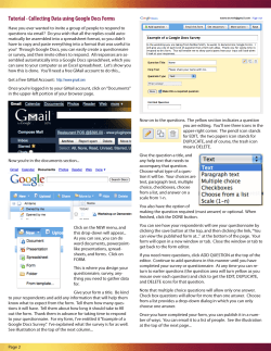


© Copyright 2026