
Sample Submittal
Sample Submittal PROJECT USPS Eagan Boiler Replacement 3165 Lexington Ave S Eagan, MN 55121 MECHANICAL ENGINEER Wentz Associates, Inc. 7225 Ohms Lane Minneapolis, MN 55439 MECHANICAL CONTRACTOR Master Mechanical 1027 Gemini Road Eagan, MN 55121 EQUIPMENT Fulton Vantage Boiler Skid Schebler P4 Exhaust Venting Schebler P2 Intake Piping MANUFACTURER’S REPRESENTATIVE Ryan Company 3361 Republic Avenue Saint Louis Park, MN 55426 Phone (952) 915-6475 Fax (952) 915-6480 Job: USPS Eagan Boiler Replacement - Eagan, MN Model: VTG6000 Qty: Four (4) Type: Hot Water Design Pressure: 160 PSI Relief Valve Setting: 30 PSI Fuel: Natural Gas #2 Oil Inlet Gas Pressure: 5# Firing Control: Modulating (gas) / 2 Stage (oil) Firing Rate: 6000 MBH Voltage: 460/3/60 Standard Features x Built and Certified to ASME Code x Certified to UL 795 x CSD-1 Controls and Gas Train x Factory Assembled Fuel Train x Full Modulation for Natural Gas x Fully Insulated Pressure Vessel x Factory Assembled Fuel Train x Main Gas Pressure Regulator x CSD-1 Approved Manual Ball Valve x Adjustable Operating Temperature Control x High Temperature Control w/ Manual Reset x Low Water Cut Off Probe x Control Circuit Transformer x Linkageless Controls – Siemens LMV Optional Equipment Included x Condensate Drain Kit (One per 12,000,000 BTU/HR) x PH Neutralization Kit (One per Condensate Drain Kit) x 1-5PSI Gas Pressure Reducing Regulator x ModSync LX Sequencing Controller o Color Screen o BacNet BMS Integration o Return Temp Sensor o Boiler Isolation Valve Control o Flow Measurement Transducer and Display o Natural Gas Pressure Monitoring o Therm Calculation Additional Information 1. Assumptions:Allcomponentsspecifiedbelowarebasedaroundthefollowing operatingconditionassumptions: o Incominggaspressureat3Ͳ5psi,0.5psiatpointofuse,with100ftequivalentofpipe o Maximumsystemflowof1,800GPM(Threeboilersathighfire,one boilerstandby) o 20degreeFahrenheit T o Workingfluid:Water o Buildingdoorwayentrylimitationof96”height,72”width 2. Four(4)dualͲfuel[naturalgasand#2fueloil]VantageVTGͲ6000DFBoilers mountedontwoskidsystems,withequipmentprimedandpaintedonsteel skidsandincorporatedintoacommonsystem. o Multipleskidswillbeprovided;disassemblywillberequiredforshipment andreassemblyofmechanicalandelectricalcomponentswillbeinthe fieldbyothers.Fultonisnotresponsibleforcostsassociatedwith reassemblyinthefield. o Maximumallowableworkingpressureforthesystemisbaseduponthe lowestratedsystemcomponentsifunder160#.Maximumallowable workingtemperatureforthesystemisbaseduponthelowestrated systemcomponentsifunder210F. o Skiddesignswillbemodularperboilertomeetentrylimitation.Each boilerwillhaveaseparableskid. 3. Eachboilerwillhavethefollowingmechanicalandelectricalcomponents: o Pressuregaugewith6”faceandavariͲangletemperaturegauge mountedonthereturnconnectionandsupplyconnection(2ofeach gaugefor4gaugestotalperboiler). 1. Allgaugestofacedownwardwherenoobstructionsarepresent. o Amanual6”butterflyvalveonboththesupplyandreturnwater connectionsforatotaloftwo(2)manualvalvesperboiler. o Amotorized6”butterflyvalveonthesupplywaterconnection. 1. LugStyleButterflyvalvewithCastIronbody,SSTdisc,EPDMseat, and120Velectricactuator.NonͲmodulating,poweropenand close. o TheSiemensLMV36controllerwiredtotheModSyncforindividual temperatureandpressureinformation. o AB&G6”tripledutyvalveonthereturnwaterconnection. o 6”Wyestrainerwith¾”NPTBallValveandGHT(gardenhosethread) adapterupstreamofthereturnwaterconnection. o A6”x12”flexpipeonthereturnandsupplywaterconnectionsfora totaloftwo(2). 4. Forthegroupofboilersthefollowingwillbeprovided: o AcommonheaderfortheFultonsystemhotwatersupplyandreturn: 1. Headerforfour(4)VTGͲ6000DFboilerssizedat10”sch40carbon steelpipewithflangedconnectionsbasedontheassumptions statedabove. 2. ThehotwatersupplyheaderwillbefittedwithavariͲangle temperaturegaugeandthermowellwiredtotheModSync controller. 1. Temperaturegaugetobeangleddownward. 3. The10”sch40returnwaterheaderwillbefittedwithavariͲangle temperaturegaugeandthermowellwiredtotheModSync controller. 1. Temperaturegaugetobeangleddownward. 4. Theskidisdesignedintwosections,“SkidA”and“SkidB”,which willrequirereassemblyofloosecomponentsandpipinginthe field. 1. A6ftdistanceisassumedbetweenskidAandskidB. 5. AKeleSeriesTFXLflowmeterwithdisplayshippedloose,tobe installedinthefieldbyothers: 1. Twoultrasonictransducersfortransmittingandreceiving ultrasonicbursts. 1. Requiresaminimumof10diametersstraight uninterruptedpipeinlet,5diametersstraightpipe outlet. 2. Ultrasonictransducersmustbemaintainedwith acousticlubricant. 2. Remotesystemdetachedmeterandscreenmountedin thefieldbyothers. 3. Minimumflowcapabilitymeasuredin10inpipe:25GPM. 4. Maximumflowcapabilitymeasuredin10inpipe:9,700 GPM. 5. Maximumtemperature:185degreesF. 6. Eachskidwillhaveflangedconnectionsbetweenindividualboilers toallowfurtherbreakͲdownforbuildingentry. o Commonsupplyandreturnheaderforfueloilbyothers. o AcommonheaderfornaturalgassupplytotheVTGͲ6000DFboilers, pipedtotheinletofeachfueltrain. 1. Naturalgasheadersizedat4”carbonsteelwith150#flanged connectionsbasedonthegasassumptionsstated:3Ͳ5psi incoming,0.5pou,100ftequivalentpipeforamaxcapacityof 101,553Ͳ144,098SCFH. 2. SierraInstrumentsBoilerTraknaturalgasflowmeterwithdigital display: 1. 2. 3. 4. Thermalmassflowmeter Two(2)4”ballvalvesforflowmeterservicingpurposes One(1)4”bypassballvalve,foratotalofthree(3). Requiresaminimumof25diametersuninterrupted upstreamstraightpipeflow,and10diameters uninterrupteddownstreamstraightpipeflow. 3. A2.5”x12”flexpipe,unionandisolationvalvetobeprovidedin theindividualconnectionstoeachboiler. 4. Thenaturalgasheaderwillbefittedwithapressuretransducer wiredtotheModSynccontroller,andapressuregauge. 5. Thesystemwillhavethefollowingelectricalcomponents: o One(1)fusedexternaldisconnectforthetotalsystemwiredtoallboilers. o NonͲfuseddisconnectsforeachboiler. o ElectricalwiringbetweenskidAandBtobeperformedinthefieldby others. 6. ModSyncLXController o Intelligentsolutionforcontrolandsequencingofmultipleboilersystems o 12.1”ColorTouchScreen o OutdoorReset o DataTrending o Wiredinthefieldbyotherstocommunicatedataand/orcontrolthe following: 1. Naturalgaslinepressuretransducer 2. SiemensLMVsoneachboiler 3. Motorizedbutterflyvalveoneachboiler 4. Supplywaterthermowell 5. Returnwaterthermowell 6. Flowmeasurementtransducer(shippedloose,installedinthe fieldbyothers) 7. Pressuretransducerinsystem(Suppliedandinstalledbyothers) 8. BuildingManagementSystem 9. Naturalgasflowmeter 7.Expansiontankandairseparatortobeprovidedbyothers. o AirseparatorisrequiredforFultonequipment Condensing Hydronic Boilers 2,000,000 - 6,000,000 BTU/HR The heat transfer innovators. EngineeringData SupplementalTechnicalData VantageHydronicCondensingBoilers Model:VTGͲ6000DF,RielloBurner Category Fuel Units Input BTU/HR KCAL/HR BTU/HR1200Fin–1400Fout KCAL/HR490CinͲ600Cout FT3/HR M3/HR FT3/HR M3/HR GPH LPH MaximumInͲrushAmps withStandard7.5HPBlower Motor Output FuelConsumptionatrated capacity–NaturalGas FuelConsumptionatrated capacityͲPropane FuelConsumptionatrated capacityͲ#2Oil ElectricalRequirements** x 208/60/3 x 230/60/3 x 460/60/3 MaximumAllowableWorking Pressure MaximumAllowableWorking Temperature WaterContent Connection SafetyValveInlet(160PSIG) SafetyValveOutlet(160PSIG) WaterInletandOutlet AirInlet NaturalGasInlet PropaneInlet #2OilConnections ExhaustOutlet*** Detail NaturalGas,Propane,#2Oil,BͲ100 Biodiesel* 6,000,000 1,512,986 5,640,000 1,422,207 6,000 170 2,334 66.1 42.8 162.0 32.5 28.2 14.6 PSI BAR DegreesF DegreesC Gallons Liters 160 11.0 210 99 480 1,817 Units IN MM Diameter 1 25.4 IN MM IN MM 1¼ 31.75 6 152.4 IN MM IN MM IN MM IN MM IN MM 12 304.8 2.5 63.5 2 51 .5 12.7 14 355.6 *Consultfactory **Contactfactoryforothervoltages ***FluepipingmustbeCategoryIV(PositivePressure,Condensing) Category DryWeight Units LB KG LB KG LB KG LB/FT2 KG/M2 ShippingWeight OperatingWeight FloorLoading Weight 9355 4243 9700 4400 13,903 6,306 269 1313 GasPressureRequirements: x NaturalGasFiring–1PSIG–5PSIGrequiredatthefueltraininlet. x LowerIncomingGasPressures:ConsultFactoryforAdditionalInformation. x MaximumSuctiontoBoilerMountedOilPump13Hg. x MaximumFlowandReturnPresssuretoOilPump3PSI. OtherTechnicalData: x BoilerratedHP:179BHP,1758KW x TurndownRatios:5:1NaturalGas o Refertofactorytestfiresheetforsitespecificsettings. x SafetyReliefValveTrimPressuresAvailable:30PSIG,60PSIG,75PSIG,100PSIG,125PSIG,160PSIG o Additionaltrimpressuresareavailable.Consultfactoryforadditionalinformation. x JacketLosses:0.2%ofoutputatHighFire,IAWASHRAEStandard103Ͳ2007 x ExhaustFlowRate:Willvarybasedonstacktemperatureandfiringrate o SCFM1373 o ACFM1725 EmissionsData(typical): NOx CO2 VTGͲ6000NatGas 30ppm 9.4% VTGͲ6000#2Oil 100ppm 12.5% x VOC=VolatileOrganicCompounds x CalculationsbasedonEPAPM10AP42Standard x NOxisbasedona3%O2correction x ConsultfactoryforNOxrequirements<30ppm VOC 0.0330lbs/hr 0.0338lbs/hr CO <50ppm <50ppm StandardControlPlatform:SiemensLMV36(FlameProgrammer),YokogawaUT32A(TemperatureControl) FultonHeatingSolutions,Inc. 972CentervilleRoad,Pulaski,NY13142 Phone:(315)298Ͳ5121•Fax:(315)298Ͳ6390 www.fulton.com vtg6000dfͲengdataͲtechdata dŚĞƌŵ ŵĂůĨĨŝĐŝĞŶĐLJƵƌǀĞƐ ŶŐŝŶĞĞƌŝŶŐŐĂƚĂ sĂŶƚĂŐĞ,LJĚ ĚƌŽŶŝĐŽŶĚĞŶƐŝŶŐŽŝůĞƌƐ DŽĚĞů͗sd'ͲϲϬϬϬ dŚĞƌŵĂůĨĨŝĐŝĞŶĐLJ͕ WĞƌĐĞŶƚ ϭϬϬ ϵϵ ϵϴ ϵϳ ϵϲ ϵϱ ϵϰ ϵϯ ϵϮ ϵϭ ϵϬ ϴϵ ϴϴ ϴϳ ϴϲ ϮϬй/ŶƉƵƚ ϰϬй/ŶƉƵƚ ϲϬй/ŶƉƵƚ ϴϬй/ŶƉƵƚ ϭϬϬй/ŶƉƵƚ ϴϬ ϭϬϬ ϭϮϬ ϭϰϬ ZĞƚƵƌŶtĂƚĞƌ dĞŵƉĞƌĂƚƵƌĞ͕Ž&͕ϮϬŽ&dĞŵƉĞƌĂƚƵƌĞŝĨĨĨĞƌĞŶƚŝĂů ϭϲϬ EŽƚĞƐ͗ ϭ͘ &ƵĞůŝƐŶĂƚƵƌĂůŐĂƐ͘ ďƚĂŝŶĞĚƵƐŝŶŐƚŚĞŵĞƚŚŽĚŽůŽŐLJĨƌŽŵƚŚĞd^ͲϮϬϬ ϬϬƚĞƐƚƉƌŽĐĞĚƵƌĞƐ͘ Ϯ͘ dŚĞƌŵĂůĨĨŝĐŝĞŶĐLJǀĂůƵĞƐŽď ϯ͘ dŚĞƌĞĂƌĞƚǁŽŵĂũŽƌĐŽŶĚŝƚŝŽŶƐŽĨĂďŽŝůĞƌŽƉĞƌĂƚŝŶŐǁŚŝĐŚĚŝƌĞĐƚůLJĂĨĨĞĐƚƚŚĞƌŵĂůĞĨĨŝĐŝĞŶĐLJ͘ Ă͘ ZĞƚƵƌŶtĂƚĞƌdĞŵƉĞƌĂƚƵƌĞ͗ƐƌĞƚƵƌŶǁĂƚĞƌƚĞŵƉĞƌĂƚƵƌĞĚĞĐƌĞĂƐĞƐ͕ƚŚĞƌŵĂůĞĨĨŝĐŝĞŶĐLJŝŶĐƌĞĂƐĞƐ͘ ď͘ &ŝƌŝŶŐZĂƚĞ;й/ŶƉƵƚͿͿ͗ƐĨŝƌŝŶŐƌĂƚĞĚĞĐƌĞĂƐĞƐ͕ƚŚĞƌŵĂůĞĨĨŝĐŝĞŶĐLJŝŶĐƌƌĞĂƐĞƐ͘ &Ƶ ƵůƚŽŶ,ĞĂƚŝŶŐ^ŽůƵƚŝŽŶƐ͕/ŶĐ͘ ϵϳ ϳϮĞŶƚĞƌǀŝůůĞZŽĂĚ͕WƵůĂƐŬŝ͕EzϭϯϭϰϮ WŚ ŚŽŶĞ͗;ϯϭϱͿϮϵϴͲϱϭϮϭͻ&Ădž͗;ϯϭϱͿϮϵϴͲϲϯϵϬ ǁǁǁ͘ĨƵůƚŽŶ͘ĐŽŵ ǀƚŐϲϬϬϬͲĞĨĨĐƵƌǀĞͲĞŶŐĚĂƚĂͲϮϬϭϭͲϵϮϮ &ůƵĞ'ĂƐŽŶĚĞŶƐĂƚĞWƌŽĚƵĐƚŝŽŶ ŶŐŝŶĞĞƌŝŶŐĂƚĂ sĂŶƚĂŐĞ,LJĚƌŽŶŝĐŽŶĚĞŶƐŝŶŐŽŝůĞƌƐ DŽĚĞů͗sd'ͲϲϬϬϬ ϰϱ ϰϬ ϯϱ 'ĂůůŽŶƐƉĞƌ,ŽƵƌ ϯϬ Ϯϱ ϭϬϬй/ŶƉƵƚ ϴϬй/ŶƉƵƚ ϮϬ ϲϬй/ŶƉƵƚ ϰϬй/ŶƉƵƚ ϭϱ ϮϬй/ŶƉƵƚ ϭϬ ϱ Ϭ ϴϬ ϭϬϬ ϭϮϬ ϭϰϬ ϭϲϬ ZĞƚƵƌŶtĂƚĞƌdĞŵƉĞƌĂƚƵƌĞ͕ϮϬΣ dĞŵƉĞƌĂƚƵƌĞŝĨĨĞƌĞŶƚŝĂů EŽƚĞƐ͗ ϭ͘ŽŶĚĞŶƐĂƚĞƉƌŽĚƵĐƚŝŽŶŵĞĂƐƵƌĞŵĞŶƚƐŽďƚĂŝŶĞĚĨƌŽŵƚĞƐƚŝŶŐŝŶ&ƵůƚŽŶZΘůĂďŽƌĂƚŽƌLJ͘ Ϯ͘&ƵĞůŝƐŶĂƚƵƌĂůŐĂƐ͘ &ƵůƚŽŶ,ĞĂƚŝŶŐ^ŽůƵƚŝŽŶƐ͕/ŶĐ͘ ϵϳϮĞŶƚĞƌǀŝůůĞZŽĂĚ͕WƵůĂƐŬŝ͕EzϭϯϭϰϮ WŚŽŶĞ͗;ϯϭϱͿϮϵϴͲϱϭϮϭͻ&Ădž͗;ϯϭϱͿϮϵϴͲϲϯϵϬ ǁǁǁ͘ĨƵůƚŽŶ͘ĐŽŵ ǀƚŐϲϬϬϬͲĞŶŐĚĂƚĂͲĐŽŶĚƉƌŽĚͲϮϬϭϭͲϬϵϭϰ &ůƵĞ'ĂƐdĞŵƉĞƌĂƚƵƌĞ ŶŐŝŶĞĞƌŝŶŐĂƚĂ sĂŶƚĂŐĞ,LJĚƌŽŶŝĐŽŶĚĞŶƐŝŶŐŽŝůĞƌƐ DŽĚĞů͗sd'ͲϲϬϬϬ ϮϱϬ dĞŵƉĞƌĂƚƵƌĞ;Σ&Ϳ ϮϬϬ ϭϬϬй/ŶƉƵƚ ϭϱϬ ϴϬй/ŶƉƵƚ ϲϬй/ŶƉƵƚ ϰϬй/ŶƉƵƚ ϭϬϬ ϮϬй/ŶƉƵƚ ϱϬ ϴϬ ϭϬϬ ϭϮϬ ϭϰϬ ϭϲϬ ZĞƚƵƌŶtĂƚĞƌdĞŵƉĞƌĂƚƵƌĞ͕ϮϬΣ dĞŵƉĞƌĂƚƵƌĞŝĨĨĞƌĞŶƚŝĂů EŽƚĞƐ͗ ϭ͘&ůƵĞŐĂƐƚĞŵƉĞƌĂƚƵƌĞŵĞĂƐƵƌĞŵĞŶƚƐŽďƚĂŝŶĞĚĨƌŽŵƚĞƐƚŝŶŐŝŶ&ƵůƚŽŶZΘůĂďŽƌĂƚŽƌLJ͘ Ϯ͘&ƵĞůŝƐŶĂƚƵƌĂůŐĂƐ͘ &ƵůƚŽŶ,ĞĂƚŝŶŐ^ŽůƵƚŝŽŶƐ͕/ŶĐ͘ ϵϳϮĞŶƚĞƌǀŝůůĞZŽĂĚ͕WƵůĂƐŬŝ͕EzϭϯϭϰϮ WŚŽŶĞ͗;ϯϭϱͿϮϵϴͲϱϭϮϭͻ&Ădž͗;ϯϭϱͿϮϵϴͲϲϯϵϬ ǁǁǁ͘ĨƵůƚŽŶ͘ĐŽŵ ǀƚŐϰϬϬϬͲĞŶŐĚĂƚĂͲĨůƵĞƚĞŵƉͲϮϬϭϭͲϬϵϬϴ tĂƚĞƌ^ŝĚĞWƌĞƐƐƵƌĞƌŽƉƵƌǀĞ ŶŐŝŶĞĞƌŝŶŐĂƚĂ sĂŶƚĂŐĞ,LJĚƌŽŶŝĐŽŶĚĞŶƐŝŶŐŽŝůĞƌƐ DŽĚĞů͗sd'ͲϲϬϬϬ ϭϰ ϭϮ WƌĞƐƐƵƌĞƌŽƉ͕W^/ ϭϬ ϴ ϲ ϰ Ϯ Ϭ Ϭ ϱϬ ϭϬϬ ϭϱϬ ϮϬϬ ϮϱϬ ϯϬϬ ϯϱϬ ϰϬϬ ϰϱϬ ϱϬϬ ϱϱϬ ϲϬϬ ϲϱϬ &ůŽǁ͕'WD EŽƚĞƐ͗ ϭ͘ ƐƚŚĞĨůŽǁƌĂƚĞŽĨƚŚĞŚĞĂƚƚƌĂŶƐĨĞƌŵĞĚŝƵŵŝŶĐƌĞĂƐĞƐ͕ƉƌĞƐƐƵƌĞĚƌŽƉŝŶĐƌĞĂƐĞƐ͘ Ϯ͘ WƌĞƐƐƵƌĞĚƌŽƉǀĂůƵĞƐŶŽƚĞĚĂƉƉůLJƚŽϭϬϬйǁĂƚĞƌĂŶĚƵƉƚŽϱϬйĞƚŚLJůĞŶĞŽƌƉƌŽƉLJůĞŶĞŐůLJĐŽů͘ ϯ͘ /ƚŝƐƉŽƐƐŝďůĞƚŽŽƉĞƌĂƚĞƚŚĞsĂŶƚĂŐĞďŽŝůĞƌǁŝƚŚĨůŽǁƌĂƚĞƐŽƵƚƐŝĚĞƚŚĞƌĂŶŐĞŽĨǀĂůƵĞƐƐŚŽǁŶŽŶƚŚŝƐĐŚĂƌƚ͘ ŽŶƐƵůƚƚŚĞĨĂĐƚŽƌLJĨŽƌĨƵƌƚŚĞƌĚĞƚĂŝůƐ͘ &ƵůƚŽŶ,ĞĂƚŝŶŐ^ŽůƵƚŝŽŶƐ͕/ŶĐ͘ ϵϳϮĞŶƚĞƌǀŝůůĞZŽĂĚ͕WƵůĂƐŬŝ͕EzϭϯϭϰϮ WŚŽŶĞ͗;ϯϭϱͿϮϵϴͲϱϭϮϭͻ&Ădž͗;ϯϭϱͿϮϵϴͲϲϯϵϬ ǁǁǁ͘ĨƵůƚŽŶ͘ĐŽŵ ǀƚŐϲϬϬϬͲƉƌĞƐƐĚƌŽƉͲĞŶŐĚĂƚĂͲϮϬϭϭͲϭϭϬϵ CUSTOMER CONNECTIONS ITEM DESCRIPTION SIZE TYPE A WATER SUPPLY 10" 150# B 10" 150# C WATER RETURN CONDENSATE DRAIN (4X) 1" N.P.T. D FUEL SUPPLY 3" 150# E ELECTRICAL --- --- NOTES: 1. LOCAL CODE OR SEISMIC RESTRAINT MAY REQUIRE ADDITIONAL FIELD SUPPORTS. THESE SUPPORTS ARE TO BE ADDED IN THE FIELD BY OTHERS. 2. 36" CLEARANCE REQUIRED FOR ELECTRICAL PANELS. PLEASE REFER TO THE O&M MANUAL FOR ADDITIONAL INFORMATION REGARDING CLEARANCES AND INSTALLATION INSTRUCTIONS. B 3. FLUE GAS CONDENSATE PIPING TO BE INSTALLED IN THE FIELD BY OTHERS. CONDENSATE DRAIN AND PH NEUTRALIZATION KITS TO BE SHIPPED LOOSE. 12 3/4 4. ADDITIONAL PIPING AND ELECTRICAL WIRING NEEDED TO BE SUPPLIED AND INSTALLED BY OTHERS. 5. ALL GAS AND OIL PIPING TO BE LEAK TESTED AND ADJUSTED IN THE FIELD BY OTHERS. 6. UNLESS OTHERWISE NOTED, PIPING COMPONENTS AND FABRICATION WILL BE TO FULTON STANDARDS. IF PIPING CODES SUCH AS B31.1, B31.3, B31.9, OR OTHER CUSTOM SPECIFICATIONS APPLY, PLEASE CONTACT THE FACTORY FOR PRICING AND AVAILABILITY. 189 15/16 7. OIL PIPE ACCESSORIES TO BE SHIPPED LOOSE AND INSTALLED IN THE FIELD BY OTHERS. ALL OTHER PIPING, FITTINGS, AND ADAPTERS BY OTHERS. A 8. SAFETY RELIEF VALVES SHIPPED LOOSE, PIPING BY OTHERS. 9. COMMON RETURN AND SUPPLY WATER HEADERS AND NATURAL GAS HEADER TO BE SUPPORTED IN THE FIELD BY OTHERS. 54 10. BOILER SKIDS, GAS PIPING, ELECTRICAL TO BE FIELD ASSEMBLED BY OTHERS. 5 7/8 11. ACCESSORIES, THERMOMETERS, PRESSURE GAUGES, SENSORS, WELLS TO BE SHIPPED LOOSE AND INSTALLED BY OTHERS. 12. ALL DIMENSIONS INSIDE ( ) DENOTE REFERENCE DIMENSIONS. 293 352 11/16 13. ALL DIMENSIONS INSIDE Q DENOTE OVERALL DIMENSIONS. TOP VIEW XX DENOTES FLANGE CONNECTION NUMBER USE NUMBERS STAMPED ON MATCHING FLANGES TO AID IN REASSEMBLY. D 72 1/16 E 166 1/2 158 1/2 139 7/8 117 7/8 78 (TYP. 4 PLCS.) C 2 11/16 155 FRONT VIEW LEFT SIDE VIEW UNLESS OTHERWISE NOTED: A DIMENSIONS ARE IN INCHES TOLERANCES ON UPDATED SKID MATERIALS; ADDED RIGID GAS CONNECTORS, FUEL OIL PUMPS. MLR 11/16/12 FRACTIONS B1/4 (2) PLACE DEC. B.01 (3) PLACE DEC. B.005 ANGLES REV REVISION DESCRIPTION B.O.M. REVISION HISTORY ELEC. ENG MECH. ENG CHECKED APPROVED B2 DEG. SURFACE FINISH 250 MICRO-INCHES This design and drawings are proprietary and are the exclusive property of The Fulton Companies. The corporation does not permit their use except with prior written consent. The items shown in this drawing may be covered by one or more patents of The Fulton Companies. THIRD ANGLE PROJECTION 1 OF 5 DRAWN BY: M.SUMMA MECH. ENG: 8/8/2012 RIGHT SIDE VIEW JOB NUMBER: DESCRIPTION: 463947 (4) VTG-6000DF BOILERS SKID MOUNTED ON (2) SKIDS WITH COMMON WATER AND NATURAL GAS HEADERS CHECKED BY: ELEC. ENG: PROJECT NAME: B.O.M. REVIEW APPROVED BY: PROJECT MANAGER: KDB 8/24/2012 K.BOTTORFF SHEET 1 OF 5 The Fulton Companies 972 Centerville Road Pulaski, New York USA 13142 DRAWING NUMBER V99-0044 R REV A MANUFACTURING B. O. M. 10 9 13 ITEM PART NUMBER 1 60 FRONT ISOMETRIC VIEW 10 9 13 60 REV MANUFACTURING B. O. M. DESCRIPTION QTY U.O.M. ITEM PART NUMBER DESCRIPTION QTY U.O.M. 1-10-000008 10" SCH. 40 PIPE 31.310 ft FT. 36 2-35-000346 3/4-10 HEX NUT, GR.2H 288 EA. 2 1-10-000109 2" X 2" X 1/4" ANGLE STEEL 15.271 ft FT. 37 2-35-000423 4" SCH. 40 WELD ELBOW 2 EA. 3 1-10-000338 1" S.S. SCH. 40 PIPE 8.296 ft FT. 38 2-35-000432 4" WELD TEE 6 EA. 4 2-10-000113 2 1/2" SCH. 40 PIPE 1.333 ft FT. 39 2-35-000440 4" 150# CARBON STEEL SLIP-ON FLANGE 8 EA. 5 2-10-000115 4" SCH. 40 SMLS PIPE 22.519 ft FT. 40 2-35-000452 4" 150# CARBON STEEL BLIND FLANGE 1 EA. 6 2-10-000147 6" SCH. 40 SMLS PIPE 15.333 ft FT. 41 2-35-000472 4" 150# CARBON STEEL WELD-NECK FLANGE 2 EA. 7 2-12-000416 4" 150# ELASTAGRAPH RING GASKET 5 EA. 42 2-35-000478 4" X 2 1/2" C.S. WELD REDUCER (SA-234) 4 EA. 8 2-12-000420 6" 150# ELASTAGRAPH RING GASKET 60 EA. 43 2-35-000551 6" SCH. 40 WELD ELBOW 4 EA. 9 2-22-000058 1/2-13 HEX NUT, GR.2H 4 EA. 44 2-35-000553 6" 150# CARBON STEEL SLIP-ON FLANGE 40 EA. 10 2-22-000059 1/2" MEDIUM LOCK WASHER 4 EA. 45 2-35-000580 6" 150# CARBON STEEL WELD-NECK FLANGE 16 EA. 11 2-22-000067 5/8" MEDIUM LOCK WASHER 40 EA. 46 2-35-000674 10" 150# CARBON STEEL WELD-NECK FLANGE 5 EA. 12 2-22-000068 3/4" MEDIUM LOCK WASHER 288 EA. 47 2-35-000676 10" 150# CARBON STEEL SLIP-ON FLANGE 16 EA. 13 2-22-000100 1/2-13 X 1 1/2" BOLT, GR. 5 4 EA. 48 2-35-000705 1/4" X 6" XH NIPPLE 1 EA. 14 2-22-000128 7/8-9 HEX NUT, GR.2H 132 EA. 49 2-35-000726 10" WELD TEE 8 EA. 15 2-22-000129 7/8" MEDIUM LOCK WASHER 132 EA. 50 2-35-000805 2 1/2" X 14" - NPT STANDARD NIPPLE 4 EA. 16 2-22-000278 3/4-10 X 2" BOLT, GR. 5 192 EA. 51 2-35-001118 3/4" 3000# SOCKET WELD COUPLING 2 EA. 17 2-30-000117 2 1/2" UL GAS / OIL BALL VALVE 4 EA. 52 2-35-001185 1" X 2" - NPT STAINLESS STEEL GR.316L NIPPLE 2 EA. 18 2-30-000219 3/4" Y-STRAINER 4 EA. 53 2-35-001186 1" X 4" - NPT STAINLESS STEEL GR.316L NIPPLE 2 EA. 19 2-30-000220 - 1/4" UL GAS / OIL BALL VALVE 4 EA. 54 2-35-001190 1" X 8" - NPT STAINLESS STEEL GR.316L NIPPLE 2 EA. 20 2-30-000282 - 1/4" FNPT X 1/4" MNPT BALL VALVE CSA 8 EA. 55 2-35-001193 3/4" X 1/4" STAINLESS STEEL GR.316L BUSHING 8 EA. 21 2-30-000343 OIL PRESSURE GAUGE 0-400 PSI 8 EA. 56 2-35-001206 1/4" STAINLESS STEEL GR.316L SQUARE HEAD 4 EA. 22 2-30-000395 3/4" SPRING CHECK VALVE 4 EA. 23 2-30-000398 1/4" 200# M X F BALL VALVE 1 EA. 57 2-35-001221 3/4" X 3/8" STAINLESS STEEL GR.316L BUSHING 8 EA. 24 2-30-000556 THERMOWELL 3/4 IN SW x 1/2 N.P.T. 2 EA. 58 2-35-001406 2" X 3/4" REDUCING BUSHING 4 EA. 25 2-30-004054 6" 150# SURE FLOW STRAINER 4 EA. 59 2-35-001411 3/4" X 2" - NPT STANDARD NIPPLE 4 EA. 26 2-30-005056 3/4" FULL PORT BALL VALVE 8 EA. 60 5-10-004705 SKID JOINT ANGLE 4" LONG 8 EA. 61 9-VTG-006003 VTG-6000 AHRI HYDRONIC BOILER WITH MAXON 3 EA. 1 EA. 2 EA. - - PLUG 2-35-000163 2 1/2" X 3" - NPT STANDARD NIPPLE 4 EA. 28 2-35-000178 1/4" NPT 3000# FULL COUPLING 10 EA. 29 2-35-000179 3/4" NPT 3000# FULL COUPLING 2 EA. 30 2-35-000239 3/4" STD SQUARE HEAD PLUG 2 EA. 31 2-35-000269 1/4" THREADED ELBOW 1 EA. 32 2-35-000291 2 1/2" SCH. 40 UNION 4 EA. 33 2-35-000338 5/8-11 X 3" BOLT, GR. 5, HIGH TEMP 40 EA. 64 2-35-000807 1" STAINLESS STEEL GR.316L UNION 8 EA. 34 2-35-000342 3/4-10 X 3 1/2" BOLT, GR. 5 288 EA. 65 PO# 1" THREADED S.S. TEE 2 EA. 35 2-35-000345 5/8-11 HEX NUT, GR.2H 40 EA. 66 2-35-001067 1" THREADED STAINLESS STEEL ELBOW 6 EA. 67 PO# 10" 150# CARBON STEEL BLIND FLANGE 2 EA. 68 PO# 10" 150# ELASTAGRAPH RING GASKET 11 EA. EA. 2 DETAIL VIEW A 2 88 BURNER LESS GAS TRAIN 62 BURNER LESS GAS TRAIN 63 DIMENSIONS ARE IN INCHES TOLERANCES ON CONNECTORS, FUEL OIL PUMPS. MLR 11/16/12 FRACTIONS B1/4 (2) PLACE DEC. B.01 (3) PLACE DEC. B.005 ANGLES REV REVISION DESCRIPTION B.O.M. REVISION HISTORY ELEC. ENG MECH. ENG CHECKED APPROVED B2 DEG. SURFACE FINISH 250 MICRO-INCHES B91-3919 PH NEUTRALIZER KIT & CONDENSATE DRAIN KIT CONNECTION 69 PO# 10" X 6" C.S. WELD REDUCER (SA-234) 8 70 PO# 3/4" FUSIBLE LINK VALVE (FLV-075/165) 4 EA. 71 2-35-001339 3/4" THREADED BRASS TEE 8 EA. 72 PO# 3/4" NPT X 36" THREADED FLEX HOSE 8 EA. 73 PO# 4" APOLLO BRASS BALL VALVE 3 EA. 74 PO# 6" B&G BALANCING VALVE (CB-6F) 4 EA. 75 PO# 6" X 12" CL150 FLEX CONNECTOR 8 EA. 76 PO# 7/8-9 X 4" BOLT, GR. 5 132 EA. 77 PO# DIXON BRASS THREADED ADAPTER 4 EA. 78 PO# GAS FLOW METER 1 EA. 79 PO# KEYSTONE 222 6" DIA. BUTTERFLY VALVE 12 EA. 80 PO# KEYSTONE MANUAL ACTUATOR LEVER 8 EA. 81 PO# MODSYNC LX 1 EA. PO# OIL FILTER (11BV-MK) 4 EA. 83 PO# P356088 300 SERIES GAUGE 8 EA. 2 84 PO# PLP LOW PRESSURE GAUGE (0-100" WC) 1 EA. 85 PO# VSI 1040 ROTARY ELECTRIC ACTUATOR 4 EA. 86 PO# WINTERS INDUSTRIAL TIM105A THERMOMETER (3 10 EA. 10 EA. 1/2" STEM) 87 The items shown in this drawing may be covered by one or more patents of The Fulton Companies. THIRD ANGLE PROJECTION 2 OF 5 DRAWN BY: M.SUMMA MECH. ENG: 8/8/2012 JOB NUMBER: 463947 CHECKED BY: ELEC. ENG: PROJECT NAME: B.O.M. REVIEW APPROVED BY: PROJECT MANAGER: KDB PO# WINTERS WELD-IN TYPE THERMOWELL FOR 1/4" ELEMENT (.260 BORE) 88 UPDATED SKID MATERIALS; ADDED RIGID GAS VTG-6000 AHRI HYDRONIC BOILER WITH MAXON 82 DETAIL VIEW A A 9-VTG-006003 81 BACK ISOMETRIC VIEW This design and drawings are proprietary and are the exclusive property of The Fulton Companies. The corporation does not permit their use except with prior written consent. B 27 2 UNLESS OTHERWISE NOTED: REV 8/24/2012 K.BOTTORFF SEE ELECTRICAL 100 AMP FUSED DISCONNECT SWITCH 1 EA. DESCRIPTION: (4) VTG-6000DF BOILERS SKID MOUNTED ON (2) SKIDS WITH COMMON WATER AND NATURAL GAS HEADERS SHEET 2 OF 5 The Fulton Companies 972 Centerville Road Pulaski, New York USA 13142 DRAWING NUMBER V99-0044 R REV A 37 5 41 5 73 5 37 A1 38 23 5 28 48 73 28 78 5 5 73 TOP VIEW 38 5 5 38 84 31 39 42 33 4 (309 9/16) 7 11 35 5 38 17 5 32 A2 A3 ISOMETRIC VIEW 39 39 42 33 7 11 35 4 21 17 117 7/8 5 32 A4 A5 39 21 GAS HEADER PIPING GAS HEADER NOTES: 1. GAS HEADER WILL BE DISASSEMBLED FOR SHIPPING, TO BE FIELD ASSEMBLED, AND LEAK TESTED BY OTHERS. 20 26 FRONT VIEW 22 20 39 33 7 5 11 38 5 55 66 54 A6 55 53 11 41 40 32 A8 82 66 A9 39 63 42 57 33 A10 OIL PIPING KIT 64 65 2. CONDENSATE DRAIN PIPING, ACCESSORIES, AND KITS SHIPPED LOOSE, AND TO BE INSTALLED IN THE FIELD BY OTHERS. 3. PIPING TO FLOOR DRAINS ARE TO BE ADDED IN THE FIELD BY OTHERS. 4. FRESH WATER SOURCE PIPING TO BE ADDED IN THE FIELD BY OTHERS. 52 64 DIMENSIONS ARE IN INCHES TOLERANCES ON CONNECTORS, FUEL OIL PUMPS. MLR 11/16/12 B.O.M. REVISION HISTORY 72 19 56 (TYP. 2 PLCS.) UPDATED SKID MATERIALS; ADDED RIGID GAS REVISION DESCRIPTION 72 CONDENSATE DRAIN PIPING FRACTIONS B1/4 (2) PLACE DEC. B.01 (3) PLACE DEC. B.005 ANGLES REV 35 26 3. ONE (1) REPLACEMENT OIL FILTER TO BE SUPPLIED PER BOILER. UNLESS OTHERWISE NOTED: A 11 32 70 2. ONE (1) OIL PIPING KIT TO BE SUPPLIED PER BOILER. 52 7 17 OIL PIPING NOTES: 1. OIL PIPE ACCESSORIES SHOWN TO BE SHIPPED LOOSE AND INSTALLED IN THE FIELD BY OTHERS. ALL OTHER PIPING, FITTINGS, AND ADAPTERS BY OTHERS. 53 4 18 (SHIPPED LOOSE) CONDENSATE DRAIN NOTES: 1. PIPING TO BE STAINLESS STEEL. 35 38 17 57 54 7 33 5 4 71 64 66 39 42 3 64 A7 39 71 3 35 ELEC. ENG MECH. ENG CHECKED APPROVED B2 DEG. SURFACE FINISH 250 MICRO-INCHES This design and drawings are proprietary and are the exclusive property of The Fulton Companies. The corporation does not permit their use except with prior written consent. The items shown in this drawing may be covered by one or more patents of The Fulton Companies. THIRD ANGLE PROJECTION 3 OF 5 DRAWN BY: M.SUMMA MECH. ENG: 8/8/2012 JOB NUMBER: DESCRIPTION: 463947 (4) VTG-6000DF BOILERS SKID MOUNTED ON (2) SKIDS WITH COMMON WATER AND NATURAL GAS HEADERS CHECKED BY: ELEC. ENG: PROJECT NAME: B.O.M. REVIEW APPROVED BY: PROJECT MANAGER: KDB 8/24/2012 K.BOTTORFF SHEET 3 OF 5 The Fulton Companies 972 Centerville Road Pulaski, New York USA 13142 DRAWING NUMBER V99-0044 R REV A 67 46 76 68 15 14 49 1 47 47 76 68 15 14 1 B1 49 F7 1 47 76 B2 68 15 14 1 B3 F6 47 E7 F5 F4 TOP VIEW B4 F3 B5 E6 F2 47 76 E5 68 15 14 1 49 E4 F1 ISOMETRIC VIEW 47 E3 1 E2 47 76 B6 E1 68 15 14 1 B7 DETAIL VIEW B 47 49 D7 SUPPLY WATER PIPING 1 69 (281 7/8) 52 1/2 124 9/16 52 7/16 D6 45 79 36 36 8 8 80 D5 6 D4 34 D3 44 D2 76 15 14 C8 C6 75 44 C4 34 C3 D1 68 B9 C5 158 1/2 47 B10 B8 16 47 ADDITIONAL TAPPING THERMOWELL THERMOMETER C2 6 85 44 79 79 87 44 6 28 16 DETAIL VIEW B (TYP. 4 PLCS.) DIMENSIONS ARE IN INCHES TOLERANCES ON UPDATED SKID MATERIALS; ADDED RIGID GAS CONNECTORS, FUEL OIL PUMPS. MLR 11/16/12 FRACTIONS B1/4 (2) PLACE DEC. B.01 (3) PLACE DEC. B.005 ANGLES REVISION DESCRIPTION B.O.M. REVISION HISTORY ELEC. ENG MECH. ENG CHECKED 83 44 34 8 12 2. HEADER SUPPORT IN THE FIELD BY OTHERS TO ENSURE NO COMPRESSION OR TENSION OF FLEX CONNECTORS. 36 3. HYDRONIC PIPING INSULATION IN THE FIELD BY OTHERS. UNLESS OTHERWISE NOTED: REV C1 NOTES: 1. MOTORIZED VALVE ACTUATORS WIRED IN THE FIELD BY OTHERS. FRONT VIEW A 86 APPROVED B2 DEG. SURFACE FINISH 250 MICRO-INCHES This design and drawings are proprietary and are the exclusive property of The Fulton Companies. The corporation does not permit their use except with prior written consent. The items shown in this drawing may be covered by one or more patents of The Fulton Companies. THIRD ANGLE PROJECTION 4 OF 5 DRAWN BY: M.SUMMA MECH. ENG: 8/8/2012 JOB NUMBER: DESCRIPTION: 463947 (4) VTG-6000DF BOILERS SKID MOUNTED ON (2) SKIDS WITH COMMON WATER AND NATURAL GAS HEADERS CHECKED BY: ELEC. ENG: PROJECT NAME: B.O.M. REVIEW APPROVED BY: PROJECT MANAGER: KDB 8/24/2012 K.BOTTORFF SHEET 4 OF 5 The Fulton Companies 972 Centerville Road Pulaski, New York USA 13142 DRAWING NUMBER V99-0044 R REV A 47 29 87 30 86 24 51 46 47 76 G1 68 15 14 1 49 46 G3 47 76 G2 68 15 14 L7 L6 L5 1 G5 47 G4 76 K7 TOP VIEW 47 68 15 14 1 K6 49 K5 46 47 76 L4 68 G6 15 ISOMETRIC VIEW 14 1 G7 49 46 L3 G9 K4 L2 L1 (279 1/4) G8 67 76 68 15 14 16 J7 K3 J6 K2 J5 45 69 G10 79 44 H7 52 1/2 124 9/16 52 1/2 35 3/16 DETAIL VIEW C K1 6 75 H6 44 H5 RETURN WATER PIPING J4 139 15/16 J2 59 J1 34 8 36 12 34 8 36 12 8 36 12 34 8 36 12 6 44 25 J3 25 16 H4 34 74 H3 DETAIL VIEW D 26 H2 77 H1 86 45 43 87 83 44 DETAIL VIEW D 45 NOTES: BACK VIEW 1. HEADER SUPPORT IN THE FIELD BY OTHERS TO ENSURE NO COMPRESSION OR TENSION OF FLEX CONNECTORS. 36 12 8 A DIMENSIONS ARE IN INCHES TOLERANCES ON UPDATED SKID MATERIALS; ADDED RIGID GAS CONNECTORS, FUEL OIL PUMPS. MLR 11/16/12 FRACTIONS B1/4 (2) PLACE DEC. B.01 (3) PLACE DEC. B.005 ANGLES REV REVISION DESCRIPTION B.O.M. REVISION HISTORY ELEC. ENG MECH. ENG CHECKED APPROVED B2 DEG. SURFACE FINISH 250 MICRO-INCHES This design and drawings are proprietary and are the exclusive property of The Fulton Companies. The corporation does not permit their use except with prior written consent. The items shown in this drawing may be covered by one or more patents of The Fulton Companies. THIRD ANGLE PROJECTION 5 OF 5 DRAWN BY: M.SUMMA MECH. ENG: 8/8/2012 DESCRIPTION: 463947 (4) VTG-6000DF BOILERS SKID MOUNTED ON (2) SKIDS WITH COMMON WATER AND NATURAL GAS HEADERS ELEC. ENG: PROJECT NAME: B.O.M. REVIEW APPROVED BY: PROJECT MANAGER: KDB 8/24/2012 K.BOTTORFF 36 12 (TYP. 4 PLCS.) JOB NUMBER: CHECKED BY: 8 DETAIL VIEW C 2. HYDRONIC PIPING INSULATION IN THE FIELD BY OTHERS. UNLESS OTHERWISE NOTED: 34 34 SHEET 5 OF 5 The Fulton Companies 972 Centerville Road Pulaski, New York USA 13142 DRAWING NUMBER V99-0044 R REV A 7 A 21 Display and Operating Units A 542 23 AZL2... The AZL2... display and operating units are designed for use with LMV2… / LMV3… and LME39… burner controls, either directly on the burner or in control panels installed close to the burner. x x x The units are used for the display, operation and parameterization of specific safety- and non-safety-related burner functions Key plant data and fault codes can be queried and displayed Communication between AZL2… and burner control takes place via BCI interface The AZL2... and this Data Sheet are intended for use by OEMs which integrate the display and operating units in their products! CC1N7 42en 9. 1.2 7 Building Technologies HVAC Products Dimensions imensions in mm 3 , 4 27,4 21... 2 A 1 7 9 7 42m 1 11 A 12,4 23... 9 29, 7 42m 3 4 9,4 9 1 9,4 ¤ 2 7 Siemens uilding Technologies Sub ect to alteration uilding Technologies AC Products AC Products mb 11 11 CC1N7 42en 9. 1.2 7 LMV36... AGM60... LMV36.520A1 / AGM60.4A9 Basic unit with integrated fuel-air ratio control for forced draft burners Basic Documentation The LMV36... / AGM60... and this Basic Documentation are intended for OEMs which integrate the units in their products! Software version V03.10 CC1P7544en 08.12.2009 Building Technologies HVAC Products 5 Dimensions 5.1 LMV36... Dimensions in mm 230 202 192 141 82,5 135 122 118,5 100,8 118,5 53,6 76,6 25,5 16,5 39,3 22,8 17,3 10,2 R100 12,5 23,5 27,2 82,5 128,5 172 202 60 19,7 19,5 217 Figure 11: LMV36... dimensions 39/242 Building Technologies HVAC Products Basic documentation LMV36... 5 Dimensions CC1P7544en 08.12.2009 <<Contents>> <<Index>> General Specifications UT35A/UT32A Digital Indicating Controllers GS 05P01D31-01EN [Style: S2] Overview The UT35A/UT32A digital indicating controllers employ an easy-to-read, 14-segment large color LCD display, along with navigation keys, thus greatly increasing the monitoring and operating capabilities. A ladder sequence function is included as standard. The short depth of the controller helps save instrument panel space. The UT35A/UT32A also support open networks such as Ethernet communication. Features • A 14-segment, active (PV display color changing function) color LCD display is employed. Two five-digit, high-resolution displays are possible. Alphabet letters can be displayed in an easy-to-read manner. The guide display shows parameter names. • Easy to operate Navigation keys (SET/ENTER and Up/Down/Left/ Right arrow keys) are employed to facilitate making settings. • 65 mm depth The small depth enables the mounting in a thin and small instrumented panel. • Ladder sequence function is included as standard. This function allows for creating a simple sequence control. Dedicated LL50A Parameter Setting Software (sold separatly) allows for performing programming using a ladder language. • Various built-in open network functions such as Ethernet are available. Easy connection with various vendors’ PLCs is possible. • Quick setting function Setting only the minimum necessary parameters for operation is possible. • Equipped with a multitude of functions Universal I/O are included as standard. PID control, heating/cooling control, etc. are available. UT35A UT32A Table of Number of Inputs and Outputs Model and suffix code (See the model code) Number of analog input points Number of analog output points (*1) Number of contact input points Number of contact output points (*3) -×0× -×1× -×2× 1 1 1 1 1 1 (*2) 2 4 7 3 5 8 -×0× -×1× -×2× 1 1 1 1 1 1 (*2) 2 2 4 3 3 5 UT35A UT32A *1: *2: *3: Excluding control output In the case of cooling control output is analog output, it can not be used for transmission output. Excluding control output relays Functional Specifications Control Computation Function Control Specifications (1) Types of control • PID control • ON/OFF control (*4) • Two-position two-level control (*5) • Heating and cooling control (*5) (1) Control Mode Single-loop control (2) Control period 200 ms *4: *5: Not selectable for Position proportional type Selectable for heating and cooling control Yokogawa Electric Corporation 2-9-32, Nakacho, Musashino-shi, Tokyo, 180-8750 Japan Tel.: 81-422-52-7179 Fax.: 81-422-52-6619 GS 05P01D31-01EN 1st Edition Nov.30, 2009 (KP) 2nd Edition Jun.11, 2010 (KP) What is ModSync? THE NE W STANDARD FOR BOILER SEQUENCING CONTROLS The majority of boiler system designs incorporate multiple boilers to meet heating or process load demands. Part load efficiencies and system redundancy are a few of the factors used in determining the number of boilers in the system. The operating efficiency of each boiler stage will vary based on the type of boiler being used and the system configuration. Maximizing boiler system performance is based on utilizing a control system that understands where the peak boiler efficiencies are gained and controlling each boiler stage as part of the system. The ModSync Sequencing System was designed to do exactly that. ModSync monitors the system demand requirements and then determines the most efficient boiler stage operating mode to meet those demands. A userfriendly, touchscreen interface provides quick access to current system status information. Multiple configuration screens allow key system parameters to be easily located and updated which decreases commissioning time requirements significantly. With an expandable platform, ModSync can be configured to control up to 75 boiler stages from one sequencing system. Why Should I Use ModSync? Key Features BE T TER CONTROL, INCREASED SYSTEM EFFICIENCY UNIQUE QUALITIES OF THE MODSYNC The most popular application for ModSync is integration with multiple condensing boilers. Hydronic systems are configured to maintain building room temperatures on “design days”, thus ensuring there is plenty of heat available during the coldest days of the year. Ease of Use: The ModSync combines What happens if the outdoor temperature is warmer than the design temperature? On these days, the boiler system has too much capacity. The warmer the day, the less boiler capacity is required. Lower hydronic loop temperatures can be used while still maintaining building temperature. This allows for significant efficiency gains during non-peak or “shoulder loads.” The ModSync provides outdoor reset functionality to adjust the hydronic loop temperature setpoint based on the measured outdoor temperature. As the outdoor temperature increases, the ModSync automatically decreases the hydronic loop setpoint. Lower loop temperatures during warmer days allow for significant energy savings while still maintaining building comfort levels. The ModSync provides independent outdoor reset functions based on the building status, Occupied and Unoccupied. Each function has unique user defined variables that determine a linear setpoint value based on the measured outdoor temperature. Condensing Boiler Efficiency LOW FIRING RATE AND RE TURN WATER TEMPERATURE EQUALS EFFICIENCY GAINS Condensing boiler efficiency has two main determining factors: the temperature of the water returning from the system and the BTU firing rate output of the boiler. Increased efficiencies are gained with colder return water temperatures and minimum firing rate levels. ModSync logic has been configured around these principles to maintain peak efficiencies throughout the entire heating season. Thermal Efficiency vs. Return Water Temperature Intelligent Lead/Lag: Optimized logic for boiler lead/lag position keeps a consistent number of cycles/run hours across all stages. Building Integration: The ModSync can be configured to communicate with Energy/Building Management Systems using BACnet, Modbus, Lonworks and many other protocols. Outdoor Reset: The system setpoint is automatically adjusted based on outdoor temperature. Warmer outdoor temperatures lower the hydronic loop setpoint, increasing system efficiency. Multiple Setpoint Modes: Easily select between ModSync Outdoor Reset, Remote Setpoint (4-20mA, 0 –10VDC), E/ BMS Communication or Manual setpoint modes through the ModSync touchscreen. Setback Scheduling: The loop setpoint can be configured to change based on occupancy of the building. This allows for automatic switch over to lower operating temperatures during off hours such as nights, weekends and holidays. System Interface Flexibility: The ModSync can be custom programmed by in-house specialists to match your most demanding system design requirements, eliminating “canned logic” limitations. Trending: Key variables such as Supply Temperature, Return Temperature and Setpoint can be trended to show system response and performance data. 100 99 98 Thermal Efficiency, Percent sophisticated control capabilities with a user-friendly interface. 97 96 20% Input 95 40% Input 94 60% Input 93 80% Input 92 100% Input 91 5:1 turndown typical 90 89 88 87 86 80 100 120 140 160 Return Water Temperature, °F, 20°F Temperature Differential 180 Alarm Status and History: Alarm conditions are easily communicated with an icon display and text description of the current alarm. The Alarm History provides a date and time stamp of any recent alarm conditions. Remote Monitoring: Addition of an inSite interface option allows remote monitoring and adjustment of the ModSync using any web enabled device. Smartphone compatibility provides another solution for monitoring system variables. ELECTRIC ACTUATORS VSI-1000 SERIES TM DESCRIPTION VSI-1000 Series Electric Actuators are used on Kele KBV Series butterfly valves to provide two-position (with or without battery backup) or proportional control in a NEMA 4X housing. The VSI-1000 Series comes standard on 8" and larger non-spring return assemblies and on 5" and larger twoposition spring return assemblies. They can be ordered on smaller valve assemblies as an option. Standard features include 2 SPDT fully adjustable auxiliary switches (two-position only), manual override crank, and an internal heater to prevent condensation in outdoor installations. KBV-2-6-E2SO assembly includes VSI-BB1020 actuator SPECIFICATIONS FEATURES • • • • • • • • • • Lightweight, compact design Two-position or modulating control Two-position battery-backed models NEMA 4X watertight, corrosion-resistant housing Integral position indicator Space heater standard Two 1/2" conduit connections Detachable manual override crank Terminal strip wiring Worm gear drive, no electro-mechanical brake required • Mounting orientation in any direction • 4-20 mA or 500 Ω optional feedback signal • Two SPDT fully adjustable auxillary switches on two-position models Power 120 VAC standard Models 1005 to 1020 12/24 VDC optional Models 1005 to 1040 24 VAC optional Torque range 347-17,359 in-lb Motor 120 VAC, 1 phase, 60 Hz; enclosed, non-ventilated, high starting torque, reversible induction, Class E insulation Thermal overload Auto reset, embedded Travel limit switches Cam operated, adjustable SPDT for open/close stop Position indicator High-visibility graduated dial Conduit connections Two 1/2" NPT Gears Alloy steel rear, al-bronze sector Bearings Alloy steel sleeve and ball Ambient temp -31° to 150°F (-35° to 65°C) Approvals CSA-NRTL/C, NEMA 4, 4X ACTUATOR SPECIFICATIONS VSI-1000 Series Two-Position Actuators (models with BB prefix are battery backed) Model 1005 Torque (in-lb) 347 Nm 39 Duty cycle 100% Travel speed 12.5 @ 60 Hz (sec) Max current 0.35/0.18 (amp @ 120/240 VAC) Weight lb (kg) 4.4 (2) 1010 1040 1060 868 98 100% 25 1020/ BB1020 1736 196 100% 25/7.5 3472 392 80% 25 5208 588 75% 25 1100/ BB1100 8680 980 50% and 80% 25/7.5 0.41/0.22 1.25/0.70 1.66/0.90 1.62/0.88 2.23/1.21 2.33/1.17 2.40/1.21 8.8 (4) 17.2 (8)/ 22.3 (10) 18.7 (8.5) 44 (20) 46. 2 (21)/ 56.3 (25.5) 48.4 (22) 52.8 (24) KELE • www.kele.com • FAX 800-284-5353 1150 1200 13,019 17,359 1471 1961 50% and 80% 50% and 80% 37.5 50 USA 888-397-5353 • International 901-382-6084 March 2006 ACTUATOR SPECIFICATIONS (CONTINUED) VSI-1000S Series Modulating Actuators (battery backup not available ) Model Torque (in-lb) Nm Resolution Power consumption (VA) Power @ rest Duty cycle Travel speed @ 60 Hz (sec) Max current (amp @ 120/240 VAC) Weight (lb) 1010S 868 98 1020S 1736 196 1040S 1060S 1100S 3472 5208 8680 392 588 981 1/100 - 1/400 steps through 90° 200 350 350 2 VA 80% 75% 80% 25 25 25 1150S 13,019 1471 1200S 17,359 1961 70 200 350 350 100% 25 80% 12.5 80% 37.5 80% 50 0.65/0.35 1.8/0.9 1.8/0.9 1.62/0.88 2.8/1.4 3.4/1.7 – 9.7 (4.4) 18 (8) 18 (8) 44 (20) 48.4 (22) 48.4 (22) 50.6 (23) WIRING N L - IN + - OUT + N 120 VAC Control L1 110 VAC 4-20 mA Aux Cont. 4-20 mA 1 2 3 4 5 6 7 Power Open Close 120 VAC Control Input Open Close 1 2 3 4 5 6 L C2 7 N INT 8 G C3 9 COM NO 10 Open NC 11 Close Close to defeat failsafe on power outage Contact Out CAM Adjusted HTR VSI-1000 Two-Position/Tri-State VSI-1000 4-20 mA or 1-5 VDC L1 N G VSI-BB1020, BB1100 Two-Position DIMENSIONS A in (cm) B F G L1 C L2 D E Side View Dimension A B C D E F G L1 L2 1005 1010/1010S 3.2 (8.3) 2.9 (7.6) 1.1 (2.9) 2.9 (7.5) 0.5 (1.2) 2.5 (6.4) 2.0 (6.4) 2.7 (6.8) 2.4 (6.0) 3.8 (9.8) 4.3 (11.0) 1.4 (3.5) 3.7 (9.5) 0.7 (1.7) 2.7 (8.8) 2.1 (8.8) 3.2 (8.2) 2.8 (7.0) Bottom View 1060/1060S 1020/1020S/BB1020 1100/1100S/BB1100 1040/1040S 7.1 4.8 (18.2) (12.3) 7.9 5.5 (20.0) (13.4) 1.0 1.3 (2.6) (3.3) 5.7 4.3 (14.5) (10.8) 1.2 1.0 (3.0) (2.7) 5.4 3.7 (9.4) (9.4) 4.1 2.5 (10.5) (9.4) 5.4 4.6 (13.6) (11.8) 4.6 3.3 (11.6) (8.4) 1150/1150S 1200/1200S 7.1 (18.2) 7.9 (20.0) 1.0 (2.6) 5.7 (14.5) 1.2 (3.0) 5.8 (15.9) 4.1 (10.5) 5.4 (13.6) 4.6 (11.6) ORDERING INFORMATION VSI-1000 Series comes standard with Kele KBV Series butterfly valves. Can be ordered separately for custom retrofit applications. Consult Kele. KELE • www.kele.com • FAX 800-284-5353 USA 888-397-5353 • International 901-382-6084 YF150 / YF150SS - Cast Steel / Cast 316 Stainless Steel C la s s 15 0 Flanged End Connect ions Sure Flow Class 150 ASME Flanged A strainers are available in Carbon Steel and Stainless Steel. A machined, tapered seat ensures a perfect fit for the removable, stainless steel B screen. Size 2” and larger come complete with flanged blow-off cover, gasket & plug. 1 1/2” and smaller come complete with solid threaded cover and gasket. May be installed in vertical or horizontal pipelines with blow-off connection at the lower end of the screen. Notes: • Must specify if for steam service • Sizes 14” and larger are available in Cast Steel only. Manufacturer reserves the right to modify dimensions, materials, or design. Consult factory for certification. Construction Carbon Steel - Body, Cover - ASTM A216 Grade WCB Stainless Steel - Body, Cover - ASTM A351 Grade CF8M All screens are Stainless Steel Dimensions (Inches) Size Inches 1/2 3/4 1 1 1/2 2 2 1/2 3 4 5 6 8 10 12 14 16 18 20 24 Prefix 0050 0075 0100 0150 0200 0250 0300 0400 0500 0600 0800 1000 1200 1400 1600 1800 2000 2400 A B 6 7 1/2 7 3/8 7 1/4 8 5/8 10 1/4 11 5/8 14 1/4 17 5/8 18 5/8 24 3/8 26 30 3/8 36 46 9/16 46 49 1/2 58 3/8 2 9/16 3 3 3/8 4 3/4 4 7/8 7 1/2 7 3/4 9 1/8 11 13 3/8 14 5/8 17 1/4 21 27 3/16 30 1/4 35 11/16 40 44 1/2 Ordering Information Example: Include full description Size Model Screen (Prefix) Number Opening 0400 YF150SS 125 4” Flanged, Y Strainer, Cast Stainless Steel, Class 150 ASME Flanges, 1/8” Perf Screen Blow-Off NPT 1/4 1/4 1/4 1/2 1/2 3/4 1 1 1/2 2 2 2 2 2 2 2 2 2 2 Shipping Weight (LBS) 9 11 15 18 30 44 60 96 150 174 264 414 615 720 956 1130 1500 1990 Operating Pressures and Temperatures Type Size psi @ Temp Steam* psi @ Temp WOG YF150 YF150SS 1/2” - 24” 1/2” - 12” 150 @ 358 °F 150 @ 358 °F 285 @ 100 °F 275 @ 100 °F Standard Screens Size Standard Opening 1/2” - 1 1/2” 2” - 3” 4” - 24” 1/32” perf 3/64” perf 1/8” perf 0.032” 0.045” 0.125” Toll Free: 1-800-263-8251 Toll Free Fax: 1-800-876-1164 International: 1-905-335-1350 International Fax: 1-905-332-4993 Email: [email protected] www.sureflowequipment.com Page 11 Piping: 1” 2Ͳ1/2” 4” 6” 10” Sch40 Sch40 Sch40 Sch40 Sch40 SSSAͲ312316L SAͲ106BSMLS SAͲ106BSMLS SAͲ106BSMLS SA53BERW Engineering Data x x x x x x The purpose of the PH Neutralizing Kit (without a Pump) is to bring the PH level of the boiler’s condensate to a neutral level. The medium in the container will neutralize the condensate of 12MM Btu’s for 6 months. The kit shall be connected downstream of a Fulton Condensate Drain Trap. This does not replace and is not an alternate to the Fulton condensate drain kit. The outlet of the kit shall be piped to appropriate drain. DĂŐŶĞƐŝƵŵKdžŝĚĞƌĞƉůĂĐĞŵĞŶƚďĂŐƐĂƌĞĂǀĂŝůĂďůĞ from the Fulton parts department. PH Neutralizing Kit without Pump Hydronic Condensing Boilers Models: All Models Component Construction Container Polyethylene͕ŵĂdž͘ƚĞŵƉ͘ 140F DĂŐŶĞƐŝƵŵKdžŝĚĞ contained in 1 lb porous bags, shipped with 6ea 1 ½” NPT Plastic Fittings, ŵĂdž͘ƚĞŵƉ͘ϮϬϬ& Medium Inlet/Outlet Connections Fulton Heating Solutions, Inc. 972 Centerville Road, Pulaski, NY 13142 Phone: (315) 298-ϱϭϮϭͻ&Ădž͗;ϯϭϱͿ298-6390 www.fulton.com phneutralizing-engdata-2011-0404 ElectricalRequirementsforSinglePointConnection: Voltage: Phase: Frequency: FullLoadAmps(FLA): MinimumCircuitAmpacity(MCA): SizeofDisconnectSwitch: FusinginDisconnectSwitch: TypeofFusing: 460V 3Ph 60Hz 60A 65A 100A 70A ClassJ .ATURAL'AS0ROPANE )MMERSIBLE4HERMAL 'AS-ASS&LOW-ETER &EATURES 7&ASTRESPONSEFLOWMETEROPTIMIZED FORNATURALGASORPROPANE MEASUREMENTAPPLICATIONS 7MILLISECONDRESPONSETO CHANGESINFLOWRATE 70ROGRAMMABLEPULSEOUTPUTFOR REMOTETOTALIZATION 7/PTIONAL-ODBUSCOMMUNICATION 73MARTELECTRONICSPERMITFIELD ADJUSTMENTOFCRITICALFLOW METERSETTINGS 7&IELDVALIDATIONOFFLOW METERCALIBRATION 7/UTSTANDINGRANGEABILITY 7XBACKLIT,#$DISPLAYTOTALIZERVALUES ALONGWITHINSTANTANEOUSFLOWDISPLAY 7-INIMALFLOWBLOCKAGEANDLOW PRESSUREDROP 7#%APPROVED $ESCRIPTION 3 IERRA)NSTRUMENTS"OILER4RAK»)MMERSIBLE4HERMAL -ASS&LOW-ETERPROVIDESANOPTIMIZEDSOLUTION FORNATURALGASORPROPANEFLOWMEASUREMENTAPPLICATIONS "OILER4RAKISDESIGNEDTOPROVIDEANECONOMICALSOLUTION TONEWREGULATIONSFORTHEBURNINGOFNATURALGASOR PROPANEINHEATERSANDBOILERS4HEMETERgSSENSOROFFERS LONGTERMRELIABILITYANDAMILLISECONDRESPONSETO CHANGESINFLOWRATE 4HEVERSATILEMICROPROCESSORBASEDTRANSMITTER INTEGRATESTHEFUNCTIONSOFFLOWRANGEADJUSTMENTMETER VALIDATIONANDDIAGNOSTICSINAPROBEMOUNTED.%-!8 )0HOUSING-ASSFLOWRATEANDTOTALIZEDFLOWASWELLAS OTHERCONFIGURATIONVARIABLESAREDISPLAYEDONTHEMETERgS XBACKLIT,#$PANEL 4HEMETERALSOPROVIDESANOPTICALGALVANICISOLATED M!OUTPUTANDTWOALARMOUTPUTSALONGWITHA PROGRAMMABLEPULSEOUTPUTFORREMOTETOTALIZATION!N OPTIONAL-ODBUS#OMMUNICATIONSPACKAGEISALSOAVAILABLE 4HEPROGRAMMABLETRANSMITTERISEASILYCONFIGUREDVIA 23AND3IERRAS3MART)NTERFACE»7INDOWS»BASED SOFTWARESUPPLIEDWITHTHEMETERORTHREEPUSHBUTTONSIN &ORINFORMATIONONLINE WWWSIERRAINSTRUMENTSCOM THEDEVICE"OILER4RAKISSUITABLEFORPIPESORDUCTSFROM INCHESTOINCHES 7INDOWSISAREGISTEREDTRADEMARKSOF-ICROSOFT 4HEINFORMATIONCONTAINEDHEREINISSUBJECTTOCHANGEWITHOUTNOTICE 0ERFORMANCE3PECIFICATIONS /PERATING3PECIFICATIONSCONT !CCURACYOF0OINT6ELOCITY OFFULLSCALEACTUALGASCALIBRATION OFFULLSCALEOFREADINGCORRELATION !LARMS (ARDCONTACTUSERADJUSTABLEHIGHANDLOW $EADBANDADJUSTABLEWITH3MART)NTERFACE»SOFTWARE 2ELAYRATINGS -AXIMUM6!#OR6$#M! 2EPEATABILITY OFFULLSCALE 4EMPERATURE#OEFFICIENT OFREADINGPER²&WITHIN²&OFCUSTOMERSPECIFIEDCONDITIONS OFREADINGPER²&WITHIN²&TO²&OFCUSTOMER SPECIFIEDCONDITIONS OFREADINGPER²#WITHIN²#OFCUSTOMERSPECIFIEDCONDITIONS OFREADINGPER²#WITHIN²#TO²#OFCUSTOMER SPECIFIEDCONDITIONS 0RESSURE#OEFFICIENT PERKPAFORNATURALGAS-ETHANE0ROPANE 2ESPONSE4IME MILLISECONDSTOOFFINALVELOCITYVALUE /PERATING3PECIFICATIONS 'ASES .ATURALGAS0ROPANE-ETHANE 'AS0RESSURE PSIGTOPSIGTOBARG.OTEACTUALGASCALIBRATIONLIMITEDTOPSIGBARG 0RESSURE$ROP .EGLIGIBLE $ISPLAYS !LPHANUMERICXDIGITBACKLIT,#$ !DJUSTABLEVARIABLESVIAONBOARDSWITCHESPASSWORDPROTECTED ORWITH3MART)NTERFACE»SOFTWARE !DJUSTABLEVARIABLES &ULLSCALETO 4IME2ESPONSETOSECONDS #ORRECTIONFACTORSETTINGTO :EROANDSPAN 4OTALIZER %IGHTDIGITSINENGINEERINGUNITS 2ESETTABLEBYSOFTWAREORONBOARDSWITCHES 3OFTWARE 3MART)NTERFACE»7INDOWS»BASEDSOFTWARE -INIMUM-"OF2!-PREFERRED-"OF2!23COMMUNICATION !DDITIONALFEATURES !LARMDEADBANDADJUSTMENT ,OWFLOWCUTOFFADJUSTMENT ,INEARIZATIONADJUSTMENT 3AVE,OADCONFIGURATIONS &LOWMETERVALIDATION 0HYSICAL3PECIFICATIONS 'AS!MBIENT4EMPERATURE 'AS²&TO²&²#TO²# 7ETTED-ATERIAL 0ROBE 33 3ENSOR 33GLASSCOATINGEPOXY .OTEACTUALGASCALIBRATIONLIMITEDTO²&TO²&²#TO²# !MBIENT²&TO²&²#TO²# 0OWER2EQUIREMENTS TO6$#REGULATEDM!MAXIMUM %NCLOSURE .%-!8)0POWDERCOATEDCASTALUMINUM .OTENOOTHEROPTIONAVAILABLEDUETOSAFETYCONSIDERATION /UTPUT3IGNAL ,INEARn6$#ANDM!PROPORTIONALTOMASSFLOWRATE -ODBUS/PTIONAL &" %##'# #%!!($( ! 4ABLES %LECTRICAL#ONNECTIONS /NEINCHFEMALE.04 -OUNTING INCHTUBECOMPRESSIONFITTINGWITHINCHMALE.04 #ERTIFICATIONS #%APPROVED $IMENSIONAL3PECIFICATIONS .%-!83IDE6IEW%. .%-!8&RONT6IEW%. ®ÊiÃà `i ä{ {°ä £ä£°È® äÈ È°ä £xÓ°{® ä °ä ÓÓn°È® £Î £Î°ä ÎÎä°Ó® !LLDIMENSIONSAREINCHES-ILLIMETERSAREINPARENTHESES#ERTIFIEDDRAWINGSAREAVAILABLEONREQUEST !LLDIMENSIONSAREINCHES-ILLIMETERSAREINPARENTHESES#ERTIFIEDDRAWINGSAREAVAILABLEONREQUEST /RDERINGTHE3"4 3"4 0!24.5-"%2 3"4"OILER4RAK»-ASS&LOW-ETER 02/"%,%.'4( ,INCHESCM ,INCHCM ,INCHCM ,INCHCM ,ONGERCONSULTFACTORY -/5.4).'!##%33/2)%3 -#OMPRESSION&ITTING INCHPROPBEFEEDTHROUGHBYXINCH-ALE.04 %,%#42/.)#3%.#,/352% -.%-!8)0%NCLOSURE -OUNTEDDIRECTLYONPROBE /540543)'.!, 6 n6$#,INEAR 6 n6$#,INEAR 6 nM!,INEAR $)30,!9 .2 $$ .O2EADOUT $IGITAL$ISPLAY 30%#)&9'!3 -ETHANENATURALGASCALIBRATIONFULLSCALE -ETHANENATURALGASCORRELATIONREADINGPLUSFULLSCALE 0ROPANECALIBRATIONFULLSCALE 0ROPANECORRELATIONREADINGPLUSFULLSCALE .OTE&OROTHERGASESPLEASEUSE3IERRA-ODEL3OR3 /04)/.$)')4!,#/--5.)#!4)/.3 05,3% 0ULSE -" -/$"53 FLOW ULTRASONIC FLOWMETER DTFXL SERIES DESCRIPTION 7 The DTFXL Series ultrasonic flow meter measures water flow in a wide variety of pipe sizes and pipe materials, using clamp-on sensors that attach to the outside of the pipe. This non-invasive, non-contact flow meter provides instantaneous flow rate and accumulated flow and provides a 4-20 mA output as well as pulse outputs. The DTFXL Series flow meter is easy to install, has a large bidirectional flow range, and comes with or without a display. Configuration, monitoring, and calibration of the DTXFL is accomplished with an easy-to-use software package via a cable connection from a PC to the flow meter. For systems using water/glycol solutions, the higher-powered DB Series ultrasonic flow meter is recommended. APPLICATION FLOW FEATURES • • • • • • • • • • DTFXL4-AN1-NN Transit-time technology in an economical package Can handle some suspended solids and gas pockets Bidirectional flow range for changeover systems Multiple totalizers for forward, reverse, net Models with or without display Selectable standard or metric engineering units Non-invasive, no system down time to install 4-20 mA output plus choice of pulse outputs Optional armored cable High temperature transducers available The DTFXL Series is available in 3 basic transmitter/ transducer arrangements for installation and application flexibility. Models with integral transducers are available for pipe sizes 1/2" to 2"; the transmitter is attached to the transducers which clamp on to the pipe for a local mount arrangement. Models with remote small pipe (1/2" to 2") clamp-on transducers require the transmitter to be wall- or panelmounted away from the pipe. Models with remote large pipe (2-1/2" to 100") strap-on transducers also require the transmitter to be wall or panelmounted away from the pipe. Transmitters are available with or without display. SPECIFICATIONS Supply Voltage Frequency 11 to 30 VDC 0-1000 Hz for Turbine output (nonground referenced AC and 100 mV pp minimum), switch selectable; 5 VDC pp ground-referenced square wave for TTL output Supply Current 0.25 A Maximum Output Impedance 9001 maximum for 4-20 mA output; source power can share common with power supply Outputs 4-20 mA and Turbine or TTL Conduit Opening 1/2" conduit knockout (7/8" hole, 2.2 cm) Cable Length Remote transducer models available with 20' (6.1m), 50' (15m), or 100' (30m) cables Accuracy ± 1.0% of reading above 1 fps (0.3 mps) velocity, ± 0.01% of reading below 1 fps (0.3 mps) Response Time 0.3 to 30 seconds, adjustable 260 001-901-382-6084 International 888-397-5353 USA kele.com Display Two-line x eight-character LCD Operating Temperature -40° to 185°F (-40° to 85°C); remote DTTS/DTTN transducers have upper limit of 250°F (121°C) and high temperature DTTH transducers have upper limit of 400°F (200°C) Velocity Range 0.1 to 40 fps (feet/second), 0.03 to 12.4 mps (meters/second), bi-directional Pipe Size Range 1/2" to 100" (1.2 to 254 cm) Media Compatibility Most clean liquids or liquids with some suspended solids or aeration, not recommended for glycol solutions, not for steam; for water/ glycol systems the DE Series is recommended Enclosure Rating NEMA 4X as long as a liquid-tight connector is used Approvals ANSI/ISA 582.01; CSA C22.2 No. 213, E79-15-95 Warranty 1 year © 2012 Kele, Inc. All rights reserved. The Kele name and logo are registered trademarks of Kele, Inc. January 2012 FLOW ULTRASONIC FLOWMETER DTFXL SERIES DIMENSIONS- INTEGRAL MODELS WIRING PC cable connection in (mm) Note: Power ground and 4-20 mA common are connected internally. Upstream (red) Upstream (black) Downstream (black) Downstream red) Transducer connections 6.66 (169.2) 2.57 (65.3) TRANSIT TIME FLOWMETER – 4-20 mA + 4-20 mA output – + Turbine or TTL output 3.17 (80.5) Turbine or TTL Pulse Power – 0.875 (22.2) diameter conduit hole B + + – 24 VDC power supply Note: Integral model transmitters have conduit knockout connection on the right side of the enclosure. Remote models have two conduit holes on the bottom side of the enclosure. D A C %JNFOTJPOT"#$BOE%WBSZCZQJQFTJ[FUIF%EJNFOTJPOCFJOHTMJHIUMZMBSHFS UIBOUIFPVUTJEFEJBNFUFSPGUIFQJQF 7 ORDERING INFORMATION MODEL DTFXL1 DTFXL2 DTFXL3 DTFXL4 Y For DTTS, DTTC transducers CONNECTOR OPTIONS N 1/2" conduit knockout OUTPUT SIGNALS 1-NN 4-20 mA and pulse D002-2007-001 D005-0803-104 D005-2116-004 D010-0204-001 D010-2102-010 DCP-1.5-W DCPA-1.2 January 2012 Remote transducers for small pipes (with “Y” pipe size) MODEL DESCRIPTION DTTS Remote transducers for 1/2" to 2" pipes DTTC High Temperature transducer for 1/2” to 2” pipes PIPE SIZE D 1/2" F 3/4" G 1" H 1 1/4" J 1 1/2" L 2" PIPE TYPE P ANSI carbon steel C Copper T Tubing CABLE LENGTH 020 20 feet (6.1 m) 050 50 feet (15 m) 100 100 feet (30 m) CABLE ARMOR OPTION N No armor A Flexible armor CABLE ARMOR LENGTH 000 No armor 020 20 feet (6.1 m) 050 50 feet (15 m) 100 100 feet (30 m) Remote transducers for large pipes (with “X” pipe size) MODEL DESCRIPTION DTTN Standard transducer for 2 1/2" to 20" pipes DTTH High temperature transducer for 2 1/2" to 100" pipes CABLE LENGTH 020 20 feet (6.1 m) 050 50 feet (15 m) 100 100 feet (30 m) CABLE ARMOR OPTION N No armor A Flexible armor CABLE ARMOR LENGTH 000 No armor 020 20 feet (6.1 m) 050 50 feet (15 m) 100 100 feet (30 m) OPTIONS N Normal area rating NOTE: Add -C suffix to transmitter model number for factory-configured transmitter and fill out the application data sheet located on Kele's website. The UltraLink software is required to reset the DTFXL totalizer and to field configure, monitor, and diagnose the DTFXL. The PC cable is required to connect a PC to the DTFXL and the software is available on CD or free from www.dynasonics.com. RELATED PRODUCTS Additional 36" stainless straps for DTTN/H transducers (two straps included standard with remote transducers) UltraLink software CD USB to DB-9 Serial Communications Cable PC to transmitter cable Mounting track assembly for DTTN/DTTH transducers, for <10" pipes Power supply, 24 VAC IN to 24 VDC OUT Power supply, 120 VAC IN to 24 VAC/24 VDC OUT © 2012 Kele, Inc. All rights reserved. The Kele name and logo are registered trademarks of Kele, Inc. kele.com FLOW DESCRIPTION Transmitter without display Transmitter with display Transmitter without display, UL enclosure Transmitter with display, UL enclosure PIPE SIZE A 1/2" ANSI carbon steel B 3/4" ANSI carbon steel C 1" ANSI carbon steel D 1 1/4" ANSI carbon steel E 1 1/2" ANSI carbon steel F 2" ANSI carbon steel G 1/2" copper H 3/4" copper I 1" copper J 1 1/4" copper K 1 1/2" copper L 2" copper M 1/2" tubing (plastic) N 3/4" tubing (plastic) P 1" tubing (plastic) Q 1 1/4" tubing (plastic) R 1 1/2" tubing (plastic) S 2" tubing X For DTTN, DTTH transducers 888-397-5353 USA PAGE 837 836 001-901-382-6084 International 261 SERVOMOTORE - STELLANTRIEB - SERVOMOTOR - SERVOMOTEUR SERVOMOTORE (A) Il servomotore regola contemporaneamente la serranda dell'aria, tramite la camma a profilo variabile, e la farfalla del gas. Il servomotore ruota di 130° in 33 s. Non modificare la regolazione fatta in fabbrica alle 5 camme di cui è dotato; solo controllare che esse siano come sotto riportato: Camma I : 130° Limita la rotazione verso il massimo. A bruciatore funzionante alla potenza MAX la farfalla del gas deve risultare tutta aperta: 90°. Camma II : 0° Limita la rotazione verso il minimo. A bruciatore spento la serranda dell'aria e la farfalla del gas devono risultare chiuse: 0°. Camma III : 30° (gas) Regola la posizione di accensione e potenza MIN. Camma IV : 30° (olio) Regola la posizione di accensione e potenza 1° stadio. Camma V : 90° Determina il momento d’apertura della valvola gasolio di 2° stadio. D887 (A) POMPA (B) 1 - Aspirazione G 1/2" 2 - Ritorno G 1/2" 3 - Attacco manometro G 1/8" 4 - Attacco vacuometro G 1/8" 5 - Regolatore di pressione 6 - Vite di by-pass POMPA - PUMPE - PUMP - POMPE SUNTEC J7 C A - Portata min. a 12 bar di pressione B - Campo di pressione in mandata C - Depressione max in aspirazione D - Campo di viscosità E - Temperatura max. gasolio F - Pressione max. in aspirazione e ritorno G - Taratura pressione in fabbrica H - Larghezza maglia filtro D1251 J7 C A B C D E F G H kg/h bar bar cSt °C bar bar mm 230 10 - 21 0,45 2,8 - 200 90 1,5 12 0,170 (B) 16 STELLANTRIEB (A) SERVOMOTOR (A) SERVOMOTEUR (A) Über den Nocken mit variablem Profil steuert der Stellantrieb gleichzeitig die Luftklappe und die Gasdrossel. Der Stellantrieb führt in 33 s eine 130° Drehung aus. Die werkseitige Einstellung seiner 5 Nocken nicht verändern; es sollte nur die Entsprechung zu folgenden Angaben überprüft werden: The servomotor provides simultaneous adjustment of the air gate valve, by means of the variable profile cam, and the gas butterfly valve. The servomotor rotates through 130 degrees in 33 seconds. Do not alter the factory setting for the 5 cams; simply check that they are set as indicated below: Le servomoteur règle en même temps le volet d'air par la came à profil variable et la vanne papillon du gaz. Le servomoteur pivote de 130° en 33 secondes. Ne pas modifier le réglage des 5 cames équipant l'appareil effectué en usine. Contrôler simplement que ces cames soient réglées comme suit: Cam I : 130° Limits rotation toward maximum position. When the burner is at max output the gas butterfly valve must be fully open: 90°. Cam II : 0° Limits rotation toward the minimum position. When the burner is shut down the air gate valve and the gas butterfly valve must be closed: 0°. Cam III : 30° (gas) Adjusts the ignition position and the MIN output. Cam IV : 30° (oil) Adjusts the ignition position and the 1st stage output. Cam V : 90° Determines when the 2nd-stage diesel oil valve opens. Came I : 130° Limite la rotation vers le maximum. Le brûleur fonctionnant à la puissance maximum, la vanne papillon doit être ouverte complètement: 90°. Came II : 0° Limite la rotation vers le minimum. Brûleur éteint, le volet de l'air et la vanne papillon doivent être fermés: 0°. Came III : 30° (gaz) Règle la position d'allumage et de puissance minimum. Came IV : 30° (fioul) Règle la position d’allumage et de puissance de 1ère allure. Came V : 90° Elle détermine le moment d’ouverture de la vanne fioul de 2ème allure. Nocken I : 130° Begrenzt die Drehung zum Höchstwert. Bei Brennerbetrieb auf Höchstleistung muß die Gasdrossel ganz geöffnet sein: 90°. Nocken II : 0° Begrenzt die Drehung zum Mindestwert. Bei ausgeschaltetem Brenner müssen die Luftklappe und die Gasdrossel geschlossen sein: 0°. Nocken III : 30° (Gas) Regelt die Zünd- und Mindestleistungsposition. Nocken IV : 30° (Öl) Regelt die Zündposition und die Leistungsposition der 1. Stufe. Nocken V : 90° Bestimmt den Öffnungsmoment des Heizölventils der 2. Stufe. PUMPE (B) 1 - Ansaugen 2 - Rücklauf 3 - Anschluß Manometer 4 - Anschluß Vakuummeter 5 - Druckregler 6 - By-pass Schraube G 1/2" G 1/2" G 1/8" G 1/8" A - Min.-Durchsatz bei einem Druck von 12 bar B - Auslaß-Druckbereich C - Max.-Ansaugunterdruck D - Viskositätsbereich E - Max. Heizöltemperatur F - Max. Ansaug- und Rücklaufdruck G - Werkseitige Druckeinstellung H - Filtermaschenweite PUMP (B) 1 - Suction 2 - Return 3 - Pressure gauge attachment 4 - Vacuum meter attachment 5 - Pressure adjustment screw 6 - By-pass screw G 1/2" G 1/2" G 1/8" G 1/8" A - Min. delivery rate at 12 bar pressure B - Delivery pressure range C - Max. suction depression D - Viscosity range E - Max light oil temperature F - Max. suction and return pressure G - Pressure calibration in the factory H - Filter mesh width 17 POMPE (B) 1 - Aspiration 2 - Retour 3 - Raccord manomètre 4 - Raccord vacuomètre 5 - Vis réglage pression 6 - Vis by-pass G 1/2" G 1/2" G 1/8" G 1/8" A - Débit min. à 12 bar de pression B - Plage de pression en refoulement C - Dépression max. en aspiration D - Plage de viscosité E - Température max. fioul F - Pression max. en aspiration et retour G - Réglage pression en usine H - Largeur maille filtre ALIMENTAZIONE COMBUSTIBILE 7 Circuito bitubo (A) Il bruciatore è dotato di pompa autoaspirante e perciò, entro i limiti indicati nella tabella, è in grado di alimentarsi da solo. Cisterna più in alto del bruciatore A E' opportuno che la quota P non superi i 10 m per non sollecitare eccessivamente l'organo di tenuta della pompa e la quota V non superi i 4 m per rendere possibile l'autoinnesco della pompa anche con serbatoio quasi vuoto. Cisterna più in basso B Non si deve superare la depressione in pompa di 0,45 bar (35 cm Hg). Con una depressione maggiore si ha liberazione di gas dal combustibile; la pompa diventa rumorosa e la sua durata diminuisce. Si consiglia di far arrivare la tubazione di ritorno alla stessa altezza della tubazione di aspirazione; è più difficile il disinnesco della tubazione aspirante. 10 5 A P V 9 8 1 +H 10 cm 6 2 4 5 7 3 Circuito ad anello Il circuito ad anello è costituito da un condotto che parte dalla cisterna e ritorna in essa nel quale una pompa ausiliaria fa scorrere il combustibile sotto pressione. Una derivazione dall'anello alimenta il bruciatore. Questo circuito è necessario quando la pompa del bruciatore non riesce ad autoalimentarsi perchè la distanza e/o il dislivello della cisterna sono superiori ai valori riportati in tabella. -H 9 B 6 D2999 +H -H [m] +4 +3 +2 +1 + 0,5 0 - 0,5 -1 -2 -3 -4 L [m] RLS 160/M MX Ø [mm] 12 14 16 71 62 53 44 40 138 122 106 90 82 150 150 150 150 150 36 74 137 32 28 19 10 - 66 58 42 26 10 123 109 81 53 25 (A) Legenda H = Dislivello pompa-valvola di fondo L = Lunghezza tubazione Ø = Diametro interno tubo 1 = Bruciatore 2 = Pompa 3 = Filtro 4 = Valvola manuale intercettazione 5 = Condotto di aspirazione 6 = Valvola di fondo 7 = Valvola manuale a chiusura rapida con comando a distanza (solo Italia) 8 = Elettrovalvola di intercettazione (solo Italia) 9 = Condotto di ritorno 10 = Valvola di ritegno (solo Italia) COLLEGAMENTI IDRAULICI (B) Le pompe hanno un by-pass che mette in comunicazione il ritorno con l'aspirazione. Sono installate sul bruciatore con il by-pass chiuso dalla vite 6), vedi schema pag. 36. E' quindi necessario collegare entrambi i tubi flessibili alla pompa. Se la pompa viene fatta funzionare con il ritorno chiuso e la vite di by-pass inserita, si guasta immediatamente. Togliere i tappi dai raccordi di aspirazione e ritorno della pompa. Avvitare al loro posto i tubi flessibili con le guarnizioni date a corredo. Nel montaggio i tubi flessibili non devono essere sollecitati a torsione. Disporre i tubi in modo che non possano essere calpestati o venire a contatto con parti calde della caldaia e in modo che possano permettere l'apertura del bruciatore. Collegare, infine, l'altra estremità dei tubi flessibili ai condotti di aspirazione e ritorno mediante i nipples dati a corredo. D3000 (B) INNESCO POMPA - Accertarsi, prima di mettere in funzione il bruciatore, che il tubo di ritorno in cisterna non abbia occlusioni. Un eventuale impedimento provocherebbe la rottura dell'organo di tenuta posto sull'albero della pompa. (La pompa lascia la fabbrica con il by-pass chiuso). - Accertarsi pure che le valvole poste sul condotto di aspirazione siano aperte e che nella cisterna ci sia il combustibile. - Perchè la pompa possa autoinnescarsi è indispensabile allentare la vite 3) della pompa, vedi fig. (B)p.16, per sfiatare l'aria contenuta nel tubo di aspirazione. 18 BRENNSTOFFZUFÜHRUNG FUEL SUPPLY ALIMENTATION COMBUSTIBLE Zweistrangsystem (A) Der Brenner verfügt über eine selbstansaugende Pumpe und kann sich daher, innerhalb der Grenzen der seitlich abgebildeten Tabelle, selbst versorgen. Tank höher als der Brenner A Die Strecke P sollte nicht höher als 10 m sein, damit das Dichtungsorgan der Pumpe nicht überlastet wird, und die Strecke V sollte 4 m nicht überschreiten, damit die Selbsteinschaltung der Pumpe auch bei fast leerem Tank möglich ist. Tank niedriger B Der Pumpenunterdruck von 0,45 bar (35 cm Hg) darf nicht überschritten werden. Bei höheren Unterdruckwerten werden Gase des Brennstoffs befreit; die Pumpe entwickelt mehr Geräusche und ihre Haltbarkeit wird beeinträchtigt. Es empfiehlt sich, die Rücklaufleitung auf derselben Höhe wie die Ansaugleitung ankommen zu lassen; das Abkuppeln der Ansaugleitung ist schwieriger. Double-pipe circuit (A) The burner is equipped with a self-priming pump which is capable of feeding itself within the limits listed in the table at the side. The tank higher than the burner A The distance "P" must not exceed 10 meters in order to avoid subjecting the pump's seal to excessive strain; the distance "V" must not exceed 4 meters in order to permit pump selfpriming even when the tank is almost completely empty. The tank lower than the burner B Pump depression values higher than 0.45 bar (35 cm Hg) must not be exceeded because at higher levels gas is released from the fuel, the pump starts making noise and its working lifespan decreases. It is good practice to ensure that the return and suction lines enter the burner from the same height; in this way it will be more improbable that the suction line fails to prime or stops priming. Circuit à double tuyau (A) Le brûleur est muni d'une pompe à aspiration automatique et par conséquent, dans les limites indiquées dans le tableau ci-contre, il est en mesure de s'alimenter tout seul. Cuve située plus haut que le brûleur A Il est opportun que la cote P ne dépasse pas 10 m pour ne pas trop solliciter l'organe d'étanchéité de la pompe et que la cote V ne dépasse pas 4 m pour permettre l'autoamorçage de la pompe même avec la cuve presque vide. Cuve située plus bas que le brûleur B On ne doit pas dépasser une dépression de 0,45 bar (35 cm Hg) dans la pompe. Avec une dépression supérieure, des gaz se dégagent du combustible; la pompe devient bruyante et sa durée de vie diminue. Nous conseillons de faire arriver le tuyau de retour à la même hauteur que le tuyau d'aspiration; le désamorçage du tuyau d'aspiration est plus difficile. Kreisschaltung Sie besteht aus einer Leitung, die von und zum Tank führt, in der eine Hilfspumpe den Brennstoff unter Druck fließen läßt. Eine Abzweigung des Kreises speist den Brenner. Diese Schaltung ist nützlich, wenn die Brennerpumpe sich nicht selbst speisen kann, weil Abstand und/oder Höhe vom Tank größer sind als die in der Tabelle aufgeführten Werte. The loop circuit A loop circuit consists of a loop of piping departing from and returning to the tank with an auxiliary pump that circulates the fuel under pressure. A branch connection from the loop goes to feed the burner. This circuit is extremely useful whenever the burner pump does not succeed in self-priming because the tank distance and/or height difference are higher than the values listed in the Table. Circuit en anneau Il est constitué d'un conduit partant de la cuve et y revenant dans lequel une pompe auxiliaire fait circuler le combustible sous pression. Une dérivation de l'anneau alimente le brûleur. Ce circuit est utile quand la pompe du brûleur ne parvient pas à s'auto-alimenter parce que la distance et/ ou la différence de niveau avec la cuve sont supérieures aux valeurs données dans le tableau. Zeichenerklärung H = Höhenunterschied Pumpe/Bodenventil L = Leitungslänge Ø = Innendurchmesser Leitung 1 = Brenner 2 = Pumpe 3 = Filter 4 = Manuelles Sperrventil 5 = Ansaugleitung 6 = Bodenventil 7 = Manuelles Schnellschließventil mit Fernsteuerung (nur Italien) 8 = Sperrmagnetventil (nur Italien) 9 = Rücklaufleitung 10 = Rückschlagventil (nur Italien) Key H = Pump/Foot valve height difference L = Piping length Ø = Inside pipe diameter 1 = Burner 2 = Pump 3 = Filter 4 = Manual on/off valve 5 = Suction line 6 = Foot valve 7 = Rapid closing manual valve remote controlled (only Italy) 8 = On/off solenoid valve (only Italy) 9 = Return line 10 = Check valve (only Italy) HYDRAULIKANSCHLÜSSE (B) Die Pumpen verfügen über einen Bypass, der Rücklauf und Ansaugung miteinander verbindet. Sie sind am Brenner installiert und der Bypass ist mit der Schraube 6) verschlossen, siehe Plan S. 36. Beide Schläuche sind demnach an die Pumpe anzuschließen. Wird die Pumpe bei geschlossenem Rücklauf betrieben und die Bypass-Schraube eingesetzt, wird sie sofort beschädigt. Die Verschlußschrauben von den Saug- und Rücklaufanschlüssen der Pumpe abnehmen. An deren Stelle die Schläuche mit den beigepackten Dichtungen einbauen. Beim Einbau dürfen diese Schläuche nicht verbogen werden. Die Schläuche sind so zu führen, daß sie weder Trittbelastungen noch warmen Kesselteilen ausgesetzt werden und daß der Brenner geöffnet werden kann. Anschließend das andere Schlauchende mit den Ansaug - und Rücklaufleitungen durch die mitgelieferten Nippeln verbinden. HYDRAULIC CONNECTIONS (B) The pumps are equipped with a by-pass that connects return line and suction line. The pumps are installed on the burner with the bypass closed by screw 6), see diagram page 36. It is therefore necessary to connect both hoses to the pump. The pump will break immediately if it is run with the return line closed and the by-pass screw inserted. Remove the plugs from the suction and return connections of the pump. Insert the hose connections with the supplied seals into the connections and screw them down. Take care that the hoses are not stretched or twisted during installation. Install the hoses where they cannot be stepped on or come into contact with hot surfaces of the boiler and where they do not hamper the opening of the burner. Now connect the other end of the hoses to the suction and return lines by using the supplied nipples. EINSCHALTEN DER PUMPE - Bevor Sie den Brenner in Betrieb nehmen, vergewissern Sie sich, ob die Rücklaufleitung zum Tank frei ist. Eventuelle Hindernisse würden zur Beschädigung des Dichtungsorgans an der Pumpenwelle führen. (Die Pumpe wird mit verschlossenem By-pass ausgeliefert). - Kontrollieren Sie, ob die Ventile an der Ansaugleitung offen sind und der Tank Brennstoff enthält. - Damit sich die Pumpe selbst einschalten kann, muß die Schraube 3) gelockert wird (siehe Abb. (B) S.16), so daß der Ansaugschlauch entlüftet wird. PUMP PRIMING - Before starting the burner, make sure that the tank return line is not clogged. Obstructions in the line could cause the sealing organ located on the pump shaft to break. (The pump leaves the factory with the by-pass closed). - Also check to make sure that the valves located on the suction line are open and that there is sufficient fuel in the tank. - For self-priming to take place, the screw 3) of the pump (See fig.(B) page 16) must be loosened in order to bleed off the air contained in the suction line. 19 Légende H = Diff. niveau pompe-clapet de pied L = Longueur tuyau Ø = Diamètre interne tuyau 1 = Brûleur 2 = Pompe 3 = Filtre 4 = Soupape manuelle d'arrêt 5 = Conduit d'aspiration 6 = Clapet de pied 7 = Vanne manuelle à fermeture rapide avec commande à distance (uniquement pour l'Italie) 8 = Electrovanne d'arrêt (uniquement pour l'Italie) 9 = Conduit de retour 10 = Vanne de retenue (uniquement pour l'Italie) RACCORDEMENTS HYDRAULIQUES (B) Les pompes ont un by-pass qui met en communication le retour avec l'aspiration. Elles sont installées sur le brûleur avec le by-pass fermé par la vis 6), voir schéma page 36. Il faut donc raccorder les deux flexibles à la pompe. Si on fait fonctionner la pompe avec le retour fermé et la vis de by-pass insérée, la pompe s'abîme immédiatement. Retirer les bouchons des prises de raccordement d'aspiration et de retour de la pompe. Visser à leur place les flexibles avec les joints de série. Lors du montage, ces flexibles ne doivent pas être soumis à des torsions. Disposer les flexibles de manière à éviter de les écraser avec le pied et qu'ils soient en contact avec des parties chaudes de la chaudière. Faire en sorte qu'ils puissent permettre l'ouverture du brûleur. Raccorder ensuite l'autre extrémité des flexibles aux conduits d'aspiration et de retour à l'aide des raccords de série. AMORÇAGE POMPE - Avant de mettre le brûleur en marche, s'assurer que le tuyau de retour dans la cuve ne soit pas bouché. Un obstacle éventuel provoquerait la rupture de l'organe d'étanchéité situé sur l'arbre de la pompe. (La pompe quitte l'usine avec le by-pass fermé). - Contrôler également que les clapets situés sur le conduit d'aspiration soient ouverts et qu'il y ait du combustible dans la cuve. - Pour que la pompe puisse s'auto-amorcer, il est indispensable de desserrer la vis 3) de la pompe (voir fig.(B) page 16) pour purger l'air contenu dans le tuyau d'aspiration. 11BV-RK Specifications Machined Aluminum Head, Galvanized Attaching Bracket, Filter Restriction Indicator, and #R Epoxy-Coated Disposable Spin-On Filter. R Specifications Epoxy coated canister. Recommended on units with either single or double line systems firing up to 10 gph. Maximum Firing Rate: Micron Removal: Filtering Area: Working Pressure: Flow Rate: Inlet/Outlet: Dimensions: Bracket Up Position: Bracket Down Position: 10 gph 10 500 sq. in. 15 psi 5 gph 3/8" npt Maximum Firing Rate: Micron Removal: Filtering Area: Working Pressure: Flow Rate: Dimensions: 10 gph 10 500 sq. in. 15 psi 45 gph H-5½" W-3¾" Maximum Firing Rate: Micron Removal: Filtering Area: Working Pressure: Flow Rate: Inlet / Outlet: Dimensions: 35 gph 35 microns 700 sq in 15 psi 90 gph 3/8” npt 9” H x 4-3/4” W H-9¼" H-9" W-3¾" 1603 11BV-RK Gar-Ber Spin-On Fuel Oil Filter 2605 "R" Epoxy-Coated Can Repl Cartridge Boxed Commercial Gar-Ber "M" Filters 11BV-M Specifications Machined Aluminum Head with 1/8" Vacuum/Bleed port with #M epoxy-Coated Disposable Spin-On Cartridge Filter. 1604 11BV-M Gar-Ber Commercial Spin-On Oil Filter 11BV-MK Specifications Machined Aluminum Head with 1/8" Vacuum/Bleed port with #M epoxy-Coated Disposable Spin-On Cartridge Filter. Maximum Firing Rate: Micron Removal: Filtering Area: Working Pressure: Flow Rate: Inlet / Outlet: Dimensions: 35 gph 35 microns 700 sq in 15 psi 90 gph 3/8” npt 10-1/2” H x 4-3/4” W 1605 11BV-MK Gar-Ber Commercial Spin-On Oil Filter M Specifications Machined Aluminum Head with 1/8" Vacuum/Bleed port with #M epoxy-Coated Disposable Spin-On Cartridge Filter. 2615 "M" Epoxy-Coated Can Repl Cartridge 9 Pipeline Strainers Bronze NPT “Y” Strainers 59 Series Conbraco’s 59 Series “Y” strainers are lightweight and compact. All sizes offer maximum protection against foreign particles in piping systems and process equipment. Cast bronze body and stainless steel screens are completely corrosion resistant. Self-aligning screen is easily accessed for cleaning or service. Operating pressures up to 400 psig make the 59 Series an excellent choice as a versatile, multipurpose strainer. Sizes 1/8" to 1/2" are perfect for OEM applications and are available as UL recognized components for use as a secondary strainer on oil burning equipment. Optional tapped caps are also available for convenient cleaning of the screen and are not plugged (suffix-02). For tapped cap with plug installed use suffix -P2. • WORKING PRESSURE (non-shock): 300 psig @ 350˚F Steam 400 psig @ 150˚F Water, Oil, Gas • SELF ALIGNING SCREENS 304 SS (Standard) available in a large variety of meshes (thru 100). Contact factory for optional meshes. Materials of Construction No. Part 1 2 3 4 *Screen Stainless Steel *O-Ring Teflon *Gasket (1/8" thru 1/2") PTFE (3/4" thru 4") 5 Material ASTM Spec Body Bronze B584 Cap Rod Brass (1/8" – 1") B16 Bronze (1-1/4" – 4") B584 Remarks Type 304 * Recommended spare parts Standard Screens: Size Screen Opening 1/8" thru 1/2" 50 Mesh 3/4" thru 3" 20 Mesh 4" .125 Perf. Model 59-000-01 59-001-01 59-002-01 59-003-01 59-004-01 59-005-01 59-006-01 59-007-01 59-008-01 59-009-01 59-010-01 59-011-01 59-UL0-01 59-UL1-01 59-UL2-01 59-UL3-01 Size 1/8" 1/4" 3/8" 1/2" 3/4" 1" 1-1/4" 1-1/2" 2" 2-1/2" 3" 4" 1/8" 1/4" 3/8" 1/2" Suffix Key -02 Tapped Cap -E1 -P2 Tapped Cap with Plug -A1 -07 Tapped Cap with Plug and -B1 Alternate Screen -C1 -06 Strainer/Ball Valve Combination -H1 -03 Monel Screen Dimensional Specifications A B 2 2 2-11/16 2-11/16 3-7/8 4-3/4 5-1/8 5-3/4 6-3/4 7-15/16 9-1/8 11-15/16 2 2 2-11/16 2-11/16 1-1/4 1-1/4 2 2 3-1/4 4 4-1/4 5 6 5-7/8 6-7/8 10-1/ 8 1-1/4 1-3/4 2 2 C – – – – – – – – – – – – – – – – Suffix Key 20 MESH 40 MESH 60 MESH 80 MESH 100 MESH (Suffix-02) 1/8 NPT NPT 1/4 NPT 1/4 NPT 1/2 NPT 3/4 NPT 3/4 NPT 1 NPT 1-1/4 NPT 1-1/4 NPT 1-1/2 NPT 1-1/2 NPT 1/8 NPT 1/8 NPT 1/4 NPT 1/4 NPT 1/8 Customer Service 1-704-841-6000 Wt./100 44.5 42.5 78.6 75.1 174 276 358 541 747 1130 1580 3070 44.5 42.5 78.6 75.1 Screen Area (IN2) 1.38 1.38 3.19 3.19 8.18 12.9 16.2 22.8 32.7 47.3 64.8 115 1.38 1.38 3.19 3.19 5 ALBANY MODEL FLV-075/ 165 3/4” FUSIBLE LINK VALVE 3/4" NPT (f) x 3/4" NPT (f) - Inline This valve is designed to automatically close oil supply lines in case of fire. It includes a spring and replaceable fusible element which melts at 165°F allowing the valve to close tightly. PFQ Stainless Steel Liquid Filled Gauge Description & Features: Industrial • • • • • • • • • • 1 2 Pulsation resistant, liquid filled stainless steel case Glycerin filled standard Brass and stainless steel internals Restricted orifice Crimp-On bezel Single (psi) or dual scale (psi/kPa)/(psi/bar) available Optional U-Clamps and front flanges Dry case available CRN registered 5 year warranty Applications: • 1. Optional U-Clamp 2. Optional Front Flange Ideal for pumps, compressors, hydraulic presses, machinery, pneumatic equipment and motors in harsh environments Specifications Dial 1.5” (40mm), 2” (50mm), 2.5” (63mm), 4” (100mm), white aluminum with black and red markings Case AISI 304 SS Lens Polycarbonate Ring AISI 304 SS, Crimp-On Socket OT 58 brass or AISI 316 SS Connection 1 Fill Liquid Glycerin Bourdon Tube 1.5” (40mm), 2” (50mm): Brass C-shaped for pressures up to and including 600 psi (4,147 kPa); SS C-shaped for pressures over 600 psi (4,136 kPa) 2.5” (63mm), 4” (100mm): Phosphor bronze C-shaped for pressures up to and including 600 psi (4,147 kPa) unless SS internals are specified - AISI 316 SS C-shaped for 1000 psi (6,895 kPa), AISI 316 SS spiral for pressures above 1000 psi (6,895 kPa) Movement OT 59 brass or SS Pointer Aluminum, anodized black Welding Over-Pressure Limit Brass: Silver Alloy, 316SS: TIG 25% for pressures up to 1,400 psi (9,653 kPa), 15% for pressures over 1,400 psi (9,653 kPa) Socket Gasket Buna N for two-piece internal socket seal Fill Plug Buna N Lens Ring Gasket Silicone rubber Working Pressure Maximum 75% of full scale value Ambient/Process Temperature Dry: -40°F to 200°F (-40°C to 93°C) Glycerin Filled: -4°F to 150°F (-20°C to 65°C) 1.5” (40mm), 2” (50mm): ±2.5% of full scale value 2.5” (63mm), 4” (100mm): ±1.5% of full scale value Accuracy Enclosure Rating 46 /8”, 1/4” NPT or 1/2” NPT standard with restricted orifice IP65 Tel: 1-800-WINTERS / www.winters.com WINTERS INSTRUMENTS PFQ Stainless Steel Liquid Filled Gauge Dual Scale Order Codes (products in bold are normally in stock) Dial Size 2.5 (63mm) Industrial Connection Dial Size /4” /4” Back /4” /4” Back Bottom (CB) Bottom (CB) 1 1 1 Movement Socket, Tube Brass Brass SS SS 30” Hg Vac/kPa 30”-0-15 psi/kPa 30”-0-30 psi/kPa 30”-0-60 psi/kPa 30”-0-100 psi/kPa 30”-0-150 psi/kPa 30”-0-200 psi/kPa 30”-0-300 psi/kPa 0-15 psi/kPa 0-30 psi/kPa 0-60 psi/kPa 0-100 psi/kPa 0-160 psi/kPa 0-200 psi/kPa 0-300 psi/kPa 0-400 psi/kPa 0-600 psi/kPa 0-1,000 psi/kPa 0-1,500 psi/kPa 0-2,000 psi/kPa 0-3,000 psi/kPa 0-5,000 psi/kPa 0-6,000 psi/kPa 0-7,500 psi/kPa 0-10,000 psi/kPa 0-15,000 psi/kPa PFQ801 PFQ790 PFQ798 PFQ799 PFQ791 PFQ792 PFQ794 PFQ795 PFQ800 PFQ802 PFQ803 PFQ804 PFQ805 PFQ806 PFQ807 PFQ817 PFQ808 PFQ809 PFQ816 PFQ810 PFQ811 PFQ812 PFQ814 PFQ818 PFQ813 - PFQ900 PFQ890 PFQ898 PFQ899 PFQ891 PFQ892 PFQ894 PFQ895 PFQ901 PFQ902 PFQ903 PFQ904 PFQ905 PFQ906 PFQ907 PFQ917 PFQ908 PFQ909 PFQ914 PFQ910 PFQ911 PFQ912 PFQ915 PFQ918 PFQ913 - PFQ106 PFQ107 PFQ108 PFQ109 PFQ110 PFQ111 PFQ112 PFQ113 PFQ118 PFQ119 PFQ120 PFQ121 PFQ122 PFQ123 PFQ124 PFQ125 PFQ126 PFQ127 PFQ128 PFQ129 PFQ137 PFQ138 PFQ139 PFQ144 PFQ145 PFQ146 PFQ147 PFQ148 PFQ149 PFQ151 PFQ156 PFQ157 PFQ158 PFQ159 PFQ162 PFQ163 PFQ164 PFQ169 PFQ170 PFQ171 PFQ175 PFQ177 PFQ178 PFQ179 PFQ180 PFQ181 PFQ182 PFQ183 PFQ184 PFQ186 PFQ190 PFQ191 2.5” (63mm) /4” 1 /4” Back (CB) Bottom 1 1 Connection Movement, Socket, Tube 30” Hg Vac/bar 30”-0-15 psi/bar 30”-0-30 psi/bar 30”-0-60 psi/bar 30”-0-100 psi/bar 30”-0-150 psi/bar 30”-0-200 psi/bar 30”-0-300 psi/bar 0-15 psi/bar 0-30 psi/bar 0-60 psi/bar 0-100 psi/bar 0-160 psi/bar 0-200 psi/bar 0-300 psi/bar 0-400 psi/bar 0-600 psi/bar 0-1,000 psi/bar 0-1,500 psi/bar 0-2,000 psi/bar 0-3,000 psi/bar 0-5,000 psi/bar 0-6,000 psi/bar 0-7,500 psi/bar 0-10,000 psi/bar Brass Brass PFQ801R1R11 PFQ790R1R11 PFQ798R1R11 PFQ799R1R11 PFQ791R1R11 PFQ792R1R11 PFQ794R1R11 PFQ795R1R11 PFQ800R1R11 PFQ802R1R11 PFQ803R1R11 PFQ804R1R11 PFQ805R1R11 PFQ806R1R11 PFQ807R1R11 PFQ817R1R11 PFQ808R1R11 PFQ809R1R11 PFQ816R1R11 PFQ810R1R11 PFQ811R1R11 PFQ812R1R11 PFQ814R1R11 PFQ818R1R11 PFQ813R1R11 PFQ900R1R11 PFQ890R1R11 PFQ898R1R11 PFQ899R1R11 PFQ891R1R11 PFQ892R1R11 PFQ894R1R11 PFQ895R1R11 PFQ901R1R11 PFQ902R1R11 PFQ903R1R11 PFQ904R1R11 PFQ905R1R11 PFQ906R1R11 PFQ907R1R11 PFQ917R1R11 PFQ908R1R11 PFQ909R1R11 PFQ914R1R11 PFQ910R1R11 PFQ911R1R11 PFQ912R1R11 PFQ915R1R11 PFQ918R1R11 PFQ913R1R11 Other ranges and connection sizes available upon request. For scale change, refer to How to Order Guide for scale codes. For options, attach suffix to end of order code: i.e. PFQ801R1R11-DRY for DRY CASE. Option suffix: 25BF = 2.5” (63mm) Back Flange 25FF = 2.5” (63mm) Front Flange 25UC = 2.5” (63mm) U-Clamp 25DRY = Supply 2.5” gauge less liquid fill SF25 = Silicone fill 50 Tel: 1-800-WINTERS / www.winters.com WINTERS INSTRUMENTS Stainless Steel Liquid Filled Gauge 2” Bottom Connection Industrial 1.5” Back Connection with Front Flange and U-Clamp PFQ 2.5” Back Connection with Front Flange 2.5” Back Connection with U-Clamp 4” Back Connection with Front Flange WINTERS INSTRUMENTS Tel: 1-800-WINTERS / www.winters.com 53 Pumpsaver® Braided Pump Connectors A± .125” 321ss ANNULAR CORRUGATED HOSE 304ss BRAID CL MALE N.P.T. 300ss FERRULE FOR TEMP ABOVE 70°F TEMP °F FACTOR S.S. QTY I.D. (In.) A (In.) *Pressure (PSI) @ 70°F .50 1325 .75 1100 1.00 700 70 1.00 200 .94 1.25 550 300 .88 1.50 450 400 .83 2.00 450 2.50 300 500 .78 3.00 275 600 .74 4.00 270 *For safe working pressure above 70°F, multiply pressure shown at 70°F times correction factor of required temp. NOTES *Working pressures shown for the hose and braid are based on an operating temperature of 70°F (21°C) with a 4:1 safety factor. END FITTING MATERIAL SPECIFICATIONS CARBON STEEL STAINLESS STEEL ✔ SCH’D 40 IPS ✔ SCH’D 80 IPS ® PROJECT CUSTOMER ENGINEER REPRESENTATIVE DRAWING # 6801 Crossbow Drive East Syracuse, NY USA 13057-1026 Telephone 315/437-1611 Fax 315/437-1903 www.flexhose.com REV. 1/02 STAINLESS STEEL PUMP CONNECTORS SMN 1⁄2”-4” I.D. MANUFACTURING B. O. M. 34 18 2 1/2" NPT CUSTOMER GAS INLET CONNECTION 44 40 20 32 41 25 32 18 32 24 14 13/16 17 18 17 5 36 45 36 19 4 13 40 24 43 23 30 46 6 1/4 28 27 11 14 CONNECT USING 1/4" FLEX CONNECTION 9 31 TOP VIEW 17 33 47 17 12 5 3 15 16 36 27 8 34 30 38 GTAW 1/8 37 6 39 30 36 (15" LONG) 1 26 21 2 39 42 22 10 3/8" NPT BURNER PILOT CONNECTION 2" NPT BURNER GAS CONNECTION 34 22 29 22 35 ISOMETRIC VIEW (PARTIALLY EXPLODED FOR CLARITY) 8 3" MIN ITEM PART NUMBER DESCRIPTION QTY U.O.M. 1 2-10-000112 2 1/2" SCH. 40 PIPE 1.25 FT. 2 2-11-000003 3/8" COPPER TUBING 1.5 FT. 3 2-30-000111 1/2" UL GAS / OIL BALL VALVE 1 EA. 4 2-30-000117 2 1/2" UL GAS / OIL BALL VALVE 1 EA. 5 2-30-000220 1/4" UL GAS / OIL BALL VALVE 2 EA. 6 2-30-000298 1/2" NPT PILOT VALVE 120/60 CSA, UL, FM ASCO 8214G020 (5 PSI MAX) 1 EA. 7 2-30-000566 1/4" MNPT X 1/4" MNPT 24" LONG FLEX CONNECTOR 1 EA. 8 2-30-000677 1/2" NPT PILOT GAS REGULATOR MAXITROL 325-3 (5 PSI MAX) 1 EA. 9 2-30-001184 1/8" NPT VENT LIMITER FOR 325-3 PILOT REGULATOR (12A09, GREEN) 1 EA. 10 2-30-001231 2" UL GAS BALL VALVE WITH DUAL 1/4" NPT SIDE TAPS 1 EA. 11 2-35-000046 2 1/2" X 6" - NPT STANDARD NIPPLE 1 EA. 12 2-35-000084 1/2" X 6" - NPT STANDARD NIPPLE 1 EA. 13 2-35-000086 1/2" X 1 1/2" - NPT STANDARD NIPPLE 1 EA. 14 2-35-000087 1/2" X 2" - NPT STANDARD NIPPLE 1 EA. 15 2-35-000088 1/2" X 2 1/2" - NPT STANDARD NIPPLE 1 EA. 16 2-35-000090 1/2" X 3 1/2" - NPT STANDARD NIPPLE 1 EA. 17 2-35-000096 1/4" X 1 1/2" - NPT STANDARD NIPPLE 4 EA. 18 2-35-000097 1/4" X 2" - NPT STANDARD NIPPLE 3 EA. 19 2-35-000100 1/4" X 4" - NPT STANDARD NIPPLE 1 EA. 20 2-35-000101 1/4" X 5" - NPT STANDARD NIPPLE 1 EA. 21 2-35-000114 2 1/2" X 10" - NPT STANDARD NIPPLE 1 EA. 22 2-35-000157 2" X 2 1/2" - NPT STANDARD NIPPLE 3 EA. 23 2-35-000163 2 1/2" X 3" - NPT STANDARD NIPPLE 1 EA. 24 2-35-000164 2 1/2" X 4" - NPT STANDARD NIPPLE 2 EA. 25 2-35-000204 1/4" THREADED TEE 1 EA. 26 2-35-000210 1/4" SCH. 40 COUPLING 1 EA. 27 2-35-000213 1/2" THREADED TEE 2 EA. 28 2-35-000243 2 1/2" THREADED TEE 1 EA. 29 2-35-000255 2 1/2" X 2" STD BUSHING 1 EA. 30 2-35-000262 1/2" X 1/4" STD BUSHING 3 EA. 31 2-35-000267 1/2" THREADED ELBOW 1 EA. 32 2-35-000269 1/4" THREADED ELBOW 4 EA. 33 2-35-000290 2 1/2" STD THREADED CAP 1 EA. 34 2-35-000292 2 1/2" THREADED ELBOW 2 EA. 35 2-35-000294 2" SCH. 40 UNION 1 EA. 36 2-35-000306 1/4" FS SQUARE HEAD PLUG 4 EA. 37 2-35-000317 1/4" MNPT X 3/8" MALE FLARE BRASS ELBOW 1 EA. 38 2-35-000353 1/2" X 7" - NPT STANDARD NIPPLE 1 EA. 39 2-35-000515 3/8" BRASS FLARE NUT 2 EA. 40 2-35-000565 1/4" N.P.T. STREET ELBOW 2 EA. 41 2-35-001282 2 1/2" X 2 1/2" X 1/2" STD THREADED REDUCING TEE 1 EA. 42 2-35-G00014 3/8" FNPT X 3/8" MALE FLARE BRASS STRAIGHT FITTING 1 EA. 43 2-40-000381 ACTUATOR W/ POC SIEMENS SKP15.011U1 1 EA. 44 2-40-000387 GAS PRESSURE SWITCH 1"-20" WC SIEMENS QPL31.050M00 1 EA. 45 2-40-000390 GAS PRESSURE SWITCH 2"-20" WC SIEMENS QPH31.050M00 1 EA. 46 2-40-000884 SKP25.011U1 120V AIR/GAS RATIO VALVE 1 EA. 47 2-40-001044 SIEMENS VGD40.065U MAIN DOUBLE BODY GAS VALVE 1 EA. NOTES: 1. ALL DIMENSIONS ARE IN INCHES AND ARE FOR REFERENCE ONLY. DUE TO FABRICATION VARIANCES AND INDIVIDUAL THREAD ENGAGEMENT, DIMENSIONS MAY CHANGE. 2. NO CLOSE NIPPLES ARE USED ON GAS CONNECTIONS. ALL PIPE AND FITTINGS, UNLESS OTHERWISE NOTED, ARE NPT SCHEDULE 40 CONFORMING TO ASTM A733-89 OR EQUIVALENT. SIDE VIEW 3. ALL COMPONENTS VENTED TO THE ATMOSPHERE WILL HAVE SEPARATE VENT LINES INSTALLED BY OTHERS AND ARE TO BE RED TAGGED FOR CUSTOMER NOTIFICATION AT FINAL ASSEMBLY. 4. ENGINEERING MAY APPROVE SUBSTITUTION OF DEPICTED COMPONENTS WITH AN EQUIVALENT APPROVED COMPONENT DUE TO CODE, AREA OF INSTALLATION, CUSTOMER REQUIREMENTS, AND/OR AVAILABILITY OF PARTS AT TIME OF ASSEMBLY. UNLESS OTHERWISE NOTED: UPDATED ALLOWABLE INCOMING GAS A PRESSURE FROM 14" TO 28" WC MJG 8/9/12 REV REVISION DESCRIPTION DIMENSIONS ARE IN INCHES TOLERANCES ON WEF 8/10/12 B.O.M. REVISION HISTORY N/A WEF MEH TES 8/10/12 8/10/12 8/10/12 ELEC. ENG MECH. ENG CHECKED APPROVED FRACTIONS B1/16 (2) PLACE DEC. B.01 (3) PLACE DEC. B.005 ANGLES B2 DEG. SURFACE FINISH 250 MICRO-INCHES This design and drawings are proprietary and are the exclusive property of The Fulton Companies. The corporation does not permit their use except with prior written consent. The items shown in this drawing may be covered by one or more patents of The Fulton Companies. DRAWN BY: M. GIGLIOTTI CHECKED BY: T. SARGENT B.O.M. REVIEW THIRD ANGLE PROJECTION 1 OF 1 W. FOLNSBEE MECH. ENG: 2/13/2012 R. METOTT JOB NUMBER: DESCRIPTION: PROJECT NAME: 972 Centerville Road VTG-6000 2 1/2" NATURAL GAS TRAIN FOR RIELLO Pulaski, New York USA 13142 BURNER, CSD-1, VENTLESS (INCOMING GAS PRESSURE 28"WC-5PSI) DRAWING NUMBER 3/19/2012 ELEC. ENG: The Fulton Companies 3/19/2012 N/A APPROVED BY: 3/19/2012 W. FOLNSBEE PROJECT MANAGER: 3/19/2012 SHEET 1 OF 1 7-54-003064 R REV A Bulletin E-56 Series 1900 Pressure Switch Specifications - Installation and Operating Instructions 1/8 FEMALE NPT HIGH PRESS. CONNECTION 60 TYP (2) Ø3/16 [4.76] MOUNTING HOLES ON A 4-3/16 [106.36] B.C. 3 [76.20] 1-5/16 Ø3-1/2 [33.32] [88.90] TYP 41/64 [16.27] Series 1910 switch with conduit enclosure off. Shows electric switch and set point adjustment screw. Series 1910 pressure switch. All pressure and electrical connections and set point adjustments are on one side for easy installation. Advanced design and precision construction permit these switches to perform many of the tasks of larger, costlier units. Designed for air conditioning service, they also serve many fluidics, refrigeration, oven and dryer applications. For use with air and non-combustible gases. Series 1900 switches are available with set points of 0.07 to 20 inches water column. Set point adjustment can be made easily - before or after installation. Range screw is inside conduit enclosure to help prevent tampering. For easy mounting and access, pressure and electrical connections and set point adjustment are located on one side. This permits installation in corners or spaces too small for other switches. SPECIAL MODELS & ACCESSORIES Special close coupled street elbow for right angle pressure connections. Can be installed on switch anytime. Zinc plated aluminum. 16 ga. steel enclosure with gasketed cover (NEMA 4) for wet or oily conditions. Withstands 200 hour salt spray test. Wt. 5 Ibs. (2.3 kg). Switch must be factory installed. Change 1910 base number to 1911 and add -WP suffix. Example: 1911-1-WP. Explosion-Proof Housing NEMA 7, 9 NEMA 3. (7 lbs). Switch must be factory installed. Change model to 1911 and add -EXPL suffix. Example: 1911-1-EXPL. Aluminum base and cover rated Class I, Groups C & D, Div. 1. Class II, Groups E, F, & G, Div. 1. 7/8 [22.23] 4 [101.6] SQ. WEATHERPROOF ELECTRIC CONNECTION HUB 1/2⬙ NPT FEMALE (4) 5-16 [7.94] DIA. MTG. HOLES 3/4 [19.05] 4-3/4 [120.65] 1-1/8 [28.58] 6-1/2 [165.10] CLEARANCE FOR COVER REMOVAL 2X 4-1/4 [107.95] 1/8 FEMALE NPT HIGH PRESSURE CONNECTION 3/32 [2.38] 1-7/8 [47.63] 2-9/32 [57.94] 2-7/16 [61.90] The Dwyer-engineered force-motion amplifier increases the leverage of diaphragm movement and results in a switch with excellent sensitivity and repeatability. SPECIFICATIONS Service: Air and non-combustible, compatible gases. Wetted Materials: Consult Factory. Temperature Limits: -30 to 180°F (-34 to 82.2°C) (32°F for non dry air). Pressure Limits: 45˝ w.c. (11.2 kPa) continuous, 10 psig ( 68.95 kPa) surge. Switch Type: Single-pole double-throw (SPDT). Repeatability: ±3%. Electrical Rating: 15 A @ 120-480 VAC, 60 Hz. Resistive 1/8 HP @125 VAC, 1/4 HP @ 250 VAC, 60 Hz. Derate to 10 A for operation at high cycle rates. Electrical Connections: 3 screw type, common, normally open and normally closed. Process Connections: 1/8˝ female NPT. Mounting Orientation: Diaphragm in vertical position. Consult factory for other position orientations. Set Point Adjustment: Screw type inside conduit enclosure. Weight: 1lb. 4.5 oz. (581 g). Agency Approvals: CE, UL, CSA, FM. SERIES 1910 SWITCHES — MODELS OPERATING RANGES, DEADBANDS 1/2 NPT PROCESS CONNECTION 2X 6-1/8 [155.58] 1/8 FEMALE NPT LOW PRESSURE CONNECTION 1-3/4 [44.45] CLEARANCE FOR COVER REMOVAL 51/64 [20.24] NOTE: For ATEX units wire in accordance with local electrical codes. Cable should enter enclosure housing through an approved EX cable gland (not supplied). 3/4 [19.05] 1-1/4 [31.75] 3 [76.2] 5-1/2 3-1/8 [79.38] HIGH PRESS. LOW PRESS. [139.7] CONN. 1/8 N.P.T. CONN. 1/8 N.P.T. 2-3/4 4X Ø.281 [7.14] Ø7/8 [22.23] CONDUIT CONNECTION ATEX: For ATEX compliant model change the Series Number to 1911 and add a “-CN” suffix. These versions follow Directive 94/9/EC ATEX compliant for II 2 G EEx d IIB T6. 2 [50.8] 3 [76.2] Weatherproof Housing 1-19/32 [40.48] 2-11/32 [59.53] 1/8 FEMALE NPT LOW PRESSURE CONNECTION 3X 1-1/16 [26.99] 3 [76.20] 6-5/8 [168.28] DWYER INSTRUMENTS, INC. P.O. BOX 373 • MICHIGAN CITY, IN 46361, U.S.A. Approximate Dead Band Model Number Operating Range, Inches W.C. At Min. Set Point At Max. Set Point 1910-00 1910-0 1910-1 1910-5 1910-10 1910-20 0.07 to 0.15 0.15 to 0.55 0.40 to 1.6 1.40 to 5.5 3.0 to 11.75 4.0 to 20.0 0.04 0.10 0.15 0.30 0.40 0.40 0.04 0.10 0.16 0.30 0.40 0.50 Phone: 219/879-8000 Fax: 219/872-9057 www.dwyer-inst.com e-mail: [email protected] INSTALLATION 1. Select a location that is free from excessive vibration, corrosive atmosphere and where the ambient temperature is within the limits for these switches. 2. Mount standard switches with the diaphragm in a vertical plane and with switch lettering and nameplate in an upright position. Some switches are position sensitive and may not reset properly unless they are mounted with the diaphragm vertical. (Special units can be furnished for other than vertical mounting arrangements if required.) 3. Connect switch to source of pressure, vacuum or differential pressure. Metal tubing with 1/4˝ O.D. is recommended, but any tubing which will not restrict the air flow can be used. Connect to the two 1/8˝ female NPT pressure ports as noted below: OPERATION Pressure acting on the power diaphragm rotates the amplifying lever, which in turn extends the range spring and rotates the snap switch input lever. When the set point is reached, the snap switcch is actuated and the electrical contacts make or break. ADJUSTMENT To change the set point, proceed as follows: A. Remove the snap-on cover from the conduit enclosure by loosening its retaining screw and pulling firmly at its bottom end. Turn the slotted adjustment screw at the top of range spring housing clockwise to raise the set point pressure and counter-clockwise to lower the set point. • Differential pressures - connect pipes or tubes from source of greater pressure to high pressure port marked HI-PR and from source of lower pressure to low pressure port marked LO-PR. • Pressure only (above atmospheric) - connect tube from source of pressure to high pressure port. The low pressure port is left open to atmosphere. • Vacuum only (below atmospheric pressure) - connect tube from source of vacuum to low pressure port. The high pressure port is left open to atmosphere. B. The recommended procedure for calibrating or checking calibration is to use a “T” assembly with three rubber tubing leads, all as short as possible and the entire assembly offering minimum flow restriction. Run one lead to the pressure switch, another to the manometer of known accuracy and appropriate range, and apply pressure through the third tube. Make final approach to the set point very slowly. Note that manometer and pressure switch will have different response times due to different internal volumes, lengths of tubing, fluid drainage etc. Be certain the switch is checked in the position it will assume in use, i.e. with diaphragm in a vertical plane and switch lettering and nameplate in an upright position. 4. Electrical connections to the standard single pole, double throw snap switch are provided by means of screw terminals marked “common”, “norm open”, and “norm closed”. The normally open contacts close and the normally closed contacts open when pressure increases beyond the set point. C. For highly critical applicaitons it is a good idea to check the set point adjustment and reset it as necessary once or twice in the first few months of operation. This will compensate for any change in initial tension which may occur in the spring and diaphragm. For most applications this change will not be significant and no resetting will be required. 5. Switch loads should not exceed the maximum specified current rating of 15 amps resistive. Switch capabilities decrease with high load inductance or rapid cycle rates. Whenever an application involves either of these factors, the user may find it desireable to limit the switched current to 10 amps or less in the interest of prolonging switch life. MAINTENANCE Moving parts of these switches are sealed in and are permanently tamper proof. The single adjustment is that of the set point. Care should be taken to keep the switch reasonably dry and free from dust or dirt. No lubrication or unusual precautions are required for normal use. 1/2 FEMALE NPT CONDUIT CONNECTION TYP 2 PLACES 25/32 [19.83] 1/4 FEMALE NPT POSITIVE PRESSURE 1/4 FEMALE NPT NEGATIVE PRESSURE Ø1/4 [6.350] TYP GROUND SCREW VENT 6-3/32 [154.78] 5-13/16 [147.64] 17/32 [13.49] 1-1/16 1-1/8 [26.97] [28.58] 2-5/32 [54.76] 5-1/8 [130.18] 1-5/8 [41.28] CLEARANCE FOR COVER REMOVAL 1-5/8 TYP [41.28] 4-3/4 [120.65] 5-1/2 [139.70] 15/16 TYP [23.81] ATEX Compliant Housing Base number 1911 with -CN suffix. DWYER INSTRUMENTS, INC. P.O. BOX 373 • MICHIGAN CITY, IN 46361, U.S.A. Phone: 219/879-8000 Fax: 219/872-9057 www.dwyer-inst.com e-mail: [email protected] Bulletin E-56 Presostatos Serie 1900 Instrucciones de Montaje y Operación 1/8 FEMALE NPT HIGH PRESS. CONNECTION 60 TYP (2) Ø3/16 [4.76] MOUNTING HOLES ON A 4-3/16 [106.36] B.C. 3 [76.20] 1-5/16 Ø3-1/2 [33.32] [88.90] TYP 41/64 [16.27] Series 1910 switch with conduit enclosure off. Shows electric switch and set point adjustment screw. Series 1910 pressure switch. All pressure and electrical connections and set point adjustments are on one side for easy installation. El diseno avanzado y la constucción prcisa permitne que estospresostatos reemplacen a otros de mayor precio y tamaño. Sirven para uso en acondicionamiento de aire, hornos, secaderos y aplicaciones en fluídica y refrigeración. Aptos para uso en aire y gases no combustibles. Ranges disponibles desde 0.07˝ a 20˝ de C.A. El ajuste puede ser antes o después de instalado. El tornillo de ajuste está oculto dentro de la cubierta de conexiones para evitar manipuleo indebido. El ajuste, las conexiones de presión y elelctricas están de un solo lado para facilitar el montaje. Esto permite la instalación en rincones o lugares estrechos. MODELOS Y ACCESORIOS ESPECIALES Accesorio Dwyer A-329 Codo de conexión an ángulo recto. Puede instalarse en cualquier momento. Construcción en aluminio zincado. Gabinete Hermético 7/8 [22.23] 4 [101.6] SQ. WEATHERPROOF ELECTRIC CONNECTION HUB 1/2⬙ NPT FEMALE (4) 5-16 [7.94] DIA. MTG. HOLES 3/4 [19.05] 4-3/4 [120.65] 3/4 [19.05] 1-1/4 [31.75] 5-1/2 HIGH PRESS. LOW PRESS. [139.7] CONN. 1/8 N.P.T. CONN. 1/8 N.P.T. Gabinete Antiexplosivo Base de hierro fundido y tapa en aluminio. Peso aprox. 5 lb. Especifique “EXPL” más el nro. de modelo. 2X 4-1/4 [107.95] 1/8 FEMALE NPT HIGH PRESSURE CONNECTION 1-3/4 [44.45] CLEARANCE FOR COVER REMOVAL 1-7/8 [47.63] 2-9/32 [57.94] 2-7/16 [61.90] The Dwyer-engineered force-motion amplifier increases the leverage of diaphragm movement and results in a switch with excellent sensitivity and repeatability. SPECIFICATIONS Service: Air and non-combustible, compatible gases. Wetted Materials: Consult factory. Temperature Limits: -30 to 180°F (-34 to 82.2°C) (32°F for non dry air). Pressure Limits: 45˝ w.c. (11.2 kPa) continuous, 10 psig ( 68.95 kPa) surge. Switch Type: Single-pole double-throw (SPDT). Repeatability: ±3%. Electrical Rating: 15 A @ 120-480 VAC, 60 Hz. Resistive 1/8 HP @125 VAC, 1/4 HP @ 250 VAC, 60 Hz. Derate to 10 A for operation at high cycle rates. Electrical Connections: 3 screw type, common, normally open and normally closed. Process Connections: 1/8˝ female NPT. Mounting Orientation: Diaphragm in vertical position. Consult factory for other position orientations. Set Point Adjustment: Screw type inside conduit enclosure. Weight: 1lb. 4.5 oz. (581 g). Agency Approvals: CE, UL, CSA, FM. PRESOSTATOS SERIE 1910 RANGOS Y BANDA MUERTA 3 [76.2] 3-1/8 [79.38] 3/32 [2.38] Banda Muerta Modelo Rango Aj. Minimo Aj. Máximo 1910-00 1910-0 1910-1 1910-5 1910-10 1910-20 0,07 to 0,15 0,15 to 0,55 0,40 to 1,6 1,40 to 5,5 3,0 to 11,75 4,0 to 20,0 0,04 0,10 0,15 0,30 0,40 0,40 0,04 0,10 0,16 0,30 0,40 0,50 1/2 NPT PROCESS CONNECTION 2X 6-1/8 [155.58] 1/8 FEMALE NPT LOW PRESSURE CONNECTION 51/64 [20.24] 2-3/4 6-1/2 [165.10] CLEARANCE FOR COVER REMOVAL 4X Ø.281 [7.14] Ø7/8 [22.23] CONDUIT CONNECTION 1-1/8 [28.58] 2 [50.8] 3 [76.2] Gabinete de acero cal. #16 para ambientes extremadamente húmedos o aceitosos. Peso 5 lb. Presóstato instalado en fábrica. Especifique “WP” más el nro. de modelo. 1-19/32 [40.48] 2-11/32 [59.53] 1/8 FEMALE NPT LOW PRESSURE CONNECTION 3X 1-1/16 [26.99] 3 [76.20] 6-5/8 [168.28] DWYER INSTRUMENTS, INC. P.O. BOX 373 • MICHIGAN CITY, IN 46361, U.S.A. Phone: 219/879-8000 Fax: 219/872-9057 www.dwyer-inst.com e-mail: [email protected] INSTALACION 1. Elija un sitio donde no haya vibraciones excesivas, atmósfera corrosiva, y la temperatura se mantenga dentro de los límites tolerados por el presóstato (vea las especificaciones). 2. Instale el presóstato con el diafragma en un plano vertical, y el Logo de DWYER y la escritura de la etiqueta en la parte superior. Algunos instrumentos son sensibles a la posición y no conmutarian adequadamente si el diafragma no está vertical. Si se requiere, se pueden suministrar unidades especiales para montaje en distinte posición. 3. Conecte el presostato a proceso por medio de los conectores hembra NPT de 1/8˝. Se recomienda para esto., utilizar tubo metalico de 1/4˝ diam. ext. sin embargo puede usarse cualquier tubo que no retrinja el paso de aire. Recuerde que: • Presión diferencial: Conecte la alta presion a HI-PR (alta presion) y la baja a LO-PR (baja presion). • Presión: conecte la presión (superior a la atmosférica) a HI-PR, dejando LO-PR abierto a la atmósfera. • Vacío: igual gue para Presión, pero invirtiendo las conexiones a proceso. Deje el conector no utilizado abierto a la atmósfera. 4. Las conexiones electricas se efectúan mediante terminales a tornillo, marcados “ Common” (Común); “Norm Open” (Normal Abierto) y “Norm Closed: ( Normal Cerrado). Los contactos se invierten al incrementarse la presión por sobre el ajuste (set point). 5. La corriente no debe exceder do los 15 A sobre carga resistiva, La capaciedad del interruptor decrece con cargas inductivas, o ciclos rápidos de conmutación. Cuando estas condiciones se presenten, o se esté en dudas acerca de las mismas, se recomienda limitar la corriente a 10 A para prolgar la vida util de interuptor. Otro método consiste enaumentar la capacidad de corriente del interruptor mediante un relé para alta corriente o contactor. Consulte al Representante de DWYER en caso necesario. OPERACION La presión actúa sobre el diafragma, girando la palanea amplificadora. Esta a su vez, extiende el resorte antagónico (de calibrasión) el que está mecánicamente vinculado a la palanca actuadora del interruptor inversor: Al alcanzarse el valor preajustado, la condición de los contactos se invierte, es decir el NA pasa cerrado, y el NC pasa abierto. AJUSTE Para cambiar el ajuste, proceda de la siguiente manera: A. Retire la tapa cubre-conexiones aflojando el tornillo de retención, y tirando firmemente de su extremo inferior. Gire el tornillo de ajuste en sentido horario para incrementar la presión de actuación, o bien gírelo en sentido anti-horario para disminuir la misma. B. El procedimiento más seguro y simple para consequir una calibración correcta (o la verificación) del punto de trabajo es la siguiente: 1. Conecte una tubería de goma de poca longitud desde el presóstato a una T de conexión, otra desde la T a un manómetro de exactitud reconocida, y otra desde una fuente disponible de presión. 2. Aplique presión lentamente, teniendo en cuenta gue el presóstato y el manómetro pueden tener diferentes tiempos de reacción debido a diferencias en volumen de aire, además de otras característcas mecanicas diferentes. La aproximación final al punto de trabajo debe ser muy lenta. 3. Asegúrese que el presóstato está en posición correcta de funcionamiento, o por lo menos en la posición que será montado. Recuerde que el funcionamiento correcto de la unidad corresponde a montaje vertical del diafragma. C. En aplicaciones muy críticas, es conveniente durante los primeros meses de servicio verificar el punto de trabajo, y eventualmente restablecer el contacto varias veces, para compensar cambios iniciales en la tension del resorte antagónico, y diafragma. En la mayoría de los casos, esto no es necesario. MANTENIMIENTO Las partes móviles y contactos están sellados, siendo inalterables. El único ajuste disponible es del punto de trabajo. Evite ingreso de suciedad y acumulación humedad. No se requiere lubricación periódica. ©Copyright 2010 Dwyer Instruments, Inc. DWYER INSTRUMENTS, INC. P.O. BOX 373 • MICHIGAN CITY, IN 46361, U.S.A. Printed in U.S.A. 2/10 Phone: 219/879-8000 Fax: 219/872-9057 FR# 26-440232-00 Rev. 2 www.dwyer-inst.com e-mail: [email protected] Technical Instructions Document No. 155-292 November 11, 2002 QP Series Pressure Switches for Gas and Air GAS0047R1 mbar LG Description QP… pressure switches are used for gas and air pressure supervision on industrial and commercial burner applications. The QPL31… series pressure switches break the electrical circuit when the pressure drops below the adjusted value. The QPH31… series pressure switches break the electrical circuit when the pressure increases above the adjusted value. Features • UL listed for USA and Canada, FM approved, ISO 9001 certified; European approved versions available. • Adjustable pressure range from 1 to 112 inches water column (WC). • Automatic and manual reset models. • Surge protected up to 15 psi. Product Numbers Table 1. Pressure Range Product Number Inches Water Column (WC) mbar Execution QPL31.050M00 1 to 20 2.5 to 50 Manual Reset Low QPL31.140M00 7 to 55 17.5 to 137 Manual Reset High QPH31.050M00 2 to 20 5 to 50 QPH31.150M00 10 to 60 25 to 150 QPL31.050A00 1 to 20 2.5 to 50 QPL31.075A00 5 to 30 12.5 to 75 QPL31.280A00 28 to 112 70 to 280 QPH31.050A00 2 to 20 5 to 50 QPH31.090A00 5 to 35 12.5 to 87 QPH31.280A00 28 to 112 70 to 280 Automatic Reset Low Automatic Reset High Siemens Building Technologies, Inc. Technical Instructions Document Number 155-292 November 11, 2002 Specifications QP Series Pressure Switches for Gas and Air 10A @ 125 to 250 Vac 1/3 HP @ 125 to 250 Vac 6 psi (400 mbar) 15 psi (1 bar) for 2 seconds –40°F to 140°F (–40°C to 60°C) Electrical rating Maximum operating pressure Maximum surge pressure Operating temperature Operation Range Adjustment Remove the cover to adjust the pressure cut-off setting. Turn the range dial clockwise to increase the pressure setting, or counterclockwise to decrease the pressure setting. Manual reset models If the yellow ring of the reset button is above the cover, the switch is in the open position and must be manually reset before continuing burner operation. Wiring NOTE: Wiring must be performed by a licensed electrician. NO NO LOW PRESSURE MODEL COM P GAS0044R1 GAS0043R1 COM NC NC P Figure 2. Typical Wiring for High Pressure Models. Figure 1. Typical Wiring for Low Pressure Models. Mounting HIGH PRESSURE MODEL • All switches can be mounted in either a horizontal or vertical position. • All models have a 1/4-inch NPT female pressure connection on the metal base. • Check connections for leakage after installation. Dimensions (Manual Reset Models Only) Reset Button 3.00" (76.2 mm) ∅.88" (22.22 mm) (1/2" Connection) 10 5 13 37 15 .40" (10.16 mm) 2.67" (67.8 mm) 50 20 GAS0045R1 IN W CH .C . GAS0046R1 3.00" (76.2 mm) 2 3 m b LG ar 25 Yellow Ring 1/4" N.P.T. (Female) Gas Inlet Information in this publication is based on current specifications. The company reserves the right to make changes in specifications and models as design improvements are introduced. Other product or company names mentioned herein may be the trademarks of their respective owners. © 2002 Siemens Building Technologies, Inc. Siemens Building Technologies, Inc. 1000 Deerfield Parkway Buffalo Grove, IL 60089-4513 U.S.A. Your feedback is important to us. If you have comments about this document, please send them to [email protected] Document No. 155-292 Printed in the U.S.A. Page 2 SUBMITTAL A-545B JOB: REPRESENTATIVE: UNIT TAG: ORDER NO. DATE: ENGINEER: SUBMITTED BY: DATE: CONTRACTOR: DATE: APPROVED BY: Circuit Setter Calibrated Balance Valves with Flanged Connections DESCRIPTION The Bell & Gossett Circuit Setter calibrated balance valve is a precision machined triple purpose balancing instrument. It is precisely calibrated for use as a presettable balance valve, variable orifice flow meter and positive shut-off service valve. Valves are furnished with a calibrated nameplate and memory stop indicator which permits the value to be preset to a fixed open position and then closed for service without disturbing valve setting. Valves are equipped with capped readout valves fitted with internal check valves. Sizes 2-1/2"-4" (brass ball) include a 1/4" NPT tapped and plugged drain port as standard. MAXIMUM OPERATING TEMPERATURE 250°F (121°C) MAXIMUM WORKING PRESSURE 175 PSIG (1207 kPa) CONSTRUCTION Sizes 2-1/2"-4" Body: Cast Iron Ball: Brass Seat Rings: Glass and carbon filled TFE Readout Valves: Brass with EPT check valve Stem "O" Ring: EPDM Sizes 4"-12" Body & Bonnet - Flanged: Cast Iron Disc: Brass with EPDM insert Stern: Stainless Steel Packing: Teflon-Graphite (Asbestos-Free) Gasket: Synthetic Fiber - Nitrile Binder (Asbestos-Free) Seal Ring: EPDM Bushing: Zinc Plated Steel TYPICAL SPECIFICATION Furnish and install as shown on plans and with manufacturer's recommendations Model CB calibrated balance valves. PRE-SET BALANCE FEATURE Valves to be designed to allow installing contractor to pre-set balance points for proportional system balance prior to system start-up in accordance with pre-set balance schedule. VALVE DESIGN AND CONSTRUCTION Valves shall be of heavy-duty cast iron {flanged} construction with 125 psi ANSI flange _____ connections suitable up to 175 psi working pressure. Valves 2-1/2" - 4" pipe shall have a brass ball with glass and carbon filled TFE seat rings. valves 4" - 12" shall be fitted with a bronze seat, replaceable bronze disc with EPDM seal insert, and stainless steel stem. DESIGN PRESSURE/TEMPERATURE 175 psig at 250°F All balance valves to be ITT Bell & Gossett Model No. CB-__________ (note sizes) IMPORTANT When monitoring system flow care must be exercised to avoid direct skin or eye contact with liquids that may escape. Liquids with temperatures in excess of 120°F (49°C) may cause burns. Bell & Gossett Circuit Setter Balance Valves are not recommended for use with meter connections pointing downward. To retain calibrated accuracy, a minimum length of unrestricted straight pipe adjacent to the valve should be maintained as follows: SIZE INCHES (mm) 2-1/2"-4" (63.5-101.6) 4"-12" (63.5-304.8) UPSTREAM "A" (In Pipe Diameters) DOWNSTREAM "B" (In Pipe Diameters) 3 1 5 2 Best use results maximize straight pipe length entering and leaving valve. Obstructions or changes in planar flow profiles entering valve may affect accuracy if too close to valve. © COPYRIGHT 2009 ITT Corporation Bell & Gossett CIRCUIT SETTER CALIBRATED BALANCE VALVES DIMENSIONS AND WEIGHTS * MODEL NO. CB−2-1/2F CB−3F CB−4 CB−4F CB−5F CB−6F CB−8F CB−10F CB−12F PIPE SIZE 2-1/2 (63.5) 3 (76.2) 4 (101.6) 4 (101.6) 5 (127) 6 (152.4) 8 (203.2) 10 (254) 12 (304.8) DIMENSIONS IN INCHES (MM) A CLOSED CONNS. OPEN FLGD. − − FLGD. − − − − 16-7/8 (428.6) 18-1/2 (470.0) 20-3/4 (527.1) 24-3/4 (628.7) 28-7/8 (733.4) 33-1/2 (851.0) 15-7/8 (403.2) 17-1/4 (438.2) 19-1/4 (489.0) 23-1/4 (590.6) 26-1/2 (673.1) 31-1/8 (790.6) FLGD. FLGD. FLGD. FLGD. FLGD. FLGD. FLGD. A-545B D B 6-9/16 (166.7) 6-13/16 (173.0) 8 (203.2) 14-1/2 (368.3) 16 (406.4) 18 (457.2) 21-1/2 (546.1) 25-1/2 (647.7) 30 (762.0) C OPEN CLOSED E − − − − − − − − − − − − 4-1/2 (114.3) 5 (127.0) 5-1/2 (139.7) 6-3/4 (171.5) 8 (203.2) 9-1/2 (241.3) 15-11/16 (398.5) 16-27/32 (427.8) 19-1/8 (485.8) 22-3/8 (568.3) 26 (660.4) 29-11/16 (754.1) 13-15/16 (354.0) 15-1/16 (382.6) 17 (431.8) 20-5/16 (516.0) 23-3/16 (589.0) 26-9/16 (674.7) 6-1/4 (158.8) 6-7/8 (174.6) 8-1/4 (209.6) 10-3/8 (263.5) 12-1/4 (311.2) 14-1/2 (368.3) F 7 (177.8) 7-1/2 (190.5) 9 (228.6) − − − − − − MAX. WIDTH OF VALVE − − − 9 (228.6) 10 (254.0) 11 (279.4) 14-1/4 (362.0) 17 (431.8) 20 (508) WEIGHT IN LBS. (Kg) 23 (10.4) 29 (13.2) 41 (18.5) 94 (43) 114 (52) 186 (85) 316 (144) 458 (208) 662 (301) All Dimensions +/- 0.125" (3.2 mm) tolerance. Dimensions are subjected to change. Not to be used in construction purposes unless certified. SCHEDULE MODEL NO. CB−2-1/2F CB−3F CB−4 CB−4F CB−5F CB−6F CB−8F CB−10F CB−12F ITT 8200 N. Austin Avenue Morton Grove, IL 60053 Phone (847)966-3700 Facsimile (847)966-9052 www.bellgossett.com PART NO. 117116 117117 117035 117470 117471 117472 117473 117474 117475 TAGGING INFORMATION QUANTITY 300 Series Gauge P3S • • • • • • 1 Industrial Description & Features: Heavy duty, highly accurate aluminum case gauge ±0.5% accuracy Brass or stainless steel internals Large, easy-to-read dial CRN registered 5 year warranty Applications: • • Use on air, steam , oil, fresh water Boiler and control room 2 1. Back Connection with Standard Front Flange 2. Optional Hinged Case Back Connection Specifications Stainless Steel Internals Brass Internals Dial 4.5” (115mm), 6” (150mm), 8.5” (215mm) and 10” (250mm) white aluminum 4.5” (115mm), 6” (150mm), 8.5” (215mm) and 10” (250mm) white aluminum Case Aluminum painted black Aluminum painted black 4.5” (115mm), 6” (150mm): SS, polished 10” (250mm): Aluminum painted black 8.5” (215mm), 10” (250mm): Aluminum, painted black 4.5” (115mm), 6” (150mm): Steel painted black (optional) 4.5” (115mm), 6” (150mm): SS, polished 10” (250mm): Aluminum painted black 8.5” (215mm), 10” (250mm): Aluminum, painted black 4.5” (115mm), 6” (150mm): Steel painted black (optional) Lens 4.5” (115mm), 6” (150mm): Glass 8.5” (200mm), 10” (250mm): Polycarbonate 4.5” (115mm), 6” (150mm): Glass 8.5” (200mm), 10” (250mm): Polycarbonate Ring 4.5” (115mm), 6” (150mm): SS, polished 8.5” (215mm), 10” (250 mm: Anodized aluminum 4.5” (115mm), 6” (150mm): SS, polished 8.5” (215mm), 10” (250 mm): Anodized aluminum Socket 316L SS Brass 1 Connection /4” NPT for range 600 psi or lower, 1/2” NPT for range 1,000 psi or higher Bourdon Tube 316L SS Movement 304 SS Brass Pointer Aluminum, anodized black, micrometer adjustable Aluminum, anodized black, micrometer adjustable Welding 316L SS TIG Argonarc Tin/copper alloy for ranges up to 600 psi (4,137 kPa) Silver alloy for ranges over 600 psi (4,137 kPa) Over-Pressure Limit 30% for 25% for (4,137 15% for 30% for 25% for (4,137 15% for Front Flange Back Flange 1 pressures up to 600 psi (4,137 kPa) pressures over 600 - 1,400 psi 9,653 kPa) pressures over 1,400 psi (9,653 kPa) /4” NPT for range 600 psi or lower, 1/2” NPT for range 1,000 psi or higher Phosphor bronze for ranges up to 600 psi (4,137 kPa) 316L SS for ranges over 600 psi (4,137 kPa) pressures up to 600 psi (4,137 kPa) pressures over 600 - 1,400 psi 9,653 kPa) pressures over 1,400 psi (9,653 kPa) Working Pressure Maximum 75% of full scale value Ambient/Process -40°F to 150°F (-40°C to 65°C) Temperature Maximum 75% of full scale value Accuracy ±0.5% ANSI/ASME Grade 2A ±0.5% ANSI/ASME Grade 2A Enclosure Rating IP52 IP52 WINTERS INSTRUMENTS -40°F to 150°F (-40°C to 65°C) Tel: 1-800-WINTERS / www.winters.com 31 P3S 300 Series Gauge Order Codes (products in bold are normally in stock) 1/2” 1/4” 1/2” 1/4” Industrial Connection Tube & Socket, Movement Dial Size 30” Hg. vacuum/kPa 30”/0/15 psi/kPa 30”/0/30 psi/kPa 30”/0/60 psi/kPa 30”/0/100 psi/kPa 30”/0/160 psi/kPa 30”/0/200 psi/kPa 30”/0/300 psi/kPa 0 - 15 psi/kPa 0 - 30 psi/kPa 0 - 60 psi/kPa 0 - 100 psi/kPa 0 - 160 psi/kPa 0 - 200 psi/kPa 0 - 300 psi/kPa 0 - 400 psi/kPa 0 - 600 psi/kPa 0 - 1,000 psi/kPa 0 - 1,500 psi/kPa 0 - 2,000 psi/kPa 0 - 3,000 psi/kPa 0 - 5,000 psi/kPa 0 - 10,000 psi/kPa 0 - 15,000 psi/kPa 0 - 20,000 psi/kPa Dial Size 30” Hg. vacuum/kPa 30”/0/15 psi/kPa 30”/0/30 psi/kPa 30”/0/60 psi/kPa 30”/0/100 psi/kPa 30”/0/160 psi/kPa 30”/0/200 psi/kPa 30”/0/300 psi/kPa 0 - 15 psi/kPa 0 - 30 psi/kPa 0 - 60 psi/kPa 0 - 100 psi/kPa 0 - 160 psi/kPa 0 - 200 psi/kPa 0 - 300 psi/kPa 0 - 400 psi/kPa 0 - 600 psi/kPa 0 - 1,000 psi/kPa 0 - 1,500 psi/kPa 0 - 2,000 psi/kPa 0 - 3,000 psi/kPa 0 - 5,000 psi/kPa 0 - 10,000 psi/kPa 0 - 15,000 psi/kPa 0 - 20,000 psi/kPa Bottom Back (LB) Brass Brass P3S6000 P3S6001 P3S6002 P3S6003 P3S6004 P3S6005 P3S6006 P3S6007 P3S6008 P3S6009 P3S6010 P3S6011 P3S6012 P3S6013 P3S6014 P3S6015 P3S6016 P3S6017 P3S6018 P3S6019 P3S6020 P3S6021 P3S6022 P3S6023 P3S6024 P3S6200 P3S6201 P3S6202 P3S6203 P3S6204 P3S6205 P3S6206 P3S6207 P3S6208 P3S6209 P3S6210 P3S6211 P3S6212 P3S6213 P3S6214 P3S6215 P3S6216 P3S6217 P3S6218 P3S6219 P3S6220 P3S6221 P3S6222 P3S6223 P3S6224 Bottom Back (LB) SS 4.5” (115mm) P3S6000B P3S6025 P3S6001B P3S6026 P3S6002B P3S6027 P3S6003B P3S6028 P3S6004B P3S6029 P3S6005B P3S6030 P3S6006B P3S6031 P3S6007B P3S6032 P3S6008B P3S6033 P3S6009B P3S6034 P3S6010B P3S6035 P3S6011B P3S6036 P3S6012B P3S6037 P3S6013B P3S6038 P3S6014B P3S6039 P3S6015B P3S6040 P3S6016B P3S6041 P3S6017B P3S6042 P3S6018B P3S6043 P3S6019B P3S6044 P3S6020B P3S6045 P3S6021B P3S6046 P3S6022B P3S6047 P3S6023B P3S6160 P3S6024B P3S6161 8.5” (215mm) P3S6200B P3S6300 P3S6201B P3S6301 P3S6202B P3S6302 P3S6203B P3S6303 P3S6204B P3S6304 P3S6205B P3S6305 P3S6206B P3S6306 P3S6207B P3S6307 P3S6208B P3S6308 P3S6209B P3S6309 P3S6210B P3S6310 P3S6211B P3S6311 P3S6212B P3S6312 P3S6213B P3S6313 P3S6214B P3S6314 P3S6215B P3S6315 P3S6216B P3S6316 P3S6217B P3S6317 P3S6218B P3S6318 P3S6219B P3S6319 P3S6220B P3S6320 P3S6221B P3S6321 P3S6222B P3S6322 P3S6223B P3S6323 P3S6224B P3S6324 Bottom Back (LB) Bottom Back (LB) SS Brass Brass SS SS P3S6025B P3S6026B P3S6027B P3S6028B P3S6029B P3S6030B P3S6031B P3S6032B P3S6033B P3S6034B P3S6035B P3S6036B P3S6037B P3S6038B P3S6039B P3S6040B P3S6041B P3S6042B P3S6043B P3S6044B P3S6045B P3S6046B P3S6047B P3S6160B P3S6161B P3S6075 P3S6076 P3S6077 P3S6078 P3S6079 P3S6080 P3S6081 P3S6082 P3S6083 P3S6084 P3S6085 P3S6086 P3S6087 P3S6088 P3S6089 P3S6090 P3S6091 P3S6092 P3S6093 P3S6094 P3S6095 P3S6096 P3S6170 P3S6171 P3S6172 P3S6300B P3S6301B P3S6302B P3S6303B P3S6304B P3S6305B P3S6306B P3S6307B P3S6308B P3S6309B P3S6310B P3S6311B P3S6312B P3S6313B P3S6314B P3S6315B P3S6316B P3S6317B P3S6318B P3S6319B P3S6320B P3S6321B P3S6322B P3S6322B P3S6324B P3S6400 P3S6401 P3S6402 P3S6403 P3S6404 P3S6405 P3S6406 P3S6407 P3S6408 P3S6409 P3S6410 P3S6411 P3S6412 P3S6413 P3S6414 P3S6415 P3S6416 P3S6417 P3S6418 P3S6419 P3S6420 P3S6421 P3S6422 P3S6423 P3S6424 6” (150mm) P3S6075B P3S6260 P3S6076B P3S6261 P3S6077B P3S6162 P3S6078B P3S6163 P3S6079B P3S6164 P3S6080B P3S6265 P3S6081B P3S6266 P3S6082B P3S6267 P3S6083B P3S6098 P3S6084B P3S6099 P3S6085B P3S6100 P3S6086B P3S6101 P3S6087B P3S6102 P3S6088B P3S6103 P3S6089B P3S6104 P3S6090B P3S6105 P3S6091B P3S6106 P3S6092B P3S6107 P3S6093B P3S6108 P3S6094B P3S6109 P3S6095B P3S6110 P3S6096B P3S6111 P3S6170B P3S6180 P3S6171B P3S6181 P3S6172B P3S6182 10” (250mm) P3S6400B P3S6500 P3S6401B P3S6501 P3S6402B P3S6502 P3S6403B P3S6503 P3S6404B P3S6504 P3S6405B P3S6505 P3S6406B P3S6506 P3S6407B P3S6507 P3S6408B P3S6508 P3S6409B P3S6509 P3S6410B P3S6510 P3S6411B P3S6511 P3S6412B P3S6512 P3S6413B P3S6513 P3S6414B P3S6514 P3S6415B P3S6515 P3S6416B P3S6516 P3S6417B P3S6517 P3S6418B P3S6518 P3S6419B P3S6519 P3S6420B P3S6520 P3S6421B P3S6521 P3S6422B P3S6522 P3S6423B P3S6523 P3S6424B P3S6524 P3S6260B P3S6261B P3S6162B P3S6163B P3S6164B P3S6265B P3S6266B P3S6267B P3S6098B P3S6099B P3S6100B P3S6101B P3S6102B P3S6103B P3S6104B P3S6105B P3S6106B P3S6107B P3S6108B P3S6109B P3S6110B P3S6111B P3S6180B P3S6181b P3S6182B P3S6500B P3S6501B P3S6502B P3S6503B P3S6504B P3S6505B P3S6506B P3S6507B P3S6508B P3S6509B P3S6510B P3S6511B P3S6512B P3S6513B P3S6514B P3S6515B P3S6516B P3S6517B P3S6518B P3S6519B P3S6520B P3S6521B P3S6522B P3S6523B P3S6524B Other ranges and connection sizes available upon request. For scale change, refer to How to Order Guide for scale codes. 32 Tel: 1-800-WINTERS / www.winters.com WINTERS INSTRUMENTS 300 Series Gauge P3S 4.5” Back Connection with Standard Front Flange 6” Bottom Connection with Back Flange Option 6” Back Connection with Standard Front Flange 8.5” Bottom Connection with Standard Back Flange 10” Back Connection with Standard Front Flange Industrial 4.5” Bottom Connection with Back Flange Option WINTERS INSTRUMENTS Tel: 1-800-WINTERS / www.winters.com 33 TIM Industrial 9IT Thermometer Description & Features: • • • • • • • • • • Widely specified in the industrial and commercial plumbing trade Includes a separable thermowell 3.5" (90mm) and 6" (160mm) stem Available in aluminum or Valox® (9”) case Organic filled tube (non-mercury) Dual scale (°F & °C) Vari-angle connection and 360 degree case rotation for easy installation Graphite filled bulb chamber for maximum heat conduction ±1% accuracy 5 year warranty Applications: • Note: RoHS applies only with SS TIW thermowell New construction, plumbing, water lines, boilers, heating, ventilation and air conditioning Specifications Scale Lens Connection Scales Bulb Chamber Sensing Liquid Adjustment Thermowell Accuracy Enclosure Rating 9” (230mm) aluminum or Valox® case, impact resistant Glass 3 /4” NPT with thermowell 11/4” - 18 UNEF swivel nut (no thermowell) Aluminum painted white with black markings Tapered cast aluminum with graphite fill Organic fluid Fully adjustable 3 /4” brass separable socket (Other thermowells available) ±1% IP54 Note: For an Industrial 9IT Thermowell, please refer to the Industrial 9IT Thermowell product page Thermometers Order Codes (products in bold are normally in stock) Aluminum Case Stem Valox® Case 3.5” (75mm) 6” (150mm) 3.5” (75mm) 6” (150mm) -40°F to 110°F & -40°C to 40°C TIM101A TIM101-6A TIM101 TIM101-6 0°F to 120°F & -15°C to 50°C TIM102A TIM102-6A TIM102 TIM102-6 0°F to 160°F & -15°C to 70°C TIM103A TIM103-6A TIM103 TIM103-6 30°F to 180°F & 0°C to 80°C TIM104A TIM104-6A TIM104 TIM104-6 30°F to 240°F & 0°C to 115°C TIM100A TIM100-6A TIM100 TIM100-6 30°F to 300°F & 0°C to 150°C TIM105A TIM105-6A TIM105 TIM105-6 Other ranges and connection sizes available upon request. Duct flange available upon request. Union connection available upon request. Valox® is a registered trademark of the General Electric Company 184 Tel: 1-800-WINTERS / www.winters.com WINTERS INSTRUMENTS Industrial 9IT Thermometer 3.5” Stem With Socket TIM 6” Stem Without Socket Without Socket Thermometers With Socket WINTERS INSTRUMENTS Tel: 1-800-WINTERS / www.winters.com 185 model p4 chimney and exhaust systems model p2 chimney and exhaust systems


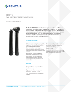


© Copyright 2026