Document 35805
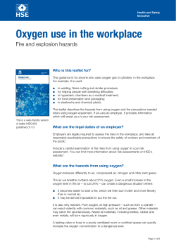
HSE information sheet Safe systems of work for cleaning flexographic, rotary letterpress and gravure printing presses Printing Information Sheet No 3 Introduction This information sheet has been produced by the Printing Industry Advisory Committee (PIAC) in response to concerns about the large number of accidents that continue to occur during the operation and maintenance of printing presses. It deals primarily with safety issues, as other PIAC publications cover health risks. It provides guidance for employers and supervisors on suitable defined safe systems of work appropriate for various cleaning and maintenance tasks on printing presses used in the flexographic and gravure processes, including roll label presses. Employees will also find it useful. The safe systems of work described have been established following risk assessment which takes into consideration the nature of the cleaning task, the safeguarding arrangements and the machine controls provided. Remember that the Management of Health and Safety at Work Regulations 1999 require you to carry out a risk assessment and implement any necessary control measures, including safeguarding and safe systems of work. Regulations 5 and 6 of the Provision and Use of Work Equipment Regulations 1998 (PUWER 98) require that safeguards are maintained. There is a safeguard checklist on the back page which will help to ensure you comply with this requirement. flexographic, gravure and rotary letterpress machines, at what speed they were running and the parts of the press involved. Table 2 Investigated accidents at flexographic, gravure and rotary letterpress machines Duct/anilox/ doctor blade Stereo/impression cylinder Total Production speed 3 16 19 Crawl/inch speed 2 3 5 More detailed analysis has shown that most of the accidents are caused by: ● inadequate safeguards allowing access to inrunning nips; ● guard failure due to lack of maintenance, or guards being removed; ● control deterioration (eg inch travel/crawl speed increasing) due to lack of maintenance; ● unsafe systems of work for cleaning the press. Examples of incidents involving flexographic, rotary letterpress and gravure presses Accident history Table 1 Accidents involving work at all types of printing presses reported to HSE under RIDDOR 1991/92-1995/96 Year 1991/92 1992/93 1993/94 1994/95 1995/96 All 133 99 89 97 87 Major 17 12 13 19 12 As a result of significant under-reporting, these figures only represent a fraction of accidents involving printers. Employers are reminded that the reporting of accidents is a requirement of the Reporting of Injuries, Diseases and Dangerous Occurrences Regulations (RIDDOR) 1995. You can be prosecuted if you fail to do this. Causes of accidents Approximately 70 accidents which occurred during cleaning tasks at printing presses were investigated by Health and Safety Executive (HSE) inspectors from 1986-1996. Table 2 shows the number of accidents at A press operator suffered amputation of his left-hand index finger when it was taken into an in-running nip between the stencil roller and impression roller on a label printing machine varnishing unit. Varnish had spilt onto the machine bed and a rag was used to remove it while the machine ran at production speed. The guard around the varnishing unit was not interlocked. A printer severed his finger tip at the print unit of a Mark Andy 4120 flexographic label press. He opened a sliding interlocked guard to clean the stereo during print run. The machine had a run-down time of approximately 5 seconds. The cleaning cloth, which was wrapped around his index finger, was taken into the nip between the anilox and stereo cylinders. An operator attempted to use a rag to clean the stereo cylinder of a 1985 Manzoni flexographic press following a spillage from the ink duct during the production run. His fingers were trapped between the unguarded stereo and impression cylinders. An interlocked guard was subsequently fitted. A printer received lacerations to his fingers while operating a 1960 Halley, two-colour, web-fed gravure press when attempting to wipe the doctor blade. A blade mark had formed on the printed image and the operator attempted to clean the blade with his fingers while the press was running at production speed. His fingers were taken into the gravure/impression cylinder nip which was unguarded. Unexpected start-up ● Gravure - long-run presses In-running nips between gravure and impression cylinders ● Nip bars adjusted to within 6 mm of the gravure/impression and impression/back impression (boule) cylinders which are designed to allow adjustment for the full range of gravure cylinder diameters. ● Continuous slow crawl should be supplemented by an emergency stop (or ‘stop lock’) control at each print unit. ● If wiping of the doctor blade is required during the print run, provision for safe access should be made. The safe system of work should consider other aspects including lighting and provision of a purpose-designed tool. ● Pre-start audible warning device. What you need to do: A step-by-step approach PIAC recommend that you use the following step-by-step approach to help you to decide on the appropriate system of work for your presses. Remember to consult employees and safety representatives at all stages of the process - they have valuable insights into the daily operation of systems and machinery. Step 1: Assessing safeguarding standards for print units Compare the safeguarding standards (ie the combination of cylinder stopping performance, nip bar position and maximum crawl speed) on your own machines against those in Table 3 and decide whether you need to upgrade what you now have to meet current standards. These standards are commonly accepted and practicable and PIAC believes all printers can achieve them. Standards will differ slightly for make, model, type and age of the press so that the same system of work for a cleaning operation may not be appropriate for what may appear to be similar presses. The control definitions in Table 3 are in italics and they are explained following the table. Table 3 Safeguarding standards Hazard Safeguard Flexographic and rotary letterpress - small to medium size up to 1 m web In-running nips between inking rollers (rotary letterpress), duct, anilox, stereo and impression cylinders ● Removable interlocked guards allowing limited inch and hold-to-run slow crawl only when removed or opened; and ● a fixed nip bar adjusted to within 6 mm of the anilox/duct rollers where these have a separate auxiliary drive which is not stopped by opening of the interlocked guard. Unexpected start-up ● Pre-start audible warning device. Flexographic - larger format, eg flexible packaging In-running nips between duct, anilox, stereo and impression cylinders ● ● Gate/barrier interlocked guards allowing limited inch and hold-to-run slow crawl only when removed or opened; and a fixed nip bar adjusted to within 6 mm of the anilox/duct rollers where these have an auxiliary drive Pre-start audible warning device. Unexpected start-up Gravure - short-run presses In-running nips between gravure and impression cylinders Unexpected start-up, multi- person cleaning ● Interlocking guards fitted either at each print unit or along the length of the press which allow limited inch and holdto-run slow crawl only when open. ● If wiping of the doctor blade is required during the print run, provision for safe access should be made by means of a slot in the interlocked guard. The safe system of work should consider other aspects including lighting and provision of a purpose-designed tool. ● Pre-start audible warning device. Control definitions True inch - a single depression of the control button causing a cylinder movement of 25 mm. It should not be possible to cause uninterrupted movement of the cylinders by repeated depression of the button. Limited inch - a single depression of the control button causing a cylinder movement greater than 25 mm but less than 75 mm. It should not be possible to cause uninterrupted movement of the cylinders by repeated depression of the button. To test inch movement - mark the cylinder and machine frame, inch and measure. Hold-to-run slow crawl - uninterrupted movement of the cylinders at speeds not exceeding 5 m per minute caused by continued depression of the control button. Crawl speed may be increased to a maximum of 10 m per minute only if there is no substantial increase in hazard. Continuous slow crawl - uninterrupted movement of the cylinders at speeds not exceeding 5 m per minute which does not require continued depression of the control button. Crawl speed may be increased to a maximum of 10 m per minute only if there is no substantial increase in hazard. To measure crawl speed - count the number of revolutions per minute and multiply by the cylinder circumference. Step 2: Decide on the appropriate safe system for cleaning This is determined by the standard of safeguards and the machine controls. Apply the following hierarchy: ● Reduce the frequency of cleaning to that necessary to maintain the quality of work, so reducing the need to approach hazardous parts. ● Use automatic wash-up systems. Where provided, make full use of automatic inking roller wash-up systems. ● Perform cleaning work off-press so that approach to cylinders under powered movement is reduced. Rotary letterpress stencils or formes, the print units of modern rotary label presses, flexographic stereos and gravure cylinders are often cleaned off the press, depending on the length of the print run. ● Select a safe system of work which ensures that operators do not need to place their hands near accessible in-running nips. Appropriate methods of work for press cleaning are listed in Table 4. Where manual on-press cleaning is necessary, in each case make sure that: ● cleaning solvent is applied with a suitable cloth folded to form a pad without loose edges using close-fitting impervious gloves; ● cleaning solvent is kept within a suitable sealed container to prevent spillage and evaporation; ● used cleaning cloths are put in a closed, fireresisting container; ● adequate ventilation is provided. applying the solvent-soaked cloth. In multi-person operation, each person must retain control over the re-setting of their own emergency stop or ‘safe’ button so that it is not possible for another person to cause the press to move unexpectedly. Inch-stop-clean/hold-to-run-stop-clean. In this system the cylinders are rotated enough to expose the next section of cylinder surface to be cleaned. The hand with the cleaning cloth is held clear of the cylinder while it is rotating. The cylinder should be stationary before the solvent-soaked cloth is applied. For machines with a true or limited inch control, several depressions of the button may be required to expose enough of the cylinder surface to clean. Multi-person cleaning is acceptable using this system only where zoned print unit controls are provided, ie cylinder movement at each unit can occur and be controlled independently of the rest. Slow crawl cleaning. In this method, the cleaning cloth is applied to the cylinder as it rotates at very slow speed. Movement is controlled using hold-to-run slow crawl controls or non-hold-to-run controls (continuous slow crawl). Table 4 Appropriate systems of work for press cleaning Task Risk factors System of work Flexographic/rotary letterpress Cleaning Absence of nip bars duct/anilox rollers, single-person ● Inch-stop-clean. Cleaning duct/anilox rollers, multi-person Absence of nip bars ● Inch-stop-lockclean. If press has zoned controls allowing independent movement of print unit cylinders, inchstop-clean. Cleaning stereo mid-run, singleperson Accessibility to inrunning nip when interlocked guard raised ● Inch-stop-clean. Cleaning stereo mid-run, multiperson Accessibility to inrunning nip when interlocked guard raised ● Inch-stop-lockclean. If press has zoned controls allowing independent movement of print unit cylinders, inchstop-clean. Cleaning stereo at end of run Stereo removed from press ● ● ● Defined safe systems of work for press cleaning There are three main safe systems: Inch-stop-lock-clean/hold-to-run-stop-lock-clean. In this system, the press is subject to limited movement using the inch/hold-to-run button, stopped and the power isolated using the ‘safe’ or emergency stop button before Off-machine manual or autowashing. Gravure Wiping doctor blades Cleaning gravure/impression cylinders mid-run, single-person Cleaning gravure/impression cylinders mid-run, multi-person Approach close to in-running nips at production speed Accessibility to inrunning nips when interlocked guard raised Accessibility to in running nips when interlocked guard raised Cleaning Gravure cylinder gravure/impression removed from press cylinders at end of run ● ● ● ● ● ● Use of purposemade tool and properly adjusted nip bar or slot in interlocked guard. Inch-stop-clean. Forward slow crawl cleaning only if nip bars and emergency stops are provided and a guard checklist completed. Inch-stop-lockclean. Forward slow crawl cleaning only if nip bars and emergency stops are provided and a guard checklist completed. Off machine manual or autowashing. Step 3: Train and instruct employees As an employer you need to train and instruct employees in the appropriate system of work and safeguard checks for their press. Systems of work and guard checklists need to be documented. Make sure that you discuss the options with employees and safety representatives and agree safe systems of work with them. You should ensure that the press controls are understood and that the reason a particular system of work is needed is properly explained. Make it clear that employees will be accountable for this work. You also need to explain what they should do if a safeguarding or control defect is found and you should support any employee who identifies a hazardous defect. Any such defects should be investigated and dealt with before continuing to use the machine. It is a good idea to attach a copy of a safeguard checklist to each press. This will act as a reminder and will show that the minder has an important role to play. Safeguard checklist ● interlocks have not been intentionally defeated; ● adjustable nip bars are within 6 mm of the cylinder surface; ● inch and limited inch movement have not increased; ● crawl speed is limited to 5 m per minute; ● pre-start warning devices are audible. Step 4: Monitoring and review by managers Completion of the press operator’s daily and weekly checks will help ensure compliance with regulation 5 of PUWER 98, and managers need to check periodically that these agreed procedures are being implemented. Satisfy yourself for example that: ● safeguard checklists have been completed and signed, and any defects noted and reported; ● the correct system of work is being used. Where your risk assessment has exceptionally shown that slow crawl cleaning is appropriate for gravure presses, to ensure compliance with regulation 6 of PUWER 98, the condition and position of the nip bar in particular should be checked at regular intervals. This is because an increase in the distance of the nip bar from the cylinder surface would lead to a significant risk to the operator during cleaning on slow crawl. The results of the check should be recorded and kept until the time of the next inspection. If you routinely find problems following any check, investigate to find the root cause, and then reassess. By doing this you will also be able to determine the most appropriate frequency for inspection. Further information HSE priced and free publications are available by mail order from HSE Books, PO Box 1999, Sudbury, Suffolk CO10 2WA. Tel: 01787 881165 Fax: 01787 313995. Website: www.hsebooks.co.uk HSE priced publications are also available from good booksellers. For other enquiries ring HSE’s InfoLine Tel: 08701 545500, or write to HSE’s Information Centre, Broad Lane, Sheffield S3 7HQ. Website: www.hse.gov.uk This leaflet was prepared by the Printing Industry Advisory Committee and has been agreed by the Health and Safety Commission. It contains notes on good practice which are not compulsory but which you may find helpful in considering what you need to do. Check that: ● cams on interlocking guards have not moved out of adjustment; Printed and published by the Health and Safety Executive This publication may be freely reproduced, except for advertising, endorsement or commercial purposes. The information is current at 7/00. Please acknowledge the source as HSE. 7/00 PIS3 C100
© Copyright 2026
